4 layers84 × 28.8 mm

 TobleMiner/oled-nametag54
A ESP32-based OLED nametag
Oled nametag is an open-source printed circuit board by TobleMiner, from the TobleMiner/oled-nametag repository on GitHub, published under the CERN-OHL-P-2.0 licence. It is a 4-layer board of 88 × 30 mm with 123 parts on 104 nets, routed with 2,086 tracks and 297 vias.
It is built around the ESP32-S3, TPS61040DBV and TPS63001DRC, with the DW01+G, SRV05-4 and 1N5819WS among its other parts. Its parts include 41 capacitors, 33 resistors, 13 ICs, 5 diodes and 4 transistors. It belongs with the lEDs and displays boards and the ESP32 boards of this library.


This repository contains the design file for a fully open source electronic name badge with monochrome OLED display.
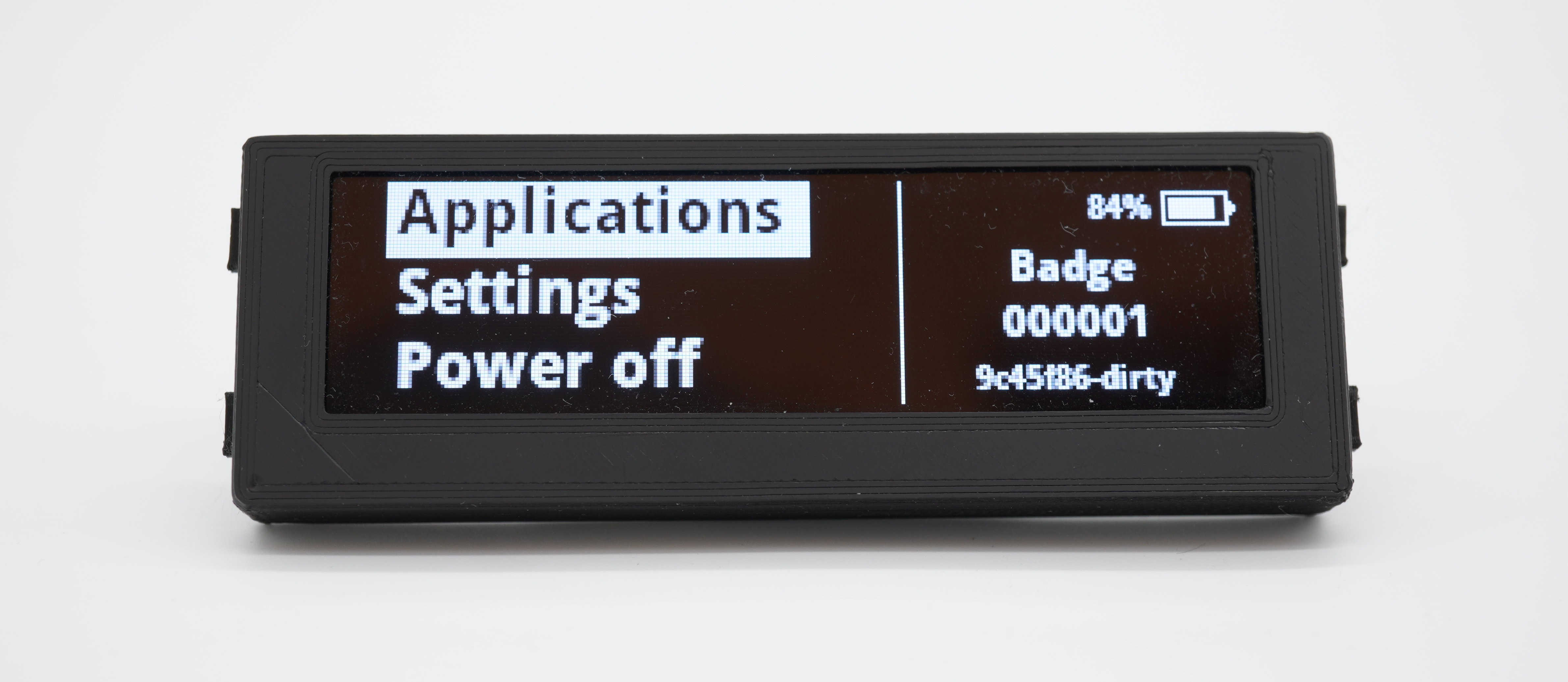
I would not recommend ordering RevA yet as there are a number of issues with that version. See Rev A issues for details.
All fabrication files are located in fab.
The main PCB have been optimized for manufacturing through JLCPCB.
Most components can also be assmbled by JLCPCB directly.
The display used can be one of:
Other menchanically compatible SSD1322-based parts can also be used.
The device housing is 3D printable and designed to suit most 3D printing processes, especially SLA and FDM. Good results have also been achieved with MJF and SLS printing.
There are three different fabrication files for the case top part, depending on the thickness of the lithium batteries used.
Additionally 4 button actuators need to be printed for each OLED badge. Those are also contained in the OpenSCAD design files and fabrication output.
When choosing PCB assembly through JLCPCB only two PCB components need to be assmbled manually:
The display is mounted to the top side of the PCB using double sided adhesive tape with a thickness of .15mm. Align to top of the PCB (side with USB-C port) with the top of the display.
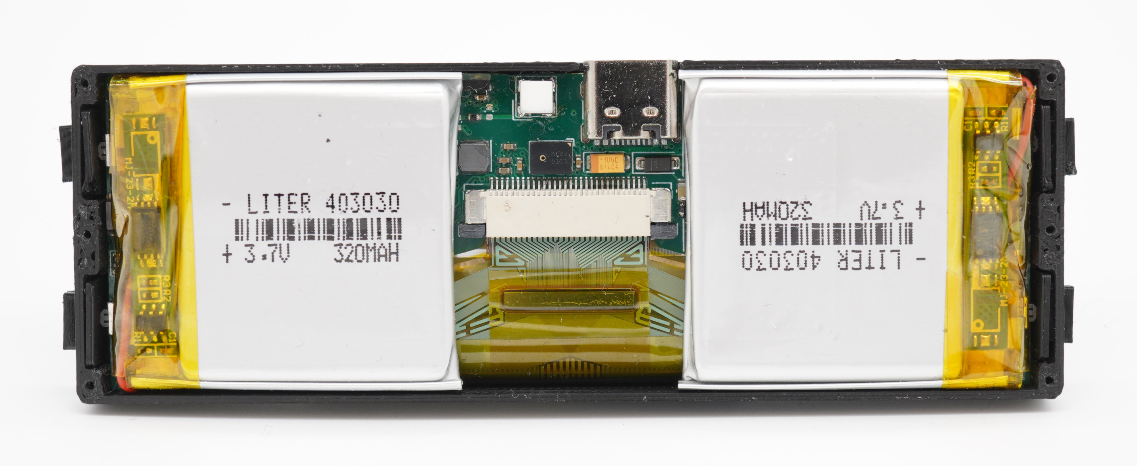
The device needs two 303030, 403030 or 503030 cells as a power source.
The batteries need to be mounted on the bottom side of the PCB. Double-
sided adhesive foam tape with a thickness of 2mm is recommended for this
purpose.
Place the button actuators into the housing first, then slide in the PCB with both display and batteries attached and stuck down.
At this point the badge should look like this:
Finally screw on the top lid iwht six 4mm M1 fine thread self tapping screws.
The OLED badge is running fully Open Source firmware. For the purpose of
enabling WLAN connectivity vendor-provided binary blobs are required.
The firmware source can be found here:
https://github.com/TobleMiner/oled-nametag-firmware
Rev A is very much a prototype. It has the following known issues:
The current state of the repository does not reflect Rev A but a potential Rev B. Please note that this state of the design has not been tested yet.
| Qty | Value | Footprint | References |
|---|---|---|---|
| 16 | 100nF | Capacitor_SMD:C_0402_1005Metric | C2, C9, C14, C16, C17, C21, C22, C25, C27, C34, C35, C36, C37, C38, C39, C41 |
| 9 | 10uF | Capacitor_SMD:C_0402_1005Metric | C4, C5, C13, C18, C26, C28, C30, C31, C32 |
| 8 | 5.1k | Resistor_SMD:R_0402_1005Metric | R5, R8, R9, R16, R19, R20, R28, R31 |
| 7 | 100R | Resistor_SMD:R_0402_1005Metric | R1, R22, R23, R24, R25, R27, R32 |
| 7 | 1uF | Capacitor_SMD:C_0402_1005Metric | C1, C7, C10, C15, C23, C29, C40 |
| 5 | 10k | Resistor_SMD:R_0402_1005Metric | R15, R17, R29, R30, R33 |
| 4 | 47k | Resistor_SMD:R_0402_1005Metric | R4, R6, R10, R11 |
| 3 | 10uF 25V | Capacitor_SMD:C_0603_1608Metric | C3, C6, C8 |
| 2 | 10pF | Capacitor_SMD:C_0402_1005Metric | C11, C12 |
| 2 | 1N5819WS | Diode_SMD:D_SOD-323 | D1, D2 |
| 2 | 1k | Resistor_SMD:R_0402_1005Metric | R12, R21 |
| 2 | 2A | Resistor_SMD:R_0603_1608Metric | F2, F3 |
| 2 | AO3401A | Package_TO_SOT_SMD:SOT-23 | Q1, Q2 |
| 2 | BAT+ | TestPoint:TestPoint_Pad_2.0x2.0mm | TP2, TP4 |
| 2 | BAT- | TestPoint:TestPoint_Pad_2.0x2.0mm | TP3, TP5 |
| 2 | DNP | Capacitor_SMD:C_0402_1005Metric | C19, C20 |
| 2 | ToolingHole | ToolingHole:ToolingHole_JLCSMT | H1, H2 |
| 2 | ~ | Sensor_Vishay:VEML3235SL | U4, U13 |
| 1 | +12v5 | TestPoint:TestPoint_Pad_1.0x1.0mm | TP7 |
| 1 | +3v3 | TestPoint:TestPoint_Pad_1.0x1.0mm | TP8 |
| 1 | 0R | Resistor_SMD:R_0402_1005Metric | R7 |
| 1 | 0R | Inductor_SMD:L_0402_1005Metric | L2 |
| 1 | 10mR | Resistor_SMD:R_0805_2012Metric | R26 |
| 1 | 10uF | Capacitor_Tantalum_SMD:CP_EIA-3216-10_Kemet-I | C33 |
| 1 | 10uH | Inductor_SMD:L_1210_3225Metric | L1 |
| 1 | 1N4148WS | Diode_SMD:D_SOD-323 | D5 |
| 1 | 1nF | Capacitor_SMD:C_1206_3216Metric | C24 |
| 1 | 2.2uH | Inductor_SMD:L_Taiyo-Yuden_MD-3030 | L3 |
| 1 | 2.7k | Resistor_SMD:R_0603_1608Metric | R14 |
| 1 | 200k | Resistor_SMD:R_0805_2012Metric | R18 |
| 1 | 2N7002 | Package_TO_SOT_SMD:SOT-23 | Q6 |
| 1 | 40MHz | Crystal:Crystal_SMD_2016-4Pin_2.0x1.6mm | Y1 |
| 1 | 470R | Resistor_SMD:R_0402_1005Metric | R13 |
| 1 | 50R | Resistor_SMD:R_0402_1005Metric | R3 |
| 1 | 680k | Resistor_SMD:R_0603_1608Metric | R2 |
| 1 | Antenna_Shield | Antenna_SMD_Molex:2065130001 | AE1 |
| 1 | B5819W | Diode_SMD:D_SOD-123 | D3 |
| 1 | BAV70 | Package_TO_SOT_SMD:SOT-23 | D4 |
| 1 | BQ24081 | Package_Texas:Texas_DRC0010J_ThermalVias.3 | U8 |
| 1 | BQ27546 | Package_DSBGA:DSBGA-15_BQ27546_I2C_1.95x2.6mm_P0.5mm | U10 |
| 1 | BTN1 | Button_Switch_SMD:SW_SPST_B3U-3000P-B | SW2 |
| 1 | BTN2 | Button_Switch_SMD:SW_SPST_B3U-3000P-B | SW3 |
| 1 | BTN3 | Button_Switch_SMD:SW_SPST_B3U-3000P-B | SW4 |
| 1 | Bead | Inductor_SMD:L_0805_2012Metric | FB1 |
| 1 | DW01+G | Package_TO_SOT_SMD:SOT-23-6 | U7 |
| 1 | ESP-PSRAM32 | Package_SO:SOIC-8_3.9x4.9mm_P1.27mm | U12 |
| 1 | ESP32-S3 | Package_QFN_ESP32:QFN-56-1EP_7x7mm_P0.4mm_EP4x4mm_ThermalVias_0.3mm | U3 |
| 1 | FS8205A | Package_TO_SOT_SMD:SOT-23-6 | Q3 |
| 1 | GND | TestPoint:TestPoint_Pad_1.0x1.0mm | TP9 |
| 1 | I2C | Connector_PinHeader_2.54mm:PinHeader_1x03_P2.54mm_Vertical | J2 |
| 1 | ICAL+ | TestPoint:TestPoint_Pad_1.0x1.0mm | TP6 |
| 1 | ICAL- | TestPoint:TestPoint_Pad_1.0x1.0mm | TP1 |
| 1 | LOAD | Connector_PinHeader_2.54mm:PinHeader_1x02_P2.54mm_Vertical | J3 |
| 1 | Power | Button_Switch_SMD:SW_SPST_B3U-3000P-B | SW1 |
| 1 | SRV05-4 | Package_TO_SOT_SMD:SOT-23-6 | U9 |
| 1 | TPS61040DBV | Package_TO_SOT_SMD:SOT-23-5 | U6 |
| 1 | TPS63001 | Package_Texas:Texas_DRC0010J_ThermalVias.3 | U11 |
| 1 | USB_C_Receptacle_USB2.0 | Connector_USB:USB_C_Receptacle_Palconn_UTC16-G | J1 |
| 1 | VCAL | TestPoint:TestPoint_Pad_1.0x1.0mm | TP10 |
| 1 | W25Q128 | Package_SON:WSON-8-1EP_6x5mm_P1.27mm_EP3.4x4.3mm | U2 |
| 1 | ~ | FFC_HDGC:FFC_30P_TC_P0.5mm_0.5K-AS-30PWB | U1 |
| 1 | ~ | Package_LGA_ST:ST_HCLGA-4LD_3x4mm | U5 |

rusefi/hw_microRusEfi
microRusEfi board for rusEfi ECU

rjsc/BECom
BECom - Battery Emulator Companion - Open Source Hardware, designed to run dalathegreat/Battery-Emulator


STB1019/BLINDO2.0
Blindo is an open source project made by the members of IEEE Student Branch 1019 from Brescia University (Università degli Studi di Brescia) in collaboration with the organization (Informatici Senza…

plinkysynth/plinky_public
a public release of the plinky sw and hw

TobleMiner/DC-UPS
A small DC UPS, designed to keep small appliances like consumer network equipment running during power outages

Acmex2564/Z31-DigiDash
Reverse Engineering of the 300zx (Z31) Digital Cluster & Design of replacement PCBs
It measures 88 × 30 mm and has 4 copper layers, 1 mm thick.
123 parts, built around the ESP32-S3, TPS61040DBV, TPS63001DRC and DW01+G. The full list of its parts is on this page, with links to each part's symbol and footprint where PCBKit's library has them.
From the TobleMiner/oled-nametag repository on GitHub, at the commit this page was made from: the board is oled-nametag.kicad_pcb and its schematic esp32.kicad_sch. PCBKit opens the board in the browser, with nothing to install.
Its repository publishes it under the CERN-OHL-P-2.0 licence: you may reuse it on that licence's terms (keep the author's notice, and for a copyleft licence share your changes alike).