6 layers84 × 50 mm
Solar ribbit
Ribbit-Network/ribbit-network-frog-hardware
The sensor for the world's largest crowdsourced network of open-source, low-cost, GHG Gas Detection Sensors.
171 parts107MIT

 Project-Emerge/rover-circuit
The Rover Circuit is a comprehensive controller board designed for robotics applications, specifically targeted at robot rovers.
Rover circuit is an open-source printed circuit board by Project-Emerge, from the Project-Emerge/rover-circuit repository on GitHub, published under the MIT licence. It is a 4-layer board of 72.8 × 75 mm with 108 parts on 136 nets, routed with 640 tracks and 499 vias.
It is built around the ESP32-C6-WROOM-1-N8, DWM1000 and AP63200WU, with the AP63205WU, DRV8833PWPR and MMC5983MA among its other parts. Its parts include 35 capacitors, 21 resistors, 11 ICs, 8 connectors and 5 diodes. It belongs with the robots and motor control boards and the ESP32 and RISC-V boards of this library.


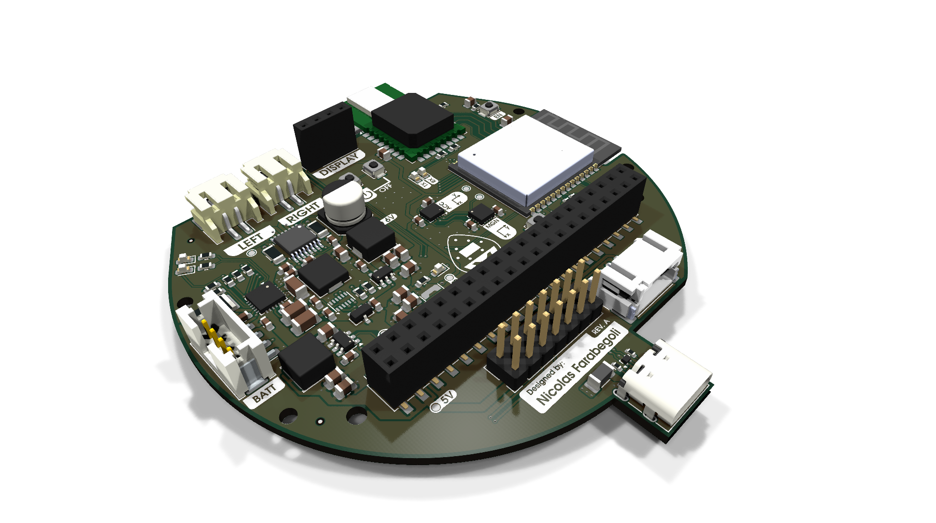
The Rover Circuit is a comprehensive controller board designed for robotics applications, specifically targeted at robot rovers. A key goal of this project is to make swarm robotics accessible to students, educators, and researchers, providing an affordable and easy-to-use platform for experimenting with multi-agent systems and decentralized control.
It integrates dual-motor driving capabilities, 2-cell Li-ion battery management with USB-C charging, and provides multiple power domains (3.3V, 5V, 6V) for logic, sensors, and external compute modules like a Raspberry Pi. The board includes I2C and GPIO interfaces to facilitate communication with various sensors and control systems, making it a compact, all-in-one hardware platform for mobile robot development.
These components work together to provide a complete, robust sensing, processing, and locomotion backend, allowing developers to focus on high-level swarm robotics software and decentralized algorithms without worrying about hardware integration.


MIT License - see LICENSE file for details.
| Qty | Value | Footprint | References |
|---|---|---|---|
| 6 | 22uF | Capacitor_SMD:C_0805_2012Metric | C17, C20, C21, C23, C24, C28 |
| 5 | 1uF | Capacitor_SMD:C_0603_1608Metric | C2, C16, C31, C32, C35 |
| 4 | 100nF | Capacitor_SMD:C_0603_1608Metric | C13, C19, C29, C30 |
| 4 | 10k | Resistor_SMD:R_0603_1608Metric | R3, R12, R18, R21 |
| 4 | 10uF | Capacitor_SMD:C_0805_2012Metric | C11, C18, C22, C25 |
| 4 | MountingHole | MountingHole:MountingHole_2.2mm_M2 | H1, H2, H3, H4 |
| 3 | 0.1uF | Capacitor_SMD:C_0805_2012Metric | C1, C27, C33 |
| 3 | Fiducial | Fiducial:Fiducial_0.5mm_Mask1mm | FID4, FID5, FID6 |
| 2 | 10uF | Capacitor_SMD:C_0603_1608Metric | C14, C15 |
| 2 | 2.2k | Resistor_SMD:R_0603_1608Metric | R1, R8 |
| 2 | 2.2uF | Capacitor_SMD:C_0603_1608Metric | C8, C26 |
| 2 | 200m | Resistor_SMD:R_1206_3216Metric | R9, R10 |
| 2 | 22uF | Capacitor_SMD:C_1206_3216Metric | C3, C12 |
| 2 | 4.7k | Resistor_SMD:R_0603_1608Metric | R16, R17 |
| 2 | 470 | Resistor_SMD:R_0603_1608Metric | R19, R20 |
| 2 | 5.1K | Resistor_SMD:R_0402_1005Metric | R13, R14 |
| 2 | BLUE | LED_SMD:LED_0603_1608Metric | D5, D6 |
| 2 | Raspberry | MountingHole:MountingHole_2.5mm | H7, H8 |
| 1 | 1.1K | Resistor_SMD:R_0603_1608Metric | R2 |
| 1 | 10 | Resistor_SMD:R_2512_6332Metric | R5 |
| 1 | 100K | Resistor_SMD:R_0603_1608Metric | R15 |
| 1 | 100uF | Capacitor_SMD:CP_Elec_6.3x5.4 | C10 |
| 1 | 10nF | Capacitor_SMD:C_0603_1608Metric | C9 |
| 1 | 10uF | Capacitor_SMD:C_1206_3216Metric | C5 |
| 1 | 10uH | Inductor_SMD:L_Sunlord_MWSA0503S | L4 |
| 1 | 1uH | Inductor_SMD:L_Sunlord_MWSA0518S | L1 |
| 1 | 2.2uH | Inductor_SMD:L_Coilcraft_LPS3010 | L2 |
| 1 | 22uF | Capacitor_SMD:C_0603_1608Metric | C7 |
| 1 | 30.1k | Resistor_SMD:R_0603_1608Metric | R7 |
| 1 | 300 | Resistor_SMD:R_0603_1608Metric | R4 |
| 1 | 3V3 TP | TestPoint:TestPoint_Pad_D1.0mm | TP1 |
| 1 | 4.7uF | Capacitor_SMD:C_0603_1608Metric | C6 |
| 1 | 4.7uH | Inductor_SMD:L_Chilisin_BWVS00505030 | L3 |
| 1 | 470nF | Capacitor_SMD:C_0603_1608Metric | C34 |
| 1 | 47nF | Capacitor_SMD:C_0603_1608Metric | C4 |
| 1 | 5.23k | Resistor_SMD:R_0603_1608Metric | R6 |
| 1 | 5V TP | TestPoint:TestPoint_Pad_D1.0mm | TP2 |
| 1 | 64.9k | Resistor_SMD:R_0603_1608Metric | R11 |
| 1 | 6V TP | TestPoint:TestPoint_Pad_D1.0mm | TP3 |
| 1 | AP63200WU | Package_TO_SOT_SMD:TSOT-23-6 | U5 |
| 1 | AP63205WU | Package_TO_SOT_SMD:TSOT-23-6 | U7 |
| 1 | BMI270 | Package_LGA:Bosch_LGA-14_3x2.5mm_P0.5mm | U11 |
| 1 | BQ25887RGE | Package_DFN_QFN:Texas_RGE0024H_VQFN-24-1EP_4x4mm_P0.5mm_EP2.7x2.7mm | U2 |
| 1 | Batt | TestPoint:TestPoint_Pad_D1.0mm | TP6 |
| 1 | Battery Connector | Connector_JST:JST_PH_B4B-PH-SM4-TB_1x04-1MP_P2.00mm_Vertical | J9 |
| 1 | DRV8833PWP | Package_SO:HTSSOP-16-1EP_4.4x5mm_P0.65mm_EP3.4x5mm_Mask2.46x2.31mm_ThermalVias | U3 |
| 1 | DWM1000 | RF_Module:DWM1000 | DWM1 |
| 1 | ESP32-C6-WROOM-1-N8 | lib_fp:XCVR_ESP32-C6-WROOM-1-N8 | U6 |
| 1 | Expansion Header | Connector_PinHeader_2.54mm:PinHeader_2x07_P2.54mm_Vertical | J6 |
| 1 | GRN | LED_SMD:LED_0603_1608Metric | D2 |
| 1 | GZ3216D101TF | Inductor_SMD:L_1206_3216Metric | FB1 |
| 1 | INT1 | TestPoint:TestPoint_Pad_D1.0mm | TP10 |
| 1 | LED | LED_SMD:LED_0603_1608Metric | D3 |
| 1 | Left Motor | Connector_JST:JST_PH_S2B-PH-SM4-TB_1x02-1MP_P2.00mm_Horizontal | J8 |
| 1 | MCP1799T-5002H/TT | Package_TO_SOT_SMD:SOT-23 | U12 |
| 1 | MMC5983MA | Package_LGA:LGA-16_3x3mm_P0.5mm | U1 |
| 1 | MMC5983_INT | TestPoint:TestPoint_Pad_D1.0mm | TP9 |
| 1 | OLED Display | Connector_PinSocket_2.54mm:PinSocket_1x04_P2.54mm_Vertical | J3 |
| 1 | Proximity | Connector_JST:JST_PH_S4B-PH-SM4-TB_1x04-1MP_P2.00mm_Horizontal | J4 |
| 1 | RED | LED_SMD:LED_0603_1608Metric | D1 |
| 1 | Raspberry Pi Hat Connector | Connector_PinSocket_2.54mm:PinSocket_2x20_P2.54mm_Vertical_SMD | J5 |
| 1 | Right Motor | Connector_JST:JST_PH_S2B-PH-SM4-TB_1x02-1MP_P2.00mm_Horizontal | J7 |
| 1 | SCL | TestPoint:TestPoint_Pad_D1.0mm | TP5 |
| 1 | SDA | TestPoint:TestPoint_Pad_D1.0mm | TP4 |
| 1 | STM6601CM2DDM6F | Package_DFN_QFN:TDFN-12_2x3mm_P0.5mm | U8 |
| 1 | SW_EN | Button_Switch_SMD:SW_SPST_B3U-1000P | SW1 |
| 1 | SW_IO0 | Button_Switch_SMD:SW_SPST_B3U-1000P | SW2 |
| 1 | TPD2EUSB30 | Package_TO_SOT_SMD:Texas_DRT-3 | U4 |
| 1 | TPS62162DSG | Package_SON:WSON-8-1EP_2x2mm_P0.5mm_EP0.9x1.6mm_ThermalVias | U9 |
| 1 | USB C Connector | Connector_USB:USB_C_Receptacle_G-Switch_GT-USB-7010ASV | J2 |
| 1 | ~{FAULT} | TestPoint:TestPoint_Pad_D1.0mm | TP7 |
| 1 | ~{PB} | Button_Switch_SMD:SW_SPST_B3U-1000P | SW4 |
| 1 | ~{SR} | Button_Switch_SMD:SW_SPST_B3U-1000P | SW3 |
Ribbit-Network/ribbit-network-frog-hardware
The sensor for the world's largest crowdsourced network of open-source, low-cost, GHG Gas Detection Sensors.

mjbots/power_dist
This repository contains hardware and firmware for the mjbots powerdist and mjpower-ss boards. Both provide pre-charge, over-current limiting and connector fanout.

pez-globo/pufferfish-electronics
Circuit schematics and PCB layouts for the Pufferfish ventilator.

Tinkerbug-Robotics/TinkerRocket
Model rocket flight computer, ground station, iOS app, and simulation


HeyPCB/quack-core
Brain board for the Open Duck Mini: Pi Zero 2W carrier, 14-servo STS bus, fused 2S power path in stitched copper zones (15-18 A battery side), USB-C charging with balancing, IMU.

Mmessiter/LDRC_V2
LockDown Radio Control V2 — RXV2 receiver and Rotorflight/simulator dongle, the iOS and Android apps, and the TXV2 transmitter. Free and open source.

k6V457/maturitni_prace
GOALS: - [x] Create this repository - [ ] Create graduation thesis - [ ] Create template in $\LaTeX$ - [ ] fill in blank spaces - [ ] modify template for SPSKA purposes - [ ] Write INTRO and theoretical part - [ ] start…
It measures 72.8 × 75 mm and has 4 copper layers, 1.6 mm thick.
108 parts, built around the ESP32-C6-WROOM-1-N8, DWM1000, AP63200WU and AP63205WU. The full list of its parts is on this page, with links to each part's symbol and footprint where PCBKit's library has them.
From the Project-Emerge/rover-circuit repository on GitHub, at the commit this page was made from: the board is rover-circuit.kicad_pcb and its schematic display.kicad_sch. PCBKit opens the board in the browser, with nothing to install.
Its repository publishes it under the MIT licence: you may reuse it on that licence's terms (keep the author's notice, and for a copyleft licence share your changes alike).