4 layers83.3 × 91.7 mm
TXV2 MAIN
Mmessiter/LDRC_V2
LockDown Radio Control V2 — RXV2 receiver and Rotorflight/simulator dongle, the iOS and Android apps, and the TXV2 transmitter. Free and open source.
61 parts1GPL-3.0

 Mmessiter/LDRC_V21
LockDown Radio Control V2 — RXV2 receiver and Rotorflight/simulator dongle, the iOS and Android apps, and the TXV2 transmitter. Free and open source.
TXV2 MAIN revB is an open-source printed circuit board by Mmessiter, from the Mmessiter/LDRC_V2 repository on GitHub, published under the GPL-3.0 licence. It is a 4-layer board of 83.3 × 91.7 mm with 64 parts on 93 nets, routed with 948 tracks and 70 vias.
It is built around the ESP32-S3-DEVKITC-1-N8, NRF24L01 and AMS1117-3.3, with the BQ25887RGE, SS14 and CR2032 among its other parts. Its parts include 19 connectors, 15 resistors, 12 capacitors, 8 ICs and 4 diodes. It belongs with the radio and wireless boards and the ESP32 boards of this library.


[!WARNING] The board in this folder is wrong. Do not order it, and do not build it. It can destroy a XIAO, and could harm your flight controller.
RXV2_DONGLE_gerbers.zip, RXV2_DONGLE.kicad_pcb, render.png, make_dongle.py.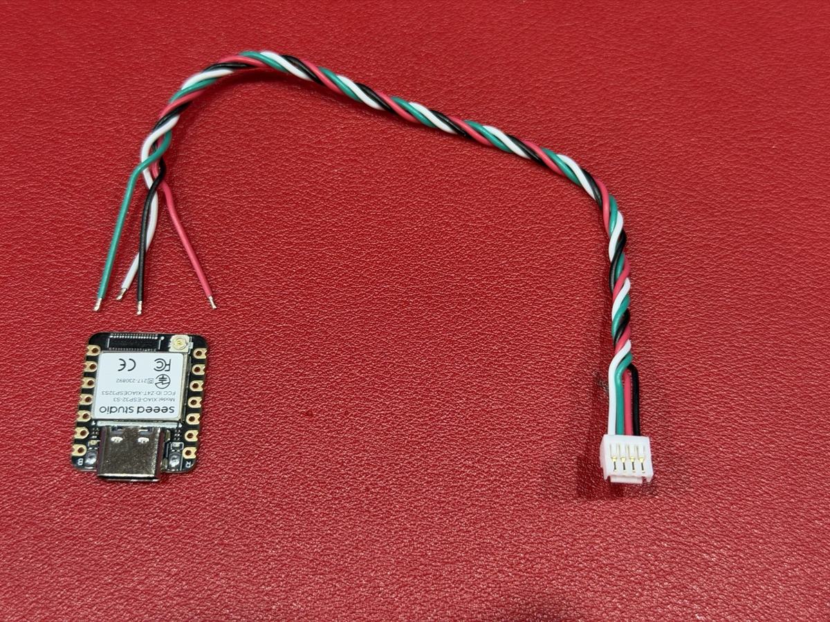
All a dongle needs: a XIAO ESP32-S3 and a four-wire lead (here the one from the Nexus box).
You need:
Wire it:
| Flight controller's port | XIAO pad | Colour on Malcolm's Nexus lead |
|---|---|---|
| RX | D6 | white |
| TX | D5 | green |
| + 5 V | 5V | red |
| − | GND | black |
Plug it in:
Flash it in your browser: messiter.com/rotorflight/flash.html.
The full guide, with photos, other flight controllers and first switch-on: messiter.com/rotorflight/dongle.html.
Licence: boards CERN-OHL-S-2.0. See ../../../LICENSING.md.
| Qty | Value | Footprint | References |
|---|---|---|---|
| 4 | 10uF | Capacitor_SMD:C_1206_3216Metric | C2, C3, C4, C9 |
| 4 | M3 | MountingHole:MountingHole_3.2mm_M3 | H1, H2, H3, H4 |
| 2 | 100nF | Capacitor_SMD:C_0805_2012Metric | C10, C11 |
| 2 | 330R | Resistor_SMD:R_0805_2012Metric | R1, R14 |
| 2 | 4.7k | Resistor_SMD:R_0805_2012Metric | R12, R13 |
| 2 | 470R | Resistor_SMD:R_0805_2012Metric | R9, R10 |
| 2 | 5.1k | Resistor_SMD:R_0805_2012Metric | R7, R8 |
| 2 | 68R | Resistor_SMD:R_1206_3216Metric | R2, R3 |
| 2 | SS14 | Diode_SMD:D_SMA | D3, D4 |
| 1 | 10uF 25V | C_0805_2012Metric | C12 |
| 1 | 15k | Resistor_SMD:R_0805_2012Metric | R16 |
| 1 | 1uF | Capacitor_SMD:C_0805_2012Metric | C1 |
| 1 | 1uH | Inductor_SMD:L_Vishay_IHLP-2020 | L1 |
| 1 | 220uF | Capacitor_SMD:CP_Elec_6.3x7.7 | C8 |
| 1 | 374R | Resistor_SMD:R_0805_2012Metric | R6 |
| 1 | 4.7uF | Capacitor_SMD:C_0805_2012Metric | C7 |
| 1 | 47k | Resistor_SMD:R_0805_2012Metric | R15 |
| 1 | 47nF | Capacitor_SMD:C_0805_2012Metric | C6 |
| 1 | 47pF | Capacitor_SMD:C_0805_2012Metric | C5 |
| 1 | 5.11k | Resistor_SMD:R_0805_2012Metric | R4 |
| 1 | 5V buck MAIN | TXV2:Buck3pin_VGV | U5 |
| 1 | 5V buck NEXT | TXV2:Buck3pin_VGV | U9 |
| 1 | 7.5k | Resistor_SMD:R_0805_2012Metric | R5 |
| 1 | AMS1117-3.3 | Package_TO_SOT_SMD:SOT-223-3_TabPin2 | U8 |
| 1 | BAL | Connector_JST:JST_XH_B2B-XH-A_1x02_P2.50mm_Vertical | J4 |
| 1 | BATT | Connector_AMASS:AMASS_XT30U-F_1x02_P5.0mm_Vertical | J3 |
| 1 | BQ25887 | Package_DFN_QFN:HVQFN-24-1EP_4x4mm_P0.5mm_EP2.6x2.6mm_ThermalVias | U7 |
| 1 | BTN | Connector_JST:JST_XH_B2B-XH-A_1x02_P2.50mm_Vertical | J5 |
| 1 | CHG | LED_SMD:LED_0805_2012Metric | D2 |
| 1 | CR2032 | Battery:Battery_Panasonic_CR2032-VS1N_Vertical_CircularHoles | BT1 |
| 1 | ESP-A | Connector_PinHeader_2.54mm:PinHeader_1x12_P2.54mm_Vertical | J15 |
| 1 | ESP-B | Connector_PinHeader_2.54mm:PinHeader_1x12_P2.54mm_Vertical | J16 |
| 1 | ESP32-S3-DevKitC | TXV2:DevKitC1_Socket | U2 |
| 1 | GIM L H | Connector_JST:JST_PH_B3B-PH-K_1x03_P2.00mm_Vertical | J7B |
| 1 | GIM L V | Connector_JST:JST_PH_B3B-PH-K_1x03_P2.00mm_Vertical | J7 |
| 1 | GIM R H | Connector_JST:JST_PH_B3B-PH-K_1x03_P2.00mm_Vertical | J6B |
| 1 | GIM R V | Connector_JST:JST_PH_B3B-PH-K_1x03_P2.00mm_Vertical | J6 |
| 1 | I2C | Connector_JST:JST_XH_B4B-XH-A_1x04_P2.50mm_Vertical | J13 |
| 1 | KNOBS | Connector_JST:JST_XH_B6B-XH-A_1x06_P2.50mm_Vertical | J8 |
| 1 | NEXTION | Connector_PinHeader_2.54mm:PinHeader_1x05_P2.54mm_Vertical | J2 |
| 1 | PWR | LED_SMD:LED_0805_2012Metric | D1 |
| 1 | Pololu 2808 | TXV2:Pololu2808_PSW03C | U4 |
| 1 | QWIIC | Connector_JST:JST_SH_BM04B-SRSS-TB_1x04-1MP_P1.00mm_Vertical | J12 |
| 1 | RGB LED | Connector_JST:JST_XH_B3B-XH-A_1x03_P2.50mm_Vertical | J11 |
| 1 | RTC | Connector_JST:JST_XH_B2B-XH-A_1x02_P2.50mm_Vertical | J14 |
| 1 | SWITCHES | Connector_JST:JST_XH_B9B-XH-A_1x09_P2.50mm_Vertical | J9 |
| 1 | TRIMS | Connector_JST:JST_XH_B9B-XH-A_1x09_P2.50mm_Vertical | J10 |
| 1 | TX MODULE | Connector_JST:JST_XH_B3B-XH-A_1x03_P2.50mm_Vertical | J17 |
| 1 | Teensy 4.1 | TXV2:Teensy41_Socket | U1 |
| 1 | USB-C | Connector_USB:USB_C_Receptacle_HRO_TYPE-C-31-M-12 | J1 |
| 1 | nRF24L01 | TXV2:NRF24_Socket_2x4 | U3 |
Mmessiter/LDRC_V2
LockDown Radio Control V2 — RXV2 receiver and Rotorflight/simulator dongle, the iOS and Android apps, and the TXV2 transmitter. Free and open source.

Mmessiter/LDRC_V2
LockDown Radio Control V2 — RXV2 receiver and Rotorflight/simulator dongle, the iOS and Android apps, and the TXV2 transmitter. Free and open source.

d-diot/Mini-BT-Pcb-328P
MySensors ATMega328P + RFM69 and NRF24 battery (AAA and CR2032) powered pcb


HeyPCB/quack-core
Brain board for the Open Duck Mini: Pi Zero 2W carrier, 14-servo STS bus, fused 2S power path in stitched copper zones (15-18 A battery side), USB-C charging with balancing, IMU.

k6V457/maturitni_prace
GOALS: - [x] Create this repository - [ ] Create graduation thesis - [ ] Create template in $\LaTeX$ - [ ] fill in blank spaces - [ ] modify template for SPSKA purposes - [ ] Write INTRO and theoretical part - [ ] start…

pollen-robotics/elec_battery_mngt
Differents PCB for battery management

Project-Emerge/rover-circuit
The Rover Circuit is a comprehensive controller board designed for robotics applications, specifically targeted at robot rovers.

sherwinchiu/get-a-grip-on-reality
fydp project 2025 for vr gloves. open source pcb
It measures 83.3 × 91.7 mm and has 4 copper layers, 1.6 mm thick.
64 parts, built around the ESP32-S3-DEVKITC-1-N8, NRF24L01, AMS1117-3.3 and BQ25887RGE. The full list of its parts is on this page, with links to each part's symbol and footprint where PCBKit's library has them.
From the Mmessiter/LDRC_V2 repository on GitHub, at the commit this page was made from: the board is TXV3/kicad/revB/TXV2_MAIN_revB.kicad_pcb and its schematic TXV3/kicad/TXV2_MAIN.kicad_sch. PCBKit opens the board in the browser, with nothing to install.
Its repository publishes it under the GPL-3.0 licence: you may reuse it on that licence's terms (keep the author's notice, and for a copyleft licence share your changes alike).