2 layers60 × 100 mm
PiTrac Pi Connector
PiTracLM/PiTrac
Launch monitor using low-cost raspberry pi and camera hardware to determine ball launch speed, angles and spin. See https://discord.gg/vGuyAAxXJH (permalink)
98 parts439GPL-2.0
 PiTracLM/PiTrac439
Launch monitor using low-cost raspberry pi and camera hardware to determine ball launch speed, angles and spin. See https://discord.gg/vGuyAAxXJH (permalink)
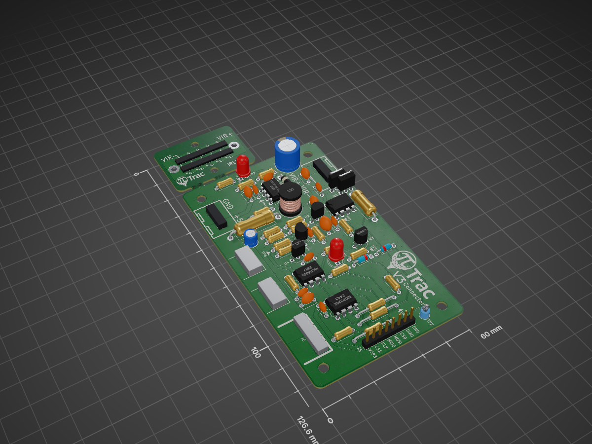
V3 Connector + IRLED is an open-source printed circuit board by PiTracLM, from the PiTracLM/PiTrac repository on GitHub, published under the GPL-2.0 licence. It is a 2-layer board of 60 × 126.6 mm with 151 parts on 55 nets, routed with 193 tracks and 500 vias.
It is built around the MC33063AP, MCP3202-CI/P and MCP4801-E/P, with the VSMA1085400, IRLU024NPBF and USB4085-GF-A among its other parts. Its parts include 23 resistors, 15 capacitors, 15 diodes, 6 connectors and 5 ICs.


Description:
A small PCB that supports:
The board uses high-speed opto-isolators to keep the power plane of the two Pi’s isolated from each other and from the 12V switching circuit.
The PCB itself can be manufactured fairly inexpensively from the fabrication outputs at place like https://jlcpcb.com/ and https://pcbway.com .
The PiTrac DIY golf launch monitor project is using this board to drive its infrared strobe light and to allow one Pi to trigger the shutter of a second Pi. This is all used to capture the stop-motion images for the monitor.
Please consider supporting this work and the DIY LM project here: https://ko-fi.com/PiTrac
Parts Needed for Assembly:
| Item | Qty | Reference(s) | Value | LibPart | Footprint / Details |
|---|---|---|---|---|---|
| 1 | 1 | J3 | ~ | USB B Micro Female Pinboard | The included pin headers can be used for the parts below |
| 2 | 2 | R1, R4 | 330 ohm R | Resistor (1/4 Watt) A decent assortment kit is here | Resistor_THT:R_Axial_DIN0207_L6.3mm_D2.5mm_P10.16mm_Horizontal |
| 3 | 2 | R2, R3 | 270 ohm R | Resistor (1/4 Watt) | Resistor_THT:R_Axial_DIN0207_L6.3mm_D2.5mm_P10.16mm_Horizontal |
| 4 | 3 | Shutter1, Strobe1, Sys1_GND1 | ~ | <These are just test-point holes to solder test wires into> | TestPoint:TestPoint_THTPad_2.5x2.5mm_Drill1.2mm |
| 5 | 1 | Sys1_Conn1 | ~ | 4 Pin Header | Connector_PinHeader_2.54mm:PinHeader_1x04_P2.54mm_Vertical |
| 6 | 1 | Sys2_Conn1 | ~ | 3 Pin Header | Connector_PinHeader_2.54mm:PinHeader_1x03_P2.54mm_Vertical |
| 7 | 2 | U2, U3 | H11L1 | Isolator:H11L1 | Package_DIP:DIP-6_W7.62mm |
| 8 | 1 | U4 | 74HC04 | 74xx:74HC04 | Package_DIP:DIP-14_W7.62mm_Socket |
| 9 | 1 | U5 | ~ | Dual_Mos_Driver_Module | Verdant_Custom_Footprint_Library:PCB Dual MOS Driver Module |
| 2 | 2.5M Bolt 2.5M Nut | These help mechanically tie down the USB-B power connector to the board | |||
| 2 | 6 - pin DIP socket | <Optional> A decent assortment kit is here | The opto-isolators and the hex inverter chip are the most likely to be blown up or injured by solder over-temps. So best to put them in sockets. | ||
| 1 | 14 - pin DIP socket <Optional> | <Optional> |
Note: A 5V USB-B power supply with a male micro-USB connector is currently necessary to run the board. The supply is used as an isolated, independent (downstream of a transformer) power plane to try to keep the Pi’s and the Pi Camera safe.
Final view of top/bottom of completed PCB:
NOTE: Don’t be like the people who made the above boards. For example, use flux-cleaner to get rid of the excess flux when you are done!
Assembly Notes (see supporting images of the board):
| Qty | Value | Footprint | References |
|---|---|---|---|
| 72 | , , , , , , , , , , , , , , , +56 | ||
| 10 | VSMA1085400 | Pi Connector Parts:VSMA1085400 | D6, D7, D8, D9, D10, D11, D12, D13, D14, D15 |
| 7 | 100nF | Capacitor_THT:C_Disc_D4.3mm_W1.9mm_P5.00mm | C3, C8, C10, C12, C13, C14, C15 |
| 4 | 1K | Resistor_THT:R_Axial_DIN0207_L6.3mm_D2.5mm_P7.62mm_Horizontal | R6, R8, R17, R22 |
| 4 | MountingHole | MountingHole:MountingHole_3.5mm | H1, H2, H3, H4 |
| 3 | 1uF | Capacitor_THT:C_Disc_D5.1mm_W3.2mm_P5.00mm | C2, C5, C11 |
| 2 | 0R | Resistor_THT:R_Axial_DIN0207_L6.3mm_D2.5mm_P15.24mm_Horizontal | R19, R23 |
| 2 | 0R | Resistor_THT:R_Axial_DIN0207_L6.3mm_D2.5mm_P7.62mm_Horizontal | R16, R20 |
| 2 | 2K | Resistor_THT:R_Axial_DIN0207_L6.3mm_D2.5mm_P7.62mm_Horizontal | R13, R21 |
| 2 | D_Schottky | Diode_THT:D_DO-35_SOD27_P7.62mm_Horizontal | D3, D4 |
| 2 | IRLU024NPBF | Package_TO_SOT_THT:TO-251-3_Vertical | Q1, Q2 |
| 2 | MountingHole | MountingHole:MountingHole_3.2mm_M3 | H6, H7 |
| 2 | MountingHole_Pad | MountingHole:MountingHole_2.2mm_M2_Pad | H5, H8 |
| 2 | USB4085-GF-A | Pi Connector Parts:USB4085-GF-A | J2, J5 |
| 2 | YK3210203000G | Pi Connector Parts:YK3210203000G | J1, J4 |
| 2 | ~ | Package_TO_SOT_THT:TO-92_Inline_Wide | Q4, U2 |
| 1 | 0R1 | Resistor_THT:R_Axial_DIN0414_L11.9mm_D4.5mm_P15.24mm_Horizontal | R10 |
| 1 | 0R150 | Resistor_THT:R_Axial_DIN0516_L15.5mm_D5.0mm_P20.32mm_Horizontal | R1 |
| 1 | 100nF | Capacitor_THT:C_Disc_D5.1mm_W3.2mm_P5.00mm | C7 |
| 1 | 100uF | Capacitor_THT:CP_Radial_D5.0mm_P2.00mm | C1 |
| 1 | 10K | Resistor_THT:R_Axial_DIN0207_L6.3mm_D2.5mm_P7.62mm_Horizontal | R18 |
| 1 | 10K | Resistor_THT:R_Axial_DIN0207_L6.3mm_D2.5mm_P15.24mm_Horizontal | R15 |
| 1 | 120R | Resistor_THT:R_Axial_DIN0207_L6.3mm_D2.5mm_P7.62mm_Horizontal | R9 |
| 1 | 180R | Resistor_THT:R_Axial_DIN0207_L6.3mm_D2.5mm_P10.16mm_Horizontal | R2 |
| 1 | 2K2 | Resistor_THT:R_Axial_DIN0207_L6.3mm_D2.5mm_P7.62mm_Horizontal | R4 |
| 1 | 2K49 | Resistor_THT:R_Axial_DIN0207_L6.3mm_D2.5mm_P7.62mm_Horizontal | R5 |
| 1 | 330uF | Capacitor_THT:CP_Radial_D10.0mm_P5.00mm | C6 |
| 1 | 33uH | Inductor_THT:L_Radial_D8.7mm_P5.00mm_Fastron_07HCP | L1 |
| 1 | 3K | Resistor_THT:R_Axial_DIN0207_L6.3mm_D2.5mm_P7.62mm_Horizontal | R14 |
| 1 | 4.7uF | Capacitor_THT:C_Disc_D6.0mm_W4.4mm_P5.00mm | C9 |
| 1 | 470pF | Capacitor_THT:C_Disc_D4.7mm_W2.5mm_P5.00mm | C4 |
| 1 | 604R | Resistor_THT:R_Axial_DIN0207_L6.3mm_D2.5mm_P7.62mm_Horizontal | R11 |
| 1 | 60K4 | Resistor_THT:R_Axial_DIN0207_L6.3mm_D2.5mm_P7.62mm_Horizontal | R3 |
| 1 | 6K | Resistor_THT:R_Axial_DIN0207_L6.3mm_D2.5mm_P7.62mm_Horizontal | R12 |
| 1 | 75K | Resistor_THT:R_Axial_DIN0207_L6.3mm_D2.5mm_P7.62mm_Horizontal | R7 |
| 1 | Conn_01x08 | Connector_PinHeader_2.54mm:PinHeader_1x08_P2.54mm_Vertical | J3 |
| 1 | LM4040LP-2.0 | Package_TO_SOT_THT:TO-92_Inline_Wide | U4 |
| 1 | LTL-307E | LED_THT:LED_D5.0mm | D5 |
| 1 | LTL-307G | LED_THT:LED_D5.0mm | D2 |
| 1 | MC33063AP | Package_DIP:DIP-8_W7.62mm | U1 |
| 1 | MCP3202 | Package_DIP:DIP-8_W7.62mm | U6 |
| 1 | MCP4801 | Package_DIP:DIP-8_W7.62mm | U5 |
| 1 | Q_NMOS | Package_TO_SOT_THT:TO-92_Inline_Wide | Q3 |
| 1 | SB150-E3/73 | Diode_THT:D_DO-41_SOD81_P10.16mm_Horizontal | D1 |
| 1 | TestPoint | TestPoint:TestPoint_Keystone_5010-5014_Multipurpose | TP2 |
| 1 | USB1125-GF-B | Pi Connector Parts:USB1125-GF-B | J6 |
| 1 | ~ | Package_DIP:DIP-8_W7.62mm | U3 |
PiTracLM/PiTrac
Launch monitor using low-cost raspberry pi and camera hardware to determine ball launch speed, angles and spin. See https://discord.gg/vGuyAAxXJH (permalink)

PiTracLM/PiTrac
Launch monitor using low-cost raspberry pi and camera hardware to determine ball launch speed, angles and spin. See https://discord.gg/vGuyAAxXJH (permalink)

PiTracLM/PiTrac
Launch monitor using low-cost raspberry pi and camera hardware to determine ball launch speed, angles and spin. See https://discord.gg/vGuyAAxXJH (permalink)

PiTracLM/PiTrac
Launch monitor using low-cost raspberry pi and camera hardware to determine ball launch speed, angles and spin. See https://discord.gg/vGuyAAxXJH (permalink)

Azzu-bear/sluggers-of-the-lost-goal
Autonomous ball-shooting competition robot (ECE 118 Mechatronics final project): PIC32 hierarchical state machines + ESP32-C3 sensor front end


baldengineer/Mega-IIe
Using the Mega II from a IIgs to make a Apple IIe compatible computer: The Mega IIe!

baldengineer/Banana-Plug-Adapters
Bench Power Supply Adapters for common connectors


FUEL4EP/HomeAutomation
Home Automation repository of FUEL4EP

im-alexis/Capstone-Project
Team Members: Javier Padilla, Alexis Torres, Ian Skillman, Kiet Le, Evan LeBel, Jesus Hernandez, Jaime Sanchez, Rodrigo Romero
It measures 60 × 126.6 mm and has 2 copper layers, 0.81 mm thick.
151 parts, built around the MC33063AP, MCP3202-CI/P, MCP4801-E/P and VSMA1085400. The full list of its parts is on this page, with links to each part's symbol and footprint where PCBKit's library has them.
From the PiTracLM/PiTrac repository on GitHub, at the commit this page was made from: the board is Hardware/KiCad Source Files/V3 Connector + IRLED.kicad_pcb and its schematic Hardware/Archive/Connector Board v0.2/PiTrac Connector Board.kicad_sch. PCBKit opens the board in the browser, with nothing to install.
Its repository publishes it under the GPL-2.0 licence: you may reuse it on that licence's terms (keep the author's notice, and for a copyleft licence share your changes alike).