Skip to the content
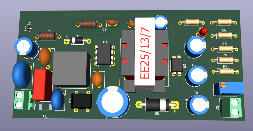
2 layers99.7 × 48.8 mmAC DC Wandler, the printed circuit board in 3D

Flyback AC-DC Converter (230V AC to 12V DC) — Full SMPS design using VIPer22A PWM Controller. Schematic, PCB layout & 3D render in KiCad.

Size
99.7 × 48.8 mm
Copper layers
2
Thickness
1.6 mm
Parts
34
Nets
24
Pads
89
Tracks, vias
358, 0
Routed
Yes
KiCad
KiCad 10.0 (file 20260206)
Created
26 Jun 2026
Updated
28 Aug 2026

Overview

AC DC Wandler is an open-source printed circuit board by MoElashmawi, from the MoElashmawi/Flyback-AC-DC-Converter repository on GitHub, published under the MIT licence. It is a 2-layer board of 99.7 × 48.8 mm with 34 parts on 24 nets, routed with 358 tracks and 0 vias.

It is built around the EL817, VIPER22ADIP-E and 3MM LED发光二极管90度弯脚, with the FR107, KBP206 and SB360 among its other parts. Its parts include 11 capacitors, 7 resistors, 4 diodes, 3 ICs and 2 connectors.

Main components

6

README

README.md

Flyback AC-DC Converter — 12 V SMPS

KiCad 10.0.1 | Mohamed Elashmawi | TU Dortmund

A complete Switch-Mode Power Supply (SMPS) designed from scratch using the flyback topology, converting 230 VAC mains input to a regulated 12 VDC output. The project covers full schematic design, PCB layout and 3D validation.

⚠️ Safety notice — This circuit operates directly on mains voltage (230 VAC). Schematic and layout are published for educational and design-reference purposes only. Do not build or test it without proper knowledge, equipment and safety precautions.


📷 Overview

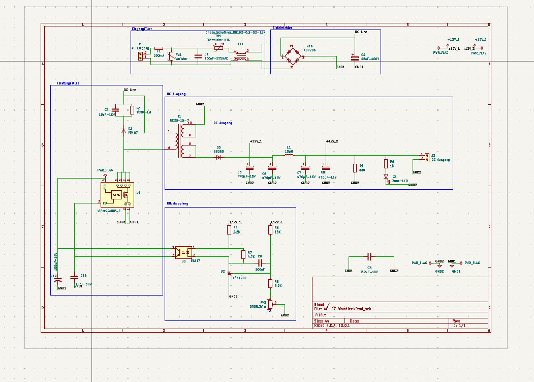
Schematic

Schematic

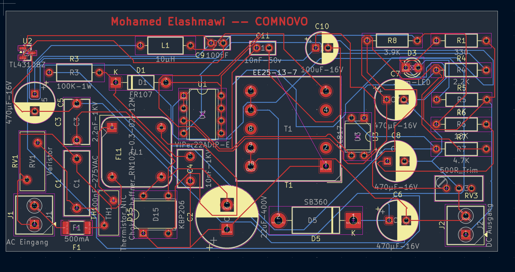
PCB Layout

PCB Layout

3D Render

3D Render


⚡ Specifications

ParameterValue
Input voltage230 VAC, 50 Hz
Output voltage12 VDC
TopologyFlyback (isolated SMPS)
PWM controllerVIPer22A (DIP-8)
TransformerEE25-13-7
Bridge rectifierKBP206
Output diodeSB360 (Schottky)
Feedback / isolationEL817 optocoupler + TL431
Input protectionVaristor + NTC thermistor + 500 mA fuse
EMI filterSchaffner RN102-0.3-02-12M

🔧 Circuit Architecture

The design is split into four functional blocks.

1. Input Filter (Eingangsfilter)

RefComponentFunction
RV1Varistor 275 VACOvervoltage / surge protection
TH1NTC thermistorInrush current limiting at start-up
FL1Schaffner RN102Common-mode noise suppression
F1Fuse 500 mAShort-circuit protection
C1X-capacitor 100 nF / 275 VACDifferential-mode noise filtering

2. Power Stage (Leistungsstufe)

RefComponentFunction
D15KBP206Full-wave rectification
C222 µF / 400 VDC bus smoothing
U1VIPer22AIntegrated MOSFET + PWM control
T1EE25-13-7Galvanic isolation & energy transfer
R3, C3, D1RCD snubberDrain spike clamping

3. DC Output (DC Ausgang)

RefComponentFunction
D5SB360 SchottkyLow forward-drop rectification
L110 µHOutput ripple reduction
C5–C8470 µF / 16 VOutput voltage smoothing
D3Status LEDPower-on indication

4. Feedback / Regulation (Rückkopplung)

RefComponentFunction
U2TL431Programmable precision shunt regulator
U3EL817 optocouplerGalvanic isolation of the feedback signal
RV3500 Ω trimmerOutput voltage fine adjustment
R4–R7Divider networkOutput voltage sensing

📐 Key Design Decisions

RCD snubber

The flyback topology generates high-voltage spikes on the MOSFET drain at turn-off, caused by the leakage inductance of the transformer. An RCD clamp (R3 = 100 kΩ, C3 = 2.2 nF / 1 kV, D1 = FR107) absorbs this energy and protects the MOSFET integrated in the VIPer22A.

Optocoupler feedback loop

The EL817 combined with the TL431 shunt regulator forms a stable, isolated feedback loop, keeping the 12 V output regulated across input voltage and load variations while maintaining the isolation barrier.

EMI and input filtering

A Schaffner common-mode choke (FL1) together with the X-capacitor (C1) and the NTC thermistor (TH1) forms the input filter, limiting conducted emissions back into the mains.


📦 Bill of Materials (key components)

ReferenceComponentValue / Part number
U1PWM controllerVIPer22ADIP-E
U2Shunt regulatorTL431DBZ
U3OptocouplerEL817
T1TransformerEE25-13-7
D1Fast recovery diodeFR107
D5Schottky diodeSB360
D15Bridge rectifierKBP206
FL1EMI filterSchaffner RN102-0.3-02-12M
RV1Varistor275 VAC
TH1NTC thermistor—
C2Bulk capacitor22 µF / 400 V
C5–C8Output capacitors470 µF / 16 V
RV3Trimmer500 Ω

📁 Repository Structure

text
├── AC-DC Wandler.kicad_pro   KiCad project
├── AC-DC Wandler.kicad_sch   Schematic
├── AC-DC Wandler.kicad_pcb   PCB layout
├── fabrication/              Gerber & drill files
└── images/                   Schematic, layout and 3D render

🎓 What I Learned

  • Complete SMPS design flow, from topology selection to manufacturing files
  • How the VIPer22A integrated PWM controller works and how to design around it
  • Sizing an RCD snubber to protect the MOSFET in a flyback converter
  • Designing an isolated feedback loop with TL431 and optocoupler
  • PCB layout practice for mixed high-voltage / low-voltage boards
  • Grounding strategies to reduce EMI in switched-mode supplies
  • Using STEP 3D models in KiCad to validate component footprints

👤 Author

Mohamed Elashmawi — B.Sc. Elektrotechnik und Informationstechnik, TU Dortmund 📫 mohamednehmedo716@gmail.com

📄 License

MIT — free to use, adapt and learn from. Credits appreciated.

Parts

34
QtyValueFootprintReferences
4470μF-16VCapacitor_THT:CP_Radial_D8.0mm_P3.50mmC5, C6, C7, C8
1100K-1WInductor_THT:L_Axial_L7.0mm_D3.3mm_P10.16mm_Horizontal_Fastron_MICCR3
1100nFCapacitor_THT:C_Disc_D5.0mm_W2.5mm_P2.50mmC9
1100nF-275VACCapacitor_THT:C_Rect_L13.0mm_W5.0mm_P10.00mm_FKS3_FKP3_MKS4C1
1100uF-16VCapacitor_THT:CP_Radial_D6.3mm_P2.50mmC10
110nF-1KVCapacitor_THT:C_Disc_D7.5mm_W5.0mm_P5.00mmC4
110nF-50vCapacitor_THT:C_Disc_D5.0mm_W2.5mm_P2.50mmC11
110µHInductor_THT:L_Axial_L7.0mm_D3.3mm_P10.16mm_Horizontal_Fastron_MICCL1
118KResistor_THT:R_Axial_DIN0207_L6.3mm_D2.5mm_P10.16mm_HorizontalR6
11KResistor_THT:R_Axial_DIN0207_L6.3mm_D2.5mm_P10.16mm_HorizontalR5
12.2KResistor_THT:R_Axial_DIN0207_L6.3mm_D2.5mm_P10.16mm_HorizontalR4
12.2nF-1KVCapacitor_THT:C_Disc_D9.0mm_W5.0mm_P7.50mmC3
122uF-400VCapacitor_THT:CP_Radial_D12.5mm_P5.00mmC2
13.9KResistor_THT:R_Axial_DIN0207_L6.3mm_D2.5mm_P10.16mm_HorizontalR8
1330Resistor_THT:R_Axial_DIN0207_L6.3mm_D2.5mm_P10.16mm_HorizontalR1
13mm-LEDLED_THT:LED_D3.0mmD3
14.7KResistor_THT:R_Axial_DIN0207_L6.3mm_D2.5mm_P10.16mm_HorizontalR7
1500R_TrimPotentiometer_THT:Potentiometer_Bourns_3296W_VerticalRV3
1500mAFuse:Fuse_2010_5025MetricF1
1AC EingangTerminalBlock_Phoenix:TerminalBlock_Phoenix_MKDS-1-2-3.81_1x02_P3.81mm_HorizontalJ1
1Choke_Schaffner_RN102-0.3-02-12MInductor_THT:Choke_Schaffner_RN102-04-14.0x14.0mmFL1
1DC AusgangTerminalBlock_Phoenix:TerminalBlock_Phoenix_MKDS-1-2-3.81_1x02_P3.81mm_HorizontalJ2
1EE25-13-7Transformer_THT:Transformer_Myrra_EF20_7408xT1
1EL817Package_DIP:DIP-4_W7.62mmU3
1FR107Diode_THT:D_DO-41_SOD81_P10.16mm_HorizontalD1
1KBP206Diode_THT:Diode_Bridge_DIP-4_W7.62mm_P5.08mmD15
1SB360Diode_THT:D_DO-201AD_P15.24mm_HorizontalD5
1TL431DBZPackage_TO_SOT_SMD:SOT-23U2
1Thermistor_NTCVaristor:RV_Disc_D9mm_W4mm_P5mmTH1
1VIPer22ADIP-EPackage_DIP:DIP-8_W7.62mmU1
1VaristorVaristor:RV_Disc_D12mm_W5mm_P7.5mmRV1

Similar boards

  • 2 layers46.4 × 80 mm3Phase, the printed circuit board in 3D

    3Phase

    eauel/openzmeter

    openzmeter (oZm) is an Open Source system designed for power quality analysis and smart energy metering in power networks. It has been designed to comply with international standards IEC 61000-4-30 and EN 50160.

    153 partsGPL-3.0
  • 2 layers71.1 × 64.1 mmBikeLights, the printed circuit board in 3D

    BikeLights

    jkasari/bikeLightsPCB

    The Schematic and PCB layout for the bikelights on my commuter bike.

    24 parts
  • 2 layers71.2 × 28.4 mmTryout1, the printed circuit board in 3D

    Tryout1

    ctrl-z3d/pcb-designs

    A personal archive of PCB projects I've designed and built along the way. Schematics, board layouts, manufacturing files, and notes.

    9 parts1
  • 2 layers85 × 128.5 mmMiniVerb, the printed circuit board in 3D

    MiniVerb

    benjiaomodular/MiniVerb

    A through-hole reverb module for Eurorack based around the Daisy Seed by Electrosmith

    59 parts28MIT
  • 2 layers253.2 × 203 mmPegasus2023, the printed circuit board in 3D

    Pegasus2023

    NeilsVintageComputers/1981_Aamber-Pegasus-2023-Revival

    My first computer, this is a replica I produced from the original schematics using original old components.

    156 partsUnlicense
  • 2 layers180 × 40 mmEuroPowerBoard, the printed circuit board in 3D

    EuroPowerBoard

    benjiaomodular/EuroPowerBoard

    This is a busboard for Eurorack synths with support for IDC and JST connectors

    29 parts8CC-BY-SA-4.0
  • 2 layers180 × 58 mmHandheld sstc, the printed circuit board in 3D

    Handheld sstc

    automagicle/handheld-sstc

    A handheld SSTC project on PCB, designed for a large magic wand form factor, entirely powered from 8s 18650. Uses direct secondary feedback with gate driver and MOSFETs, and 555 interrupter

    66 parts1

Questions

How big is the AC DC Wandler PCB?

It measures 99.7 × 48.8 mm and has 2 copper layers, 1.6 mm thick.

What parts does the AC DC Wandler use?

34 parts, built around the EL817, VIPER22ADIP-E, 3MM LED发光二极管90度弯脚 and FR107. The full list of its parts is on this page, with links to each part's symbol and footprint where PCBKit's library has them.

Where can I download the AC DC Wandler KiCad files?

From the MoElashmawi/Flyback-AC-DC-Converter repository on GitHub, at the commit this page was made from: the board is AC-DC Wandler.kicad_pcb and its schematic AC-DC Wandler.kicad_sch. PCBKit opens the board in the browser, with nothing to install.

Can I use the AC DC Wandler design in my own project?

Its repository publishes it under the MIT licence: you may reuse it on that licence's terms (keep the author's notice, and for a copyleft licence share your changes alike).