


2 layers128 × 41.5 mm
Weather station ext
rbat05/SolarWeatherStation
Self-sustaining weather monitoring system with dual-node architecture.
16 parts2GPL-3.0
RescueMesh uses a Long Range Communication System to send SOS signals to a central database where the rescue data is sent even without any mobile connectivity.
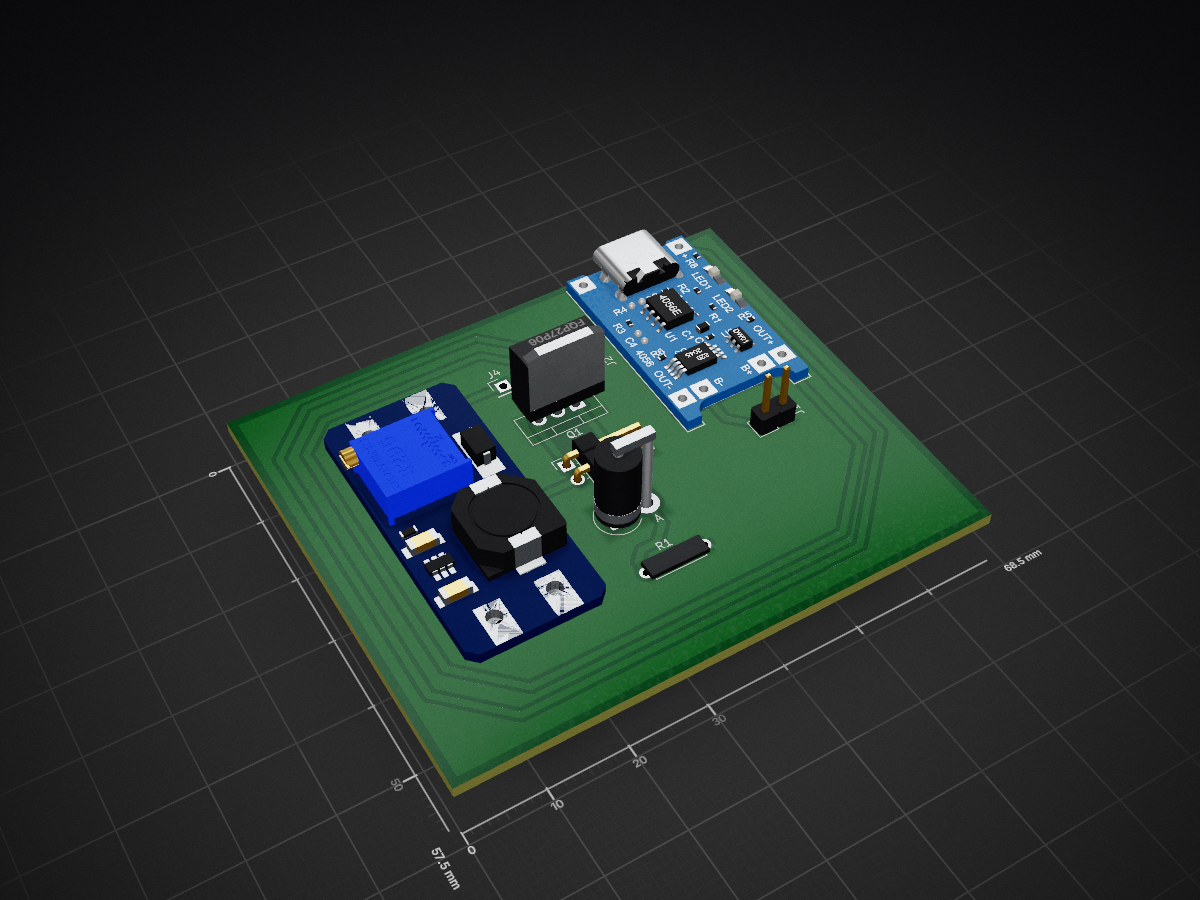
Load Sharing PCB is an open-source printed circuit board by HiranGeeth, from the HiranGeeth/RescueMesh-Disaster-Rescue_Long-Range-Communication-System repository on GitHub, published under the MIT licence. It is a 2-layer board of 68.5 × 57.5 mm with 8 parts on 8 nets, routed with 54 tracks and 0 vias.
It is built around the FQP27P06 and TP4056. Its parts include 5 connectors, 1 resistor, 1 diode and 1 transistor.
🌊 Flood Data Collecting & Rescue-Aided LoRaWAN System

This project implements a low-power, long-range LoRaWAN system for flood data collection and emergency rescue notifications.
Using ESP32 microcontrollers paired with AS32-TTL-100 LoRa modules, the system enables wireless sensor networking, SOS message broadcasting, and remote monitoring with low latency and high reliability.
The firmware is modular and structured, supporting incremental testing from GPIO/UART sanity checks to full production-ready emergency node firmware.
ADDH = 0x00, ADDL = 0x00SPEED = 0x1A (9600 bps, 2.4 kbps air)CHAN = 0x17 (433 MHz)OPTION = 0x40 (transparent, push-pull, 250 ms wake, max TX power)git clone https://github.com/HiranGeeth/RescueMesh-Flood_Rescue_LoRa_System.git
| Qty | Value | Footprint | References |
|---|---|---|---|
| 1 | 10k | Resistor_THT:R_Axial_DIN0207_L6.3mm_D2.5mm_P7.62mm_Horizontal | R1 |
| 1 | 1N5822 Diode | Diode_THT:D_DO-201AD_P3.81mm_Vertical_AnodeUp | D1 |
| 1 | Conn_01x01 | Connector_PinHeader_2.54mm:PinHeader_1x01_P2.54mm_Vertical | J4 |
| 1 | Conn_01x02 | Connector_PinHeader_2.54mm:PinHeader_1x02_P2.54mm_Vertical | J1 |
| 1 | FQP27P06 | Package_TO_SOT_THT:TO-220-3_Vertical | Q1 |
| 1 | MT3608 module | MT3608:MT3608_module | J3 |
| 1 | Switch | Connector_PinHeader_2.54mm:PinHeader_1x02_P2.54mm_Horizontal | J5 |
| 1 | TP4056 | TP4056_charging_module:TP4056-18650 | J2 |
rbat05/SolarWeatherStation
Self-sustaining weather monitoring system with dual-node architecture.


mattronix/battery-board
KiCad hardware project for the battery-to-radio interface of an AN/PRC‑152(A) reproduction radio. It contains two small PCBs that mate through spring‑loaded pogo‑pin contacts, plus a shared custom KiCad footprint…

mattwach/portable_led_lamp
Contains firmware, schematics and 3D models for a LED lamp that can accept a wide range of voltages.

pietwauters/esp32_scoring_device_hardware
Hardware files for the scoring device

xHain-hackspace/xDoorPiHat
Schematics and Boardfiles for PiHat that opens and closes the xDoor


borisg912/3DNA
This project creates a flat cylindrical DNA model with: - Magnetic DNA bases with color-coded NeoPixel LEDs and unique resistor values for identification - Interactive base pairing game that validates correct DNA base…
It measures 68.5 × 57.5 mm and has 2 copper layers, 1.6 mm thick.
8 parts, built around the FQP27P06 and TP4056. The full list of its parts is on this page, with links to each part's symbol and footprint where PCBKit's library has them.
From the HiranGeeth/RescueMesh-Disaster-Rescue_Long-Range-Communication-System repository on GitHub, at the commit this page was made from: the board is hardware/Power Path Management Circuit/pcb/Load Sharing PCB.kicad_pcb and its schematic hardware/Power Path Management Circuit/Shematics/Load Sharing PCB.kicad_sch. PCBKit opens the board in the browser, with nothing to install.
Its repository publishes it under the MIT licence: you may reuse it on that licence's terms (keep the author's notice, and for a copyleft licence share your changes alike).