

4 layers15.2 × 27.2 mm
Riotee Module
NessieCircuits/Riotee_Module
Design Resources for the Riotee Module
93 parts1CERN-OHL-W-2.0
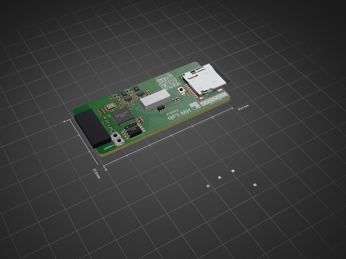
WebScreen PCB designs, BOM and other manufacturing files.
Display pcb is an open-source printed circuit board by HW-Lab-Hardware-Design-Agency, from the HW-Lab-Hardware-Design-Agency/WebScreen-PCB repository on GitHub, published under the CERN-OHL-P-2.0 licence. It is a 4-layer board of 60.6 × 27.6 mm with 93 parts on 104 nets, routed with 1,140 tracks and 406 vias.
It is built around the ESP32-S3R8, SY8089A1AAC and W25Q128JVSIQ, with the USBLC6-2SC6, CGA0402X5R226M100GT and CGA2B3X7R1V104KT0Y0F among its other parts. Its parts include 37 capacitors, 22 resistors, 5 ICs, 5 inductors and 3 connectors. It belongs with the lEDs and displays boards and the ESP32 boards of this library.



WebScreen-PCB is the design of a printed circuit board (PCB) for the WebScreen, a display device with a custom stand. This project is developed by HW Lab - Hardware Design Agency and aims to optimize the integration and functionality of the WebScreen in various applications.
This project is open source. See the LICENSE file for details.
PCBWay top quality PCBA service made this project possible: fast, precise, and super reliable. We highly recommend them to all creators out there, and we’ll definitely keep working with them for future builds.
For inquiries or contributions, please contact the development team through the repository issues or via email.
| Qty | Value | Footprint | References |
|---|---|---|---|
| 10 | 1uF | Capacitor_SMD:C_0603_1608Metric | C2, C5, C6, C7, C10, C14, C15, C20, C32, C33 |
| 10 | 22uF | Capacitor_SMD:C_0402_1005Metric | C18, C22, C24, C25, C27, C28, C30, C34, C36, C37 |
| 8 | 10k | Resistor_SMD:R_0402_1005Metric | R1, R2, R3, R4, R7, R10, R12, R20 |
| 6 | 100nF | Capacitor_SMD:C_0402_1005Metric_Pad0.74x0.62mm_HandSolder | C1, C8, C9, C12, C13, C19 |
| 4 | 0R | Resistor_SMD:R_0402_1005Metric | R8, R18, R19, R32 |
| 4 | 100nF | Capacitor_SMD:C_0402_1005Metric | C23, C26, C29, C35 |
| 3 | 100k | Resistor_SMD:R_0402_1005Metric | R11, R13, R14 |
| 3 | 1k | Resistor_SMD:R_0603_1608Metric_Pad0.98x0.95mm_HandSolder | R15, R16, R23 |
| 3 | B3U-1000P | smd-non-ipc:B3U-1000P | SW1, SW2, SW3 |
| 3 | GREEN | LED_SMD:LED_0603_1608Metric | DS1, DS2, DS3 |
| 2 | 1.8pF | Capacitor_SMD:C_0201_0603Metric | C16, C17 |
| 2 | 1uH | smd-non-ipc:BR2518_YDN | L4, L5 |
| 2 | 4k99 | Resistor_SMD:R_0402_1005Metric | R5, R6 |
| 2 | 6.8pF | Capacitor_SMD:C_0402_1005Metric | C21, C31 |
| 2 | NetTie_2 | NetTie:NetTie-2_SMD_Pad0.5mm | NT1, NT2 |
| 2 | SY8089A1AAC | smd-non-ipc:SOT95P285X130-5N | U2, U4 |
| 1 | +3V3 | TestPoint:TestPoint_Pad_D1.0mm | TP4 |
| 1 | +4V6 | TestPoint:TestPoint_Pad_D1.0mm | TP2 |
| 1 | +5V | TestPoint:TestPoint_Pad_D1.0mm | TP1 |
| 1 | 10uF | Capacitor_SMD:C_0402_1005Metric | C11 |
| 1 | 12pF | Capacitor_SMD:C_0402_1005Metric_Pad0.74x0.62mm_HandSolder | C4 |
| 1 | 15pF | Capacitor_SMD:C_0402_1005Metric_Pad0.74x0.62mm_HandSolder | C3 |
| 1 | 2.7nH | Inductor_SMD:L_0201_0603Metric | L3 |
| 1 | 22k | Resistor_SMD:R_0402_1005Metric | R17 |
| 1 | 22nH | Inductor_SMD:L_0402_1005Metric | L1 |
| 1 | 2nH | Inductor_SMD:L_0402_1005Metric | L2 |
| 1 | 33FXRH-SM1-GAN-TF | smd-non-ipc:33FXRH-SM1-GAN-TF | J8 |
| 1 | 40MHz | smd-non-ipc:SMD32324-4P | Y1 |
| 1 | 64k9 | Resistor_SMD:R_0402_1005Metric | R9 |
| 1 | ESP32-S3R8 | smd-non-ipc:QFN40P700X700X90-57N-D | IC1 |
| 1 | GND | TestPoint:TestPoint_Pad_D1.0mm | TP5 |
| 1 | LOGO | smd-non-ipc:logo_HWLabs | G*** |
| 1 | LOGO | smd-non-ipc:QR_webscreenCC | G*** |
| 1 | LOGO | logo:OSHWA_Certification.kicad_sym | G*** |
| 1 | LOGO | smd-non-ipc:uk-ca-CE_logo | G*** |
| 1 | LOGO | smd-non-ipc:pcbway_logo | G*** |
| 1 | Micro_SD_Card_Det_Hirose_DM3AT | smd-non-ipc:TF PUSH | J1 |
| 1 | PCB Antenna 2.4GHz | smd-non-ipc:pcb_antenna_2_4GHz | AE1 |
| 1 | USB C | paltatech:USB_C_Receptacle_HCTL_HC019-1E1H1A103-0HR | J2 |
| 1 | USBLC6-2SC6 | Package_TO_SOT_SMD:SOT-23-6 | U5 |
| 1 | W25Q128JVSIQ | Package_SO:SOIC-8W_5.3x5.3mm_P1.27mm | U1 |
The 91 most common of 93 parts.
NessieCircuits/Riotee_Module
Design Resources for the Riotee Module

JasonHEngineering/DIY-Robot-Arm-V3
1) Along with using with TMC2209 motor drivers, I have removed R8, R15, R16, R17, R18, R19 because the R value was accidentally too high. I have shorted R8, R16, R17, and left open R15, R18, R19.


alph4345/test
TrinketCore puts everything a small rechargeable gadget needs on one 40 × 60 mm board, ready to order assembled from PCBWay:


azais-corentin/espion
Multi-camera IR marker tracking: ESP32-P4/C5 firmware, Rust host, KiCad hardware

ChrisHayward-dev/SapphireKicad
See the LastProduction branch for the most current revision

gallicchio/AMOD-and-RFMOD
The tutorial's 2x12 adapter (/mudd/133electronics/icepi-zero-dac-adc/adapterboard/) with a 2 x 6 right-angle Pmod socket on a 15 mm extension of its right-hand end, so an Icepi Zero can drive AMOD-A's and RF-MOD's Pmod…
It measures 60.6 × 27.6 mm and has 4 copper layers, 1.6 mm thick.
93 parts, built around the ESP32-S3R8, SY8089A1AAC, W25Q128JVSIQ and USBLC6-2SC6. The full list of its parts is on this page, with links to each part's symbol and footprint where PCBKit's library has them.
From the HW-Lab-Hardware-Design-Agency/WebScreen-PCB repository on GitHub, at the commit this page was made from: the board is kicad_project/Display_pcb.kicad_pcb and its schematic kicad_project/Display_pcb.kicad_sch. PCBKit opens the board in the browser, with nothing to install.
Its repository publishes it under the CERN-OHL-P-2.0 licence: you may reuse it on that licence's terms (keep the author's notice, and for a copyleft licence share your changes alike).