Skip to the content
4 layers162.2 × 100 mmDigital, the printed circuit board in 3D

Open-source acquisition trigger

Size
162.2 × 100 mm
Copper layers
4
Thickness
1.6 mm
Parts
438
Nets
420
Pads
1,560
Tracks, vias
3,649, 1,885
Pours
25
Routed
Yes
KiCad
KiCad 9.0 (file 20241229)
Created
12 Jul 2025
Updated
27 Mar 2026

Overview

Digital is an open-source printed circuit board by Dawson-HEP, from the Dawson-HEP/opentrig repository on GitHub, published under the EPL-2.0 licence. It is a 4-layer board of 162.2 × 100 mm with 438 parts on 420 nets, routed with 3,649 tracks and 1,885 vias.

It is built around the ICE40HX4K-TQ144, RP2040 and 74HC244D, with the MCP4728-E/UN, CH224K and W25Q32JVZPIQ among its other parts. Its parts include 135 resistors, 116 capacitors, 45 connectors, 38 ICs and 37 diodes. It belongs with the RP2040 and FPGA and CPLD boards of this library.

Main components

12

README

README.md

opentrig

open-source trigger system

An open-source, integrated, particle physics data acquisition system (DAQ).

Designed to interface with timing systems controlled by the AIDA-2020 TLU. Up to 24 digital trigger channels with variable-gain threshold setting.

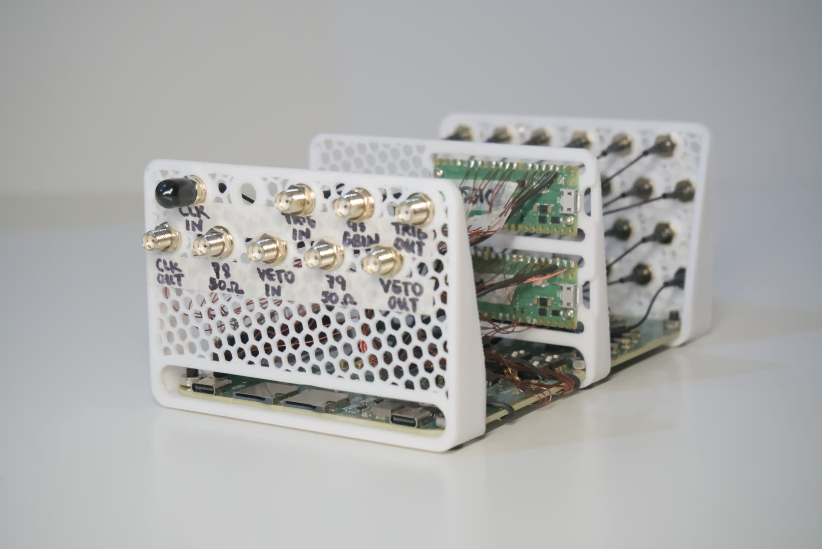
Main picture of opentrig

Features

  • 144 MHz internal FPGA clock, and timing resolution
  • 24 digital trigger channels with variable gain
  • Input voltage range 3.3V-5V
  • TTL level compatible clock, trigger, input and output
  • AIDA-2020 TLU synchronous AIDA mode (page 31) compatible FPGA

Hardware Overview

Schematics can be found here.

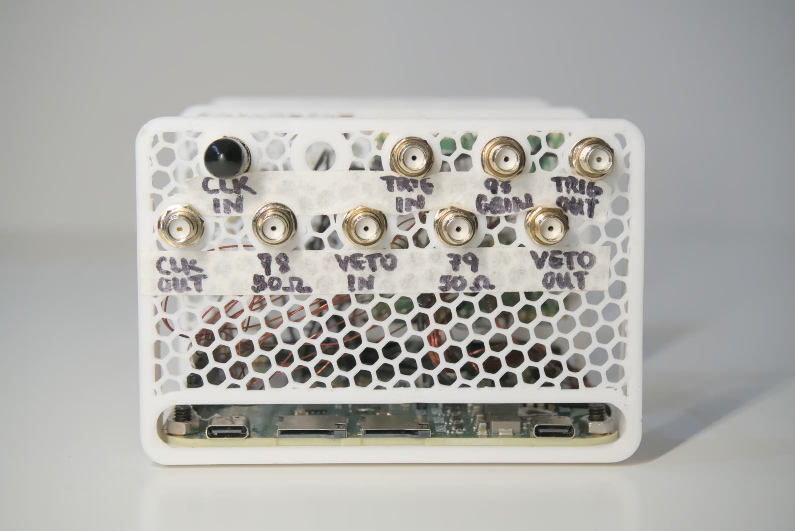
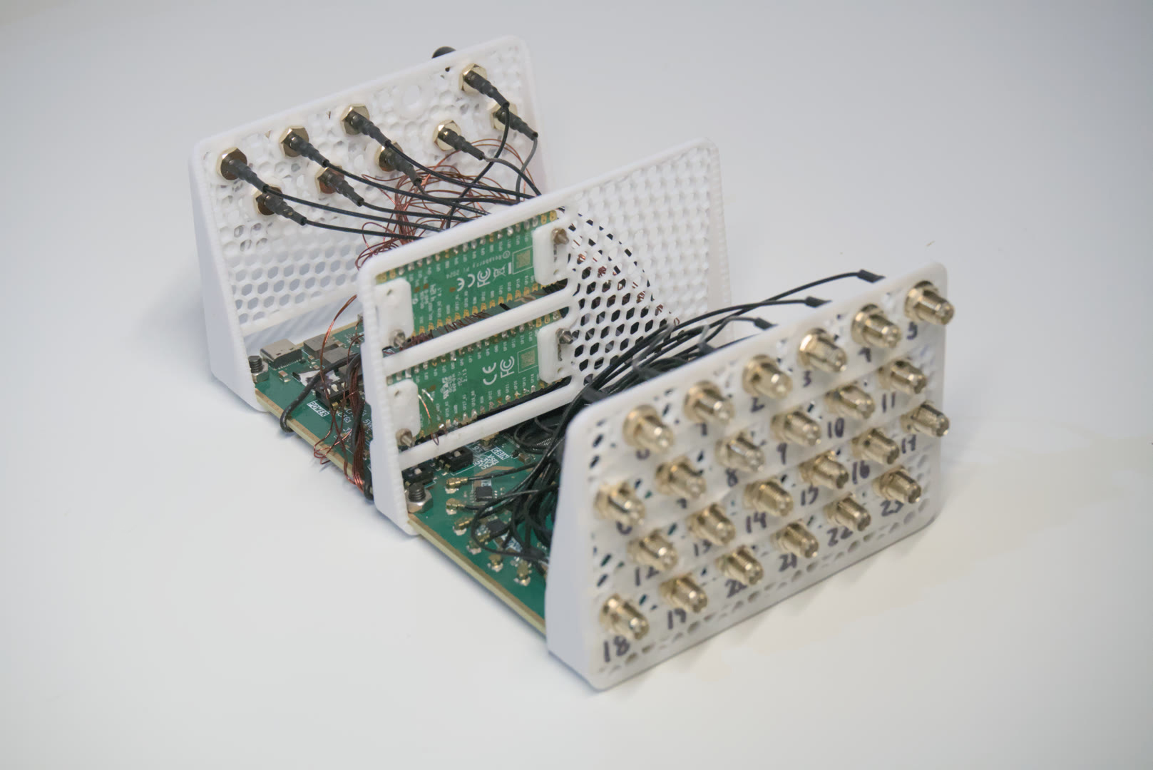
Front panel IO (left)

  • Input clock signal (<40 MHz square wave)
  • Output clock signal (120 MHz square wave, 3.3V TTL, <0.5% jitter, phase-locked)
  • Input/output trigger (3.3V TTL)
  • Input/output veto (3.3V TTL)
  • Extra 50R impedance-matched inputs

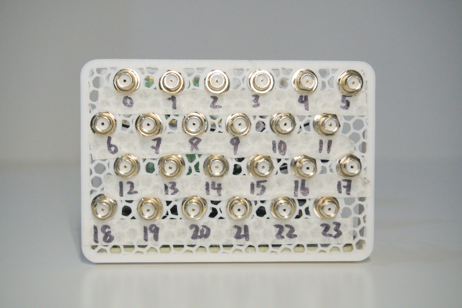
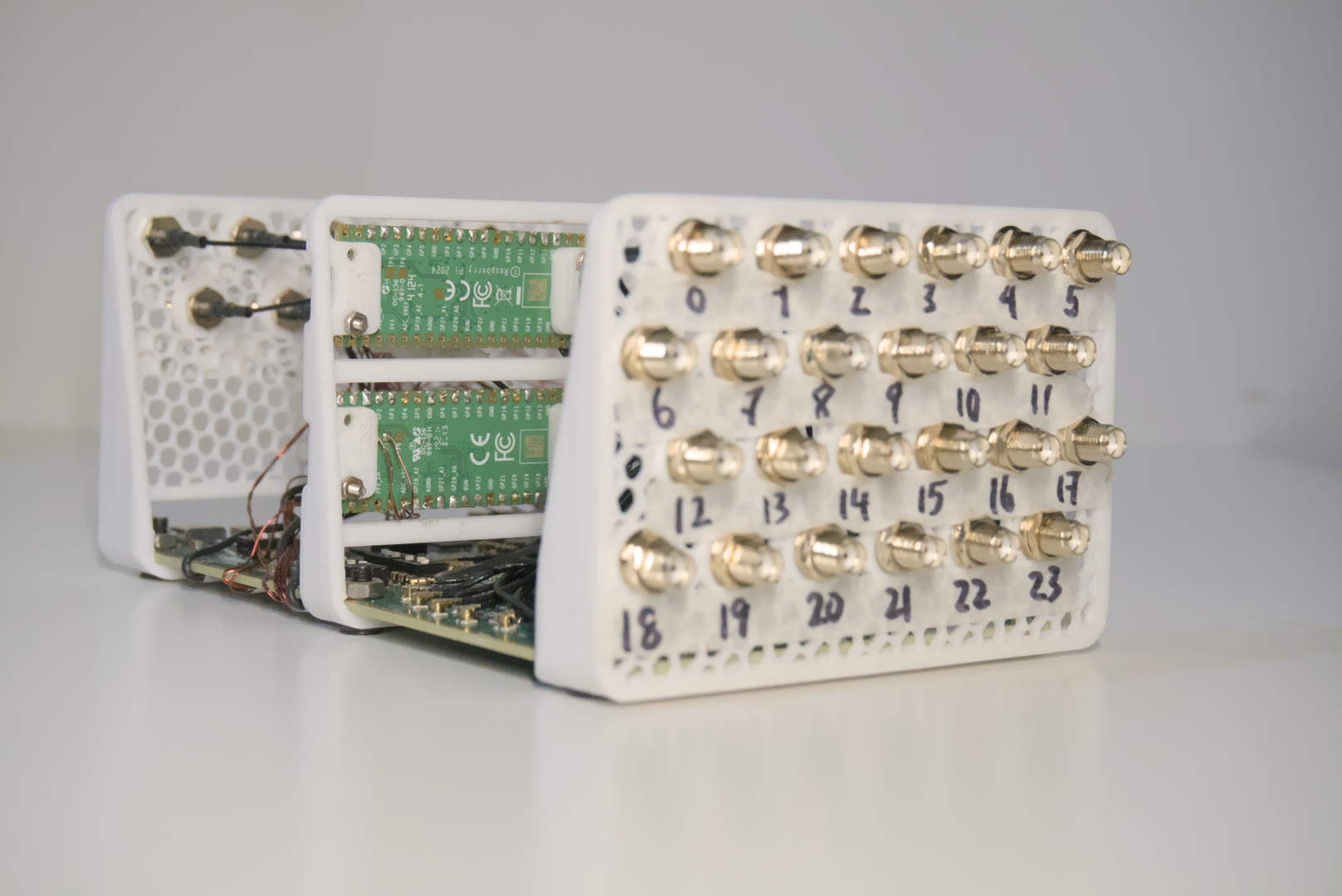
Back panel (right)

  • 24 channel digital inputs, with variable trigger thresholds (1.024 mV steps):
    • 0.000V-2.000V (1x gain)
    • 0.000V-4.000V (2x gain)

Internal components

  • Low drift 5.000V reference (TI REF5050AIR)
  • 12 high-speed thresholding comparators (TI TLV3502)
  • 120 MHz MCU (RP2040)
  • FPGA (Lattice ICE40 HX4K)

Front panel Back panel

Trigger Architecture

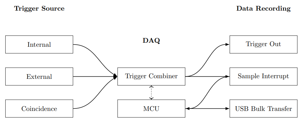
The opentrig system is a 24-channel, synchronous data acquisition platform compatible with EUDAQ2-compatible beamline trigger systems. Each channel digitizes an analog falling-edge into a digital rising-edge depending on a threshold set by independent digital-to-analog converters (DACs). Three trigger sources are fed into a selectable OR-ing gate, which allows for the selection of the interrupt source(s) for sample recording.

Fig 1

The trigger combiner vetoes priority in regards to the inputs of selected trigger sources, and assigns FPGA SPI bandwidth to the microcontroller (MCU) for processing and sampling. An active-high trigger output is asserted with controllable duration and delay in reference to the trigger sources. The sample interrupt interacts with the MCU in order to stream data live through the USB Type-C interface across bulk transfer.

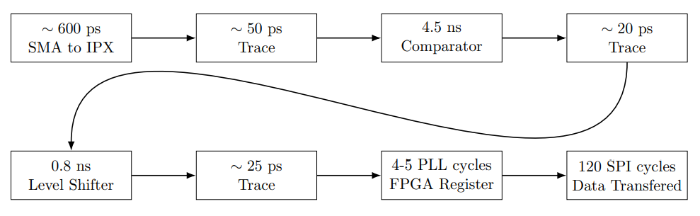
Trigger Delay

The delays incurred by the trigger is synchronized across channels by means of length matching. The largest skew is a result of level shifting: indeed up to $\pm 0.3$ ns across channels. No significant differences are measured in practice. FPGA gate skew is below the delays of level shifting, and are thus negligible in practice. PCB traces are delay-matched to within $\pm0.01$ mm. Given the assumption that channels are synchronized between each other, the input-output delay needs to be considered.

Fig 2

Clocks

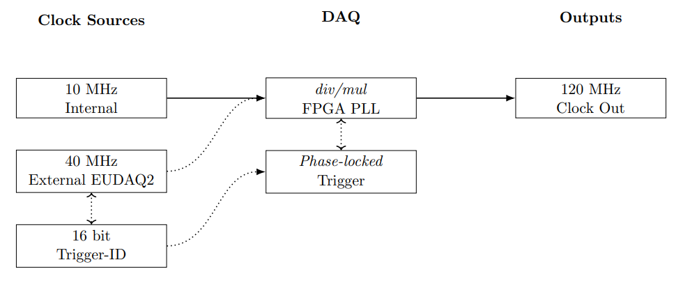
The FPGA PLL is synchronized to a sampling clock of $120$ MHz, while the SPI clock transfers data at a rate of $5$ MHz. The user can select an internal clock input or an external clock input, both requiring different PLL clock dividers to achieve the full sampling rate at $120$ Msps.

Fig 3

Clocks are phase-aligned by phase-locked-loop (PLL). An internal clock can be generated for the independent functioning of the DAQ. Proper PLL clock dividers and multipliers must be set to achieve the target $120$ MHz. An external clock compliant to EUDAQ2 trigger systems, such as the AIDA-2020 TLU, can be synchronized to \textit{opentrig}. A 16-bit trigger-ID can be read synchronously by the phase-locked external trigger module, which will be recorded upon the assertion of a sample interrupt.

Voltage Levels

The 24 analog inputs are limited to a voltage range of $-0.30$ V to $+5.30$ V on wide-gain mode, and $-0.30$ V to $+3.30$ V on limited-gain mode. A voltage beyond permissible levels may cause irreversible damage to thresholding comparators, whose inputs are directly connected to SMA connectors.

The digital signals are high-impedance or $50 \Omega$ terminated depending on the label, and function on $3.3$ V CMOS voltage levels. The push-pull drivers have weak drive capabilities; therefore, only small digital loads may be attached with matched impedance.

Directory Structure

The hardware is designed in KiCad for the digital trigger front-end and mechanical layout, while the firmware and control utilities are written in Rust using the Embassy embedded framework. The FPGA subsystems are written in pure Verilog with the Yosys open-source toolchain, and Project Icestorm's bitstream documentation.

text
opentrig/
├── hardware/ # KiCad hardware design
│   ├── fab/ # Fabrication files and gerbers
│   ├── logos.pretty/ # Custom logo footprints and graphics
│   └── digital.pretty/ # Custom digital footprints and component libraries
│
├── opentrig/ # Core DAQ firmware
│   ├── src/ # Source code (Rust + Embassy)
│   │   └── fpga/ # FPGA interface and logic modules
│   └── target/ # Compiled firmware output and build artifacts
│
├── cli/ # Command-line interface for control and configuration via host computer
│   ├── src/ # Rust source for CLI utilities
│   └── target/ # Compiled CLI binaries
│
├── tests/ # Automated and hardware-in-the-loop test framework
│   ├── src/ # Unit and integration test sources
│   └── target/ # Compiled test binaries and reports
│
└── README.md # Project overview, setup, and usage instructions

Building

Before building the firmware and FPGA bitstream, you need to install a few dependencies for Rust and the FPGA toolchain. Follow these steps:

  • Install Rust – the firmware is written in Rust using the Embassy framework.
  • Install Just – used to run the build commands.
  • Install Yosys – for Verilog synthesis of the FPGA.
  • Install Project Icestorm tools – for routing and bitstream generation for iCE40 FPGAs.
  • Optional: KiCad – for viewing and editing hardware schematics.

Once dependencies are installed, clone the repository, navigate to the firmware folder, and run the build commands:

bash
# Clone the Protovolt repository from GitHub
git clone https://github.com/Dawson-HEP/opentrig.git

# Go to firmware directory
cd opentrig/opentrig
bash
# Compile verilog bitstream
just build-verilog

# Compile embedded firmware
just build-rust

Flashing:

  • SWD debug port on the PCB
  • USB flashing via data port

Running the DAQ

A USB Type-C Power Delivery (PD) supply must be connected to the power connector to bias analog and digital circuitry. A $100$ W-capable supply with $20$V output is preferred to provide enough margin for buck converters and analog filtering supplies to function properly. A digital data cable links the data acquisition computer with the DAQ.

Debugging the DAQ

Three SWD debug interfaces are made available to the user: the main opentrig MCU debug link, the simulation PICO link, and the logic analyzer PICO link. The MCU flash process includes the FPGA bitstream, which is written upon power up of the DAQ. The simulation PICO, when powered, produce triggers via the internal links directly to the FPGA, which allows for programmatic debugging. The logic analyzer serves as a bitstream debugger, where internal registers and wires can be sampled.

DESY Test Beam

The interfacing with the AIDA-2020 TLU functionality has been verified at the DESY II Test Beam facility in September of 2025, as part of the Beamline for Schools Competition.

Testbeam Area 21, Translation Stage Testbeam

Gallery

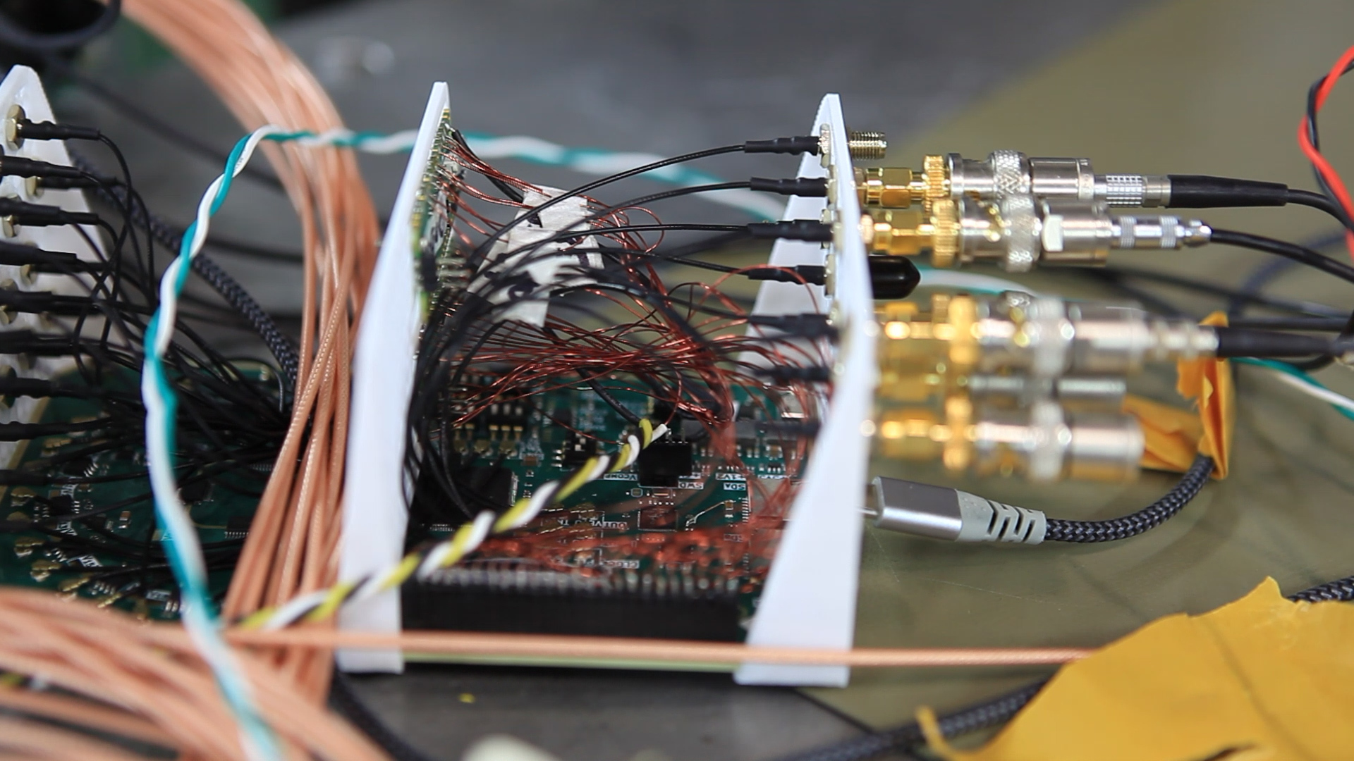
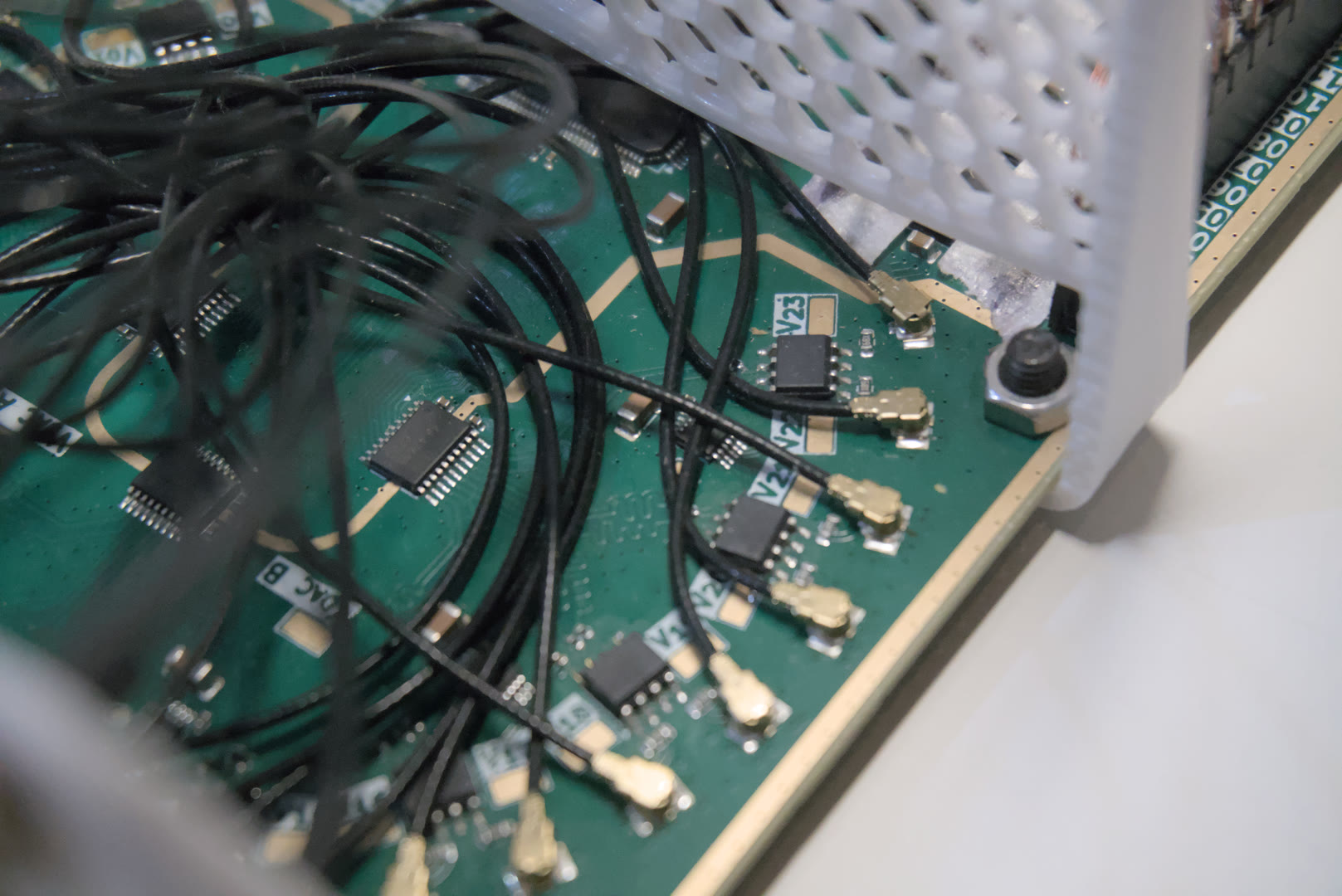
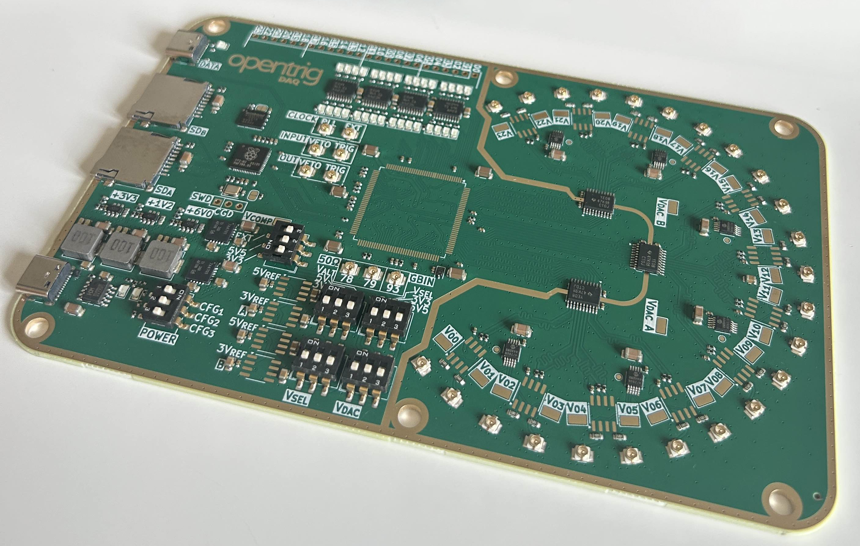
Frontend Frontend Frontend Bare PCB

License

This project is open-source under the Eclipse Public License - v 2.0.

Authors

Parts

438
QtyValueFootprintReferences
65100nCapacitor_SMD:C_0402_1005MetricC1, C11, C100, C101, C102, C103, C104, C105, C106, C107, C108, C109, C110, C111, C113, C114 +49
35LEDLED_SMD:LED_0805_2012MetricD1, D2, D11, D12, D13, D14, D15, D16, D17, D18, D19, D20, D21, D22, D23, D24 +19
33470RResistor_SMD:R_0402_1005MetricR10, R11, R12, R13, R14, R15, R16, R18, R58, R61, R62, R63, R64, R65, R66, R67 +17
33IPEX-1digital:BWIPX-1-001EJ1, J2, J3, J21, J22, J23, J24, J25, J26, J27, J28, J29, J30, J31, J32, J33 +17
27TestPoint_Altdigital:TestPoint_Keystone_5015_Micro_MiniTP10, TP12, TP13, TP15, TP17, TP19, TP20, TP21, TP22, TP24, TP26, TP28, TP29, TP30, TP32, TP33 +11
2410RResistor_SMD:R_0402_1005MetricR100, R105, R106, R109, R110, R111, R112, R113, R116, R121, R122, R123, R126, R127, R128, R129 +8
2449.9RResistor_SMD:R_0603_1608MetricR101, R102, R103, R104, R107, R108, R114, R115, R117, R118, R119, R120, R124, R125, R131, R132 +8
191uCapacitor_SMD:C_0805_2012MetricC10, C47, C48, C52, C53, C66, C67, C68, C70, C72, C75, C78, C82, C83, C87, C112 +3
19TestPointTestPoint:TestPoint_Pad_D1.0mmTP1, TP2, TP3, TP11, TP14, TP16, TP18, TP23, TP25, TP27, TP31, TP34, TP36, TP38, TP43, TP45 +3
140RResistor_SMD:R_0402_1005MetricR3, R4, R5, R6, R7, R8, R9, R19, R20, R33, R36, R69, R78, R88
1410uCapacitor_SMD:C_1206_3216MetricC35, C37, C42, C49, C50, C54, C60, C65, C76, C79, C84, C88, C91, C96
1310kResistor_SMD:R_0402_1005MetricR21, R28, R29, R30, R31, R32, R34, R35, R48, R51, R55, R56, R57
12TLV3502AIDRPackage_SO:SOIC-8_3.9x4.9mm_P1.27mmU25, U26, U27, U28, U30, U31, U32, U33, U35, U36, U37, U38
61kResistor_SMD:R_0402_1005MetricR24, R27, R37, R50, R52, R54
622uCapacitor_SMD:C_0603_1608MetricC45, C46, C57, C58, C63, C64
6M4MountingHole:MountingHole_4.3mm_M4_ISO14580_Pad_TopBottomH1, H2, H3, H4, H5, H6
6MCP4728Package_SO:MSOP-10_3x3mm_P0.5mmU15, U16, U18, U20, U21, U23
6SW_DIP_x03Button_Switch_SMD:SW_DIP_SPSTx03_Slide_6.7x9.18mm_W8.61mm_P2.54mm_LowProfileSW1, SW2, SW3, SW4, SW5, SW6
54.7uCapacitor_SMD:C_1206_3216MetricC2, C16, C18, C20, C23
474HC244Package_SO:TSSOP-20_4.4x6.5mm_P0.65mmU2, U11, U12, U13
4Conn_01x03_PinConnector_PinHeader_1.00mm:PinHeader_1x03_P1.00mm_Vertical_SMD_Pin1LeftJ10, J11, J13, J15
310uHInductor_SMD:L_Changjiang_FXL0630L1, L2, L3
347kResistor_SMD:R_0402_1005MetricR38, R40, R49
3TPS54302Package_TO_SOT_SMD:SOT-23-6U5, U8, U9
3TXB0108PWPackage_SO:TSSOP-20_4.4x6.5mm_P0.65mmU24, U29, U34
2100kResistor_SMD:R_0402_1005MetricR42, R46
2100kResistor_SMD:R_0603_1608MetricR39, R43
215pCapacitor_SMD:C_0402_1005MetricC39, C40
21u 25VCapacitor_SMD:C_0402_1005MetricC33, C34
222kResistor_SMD:R_0402_1005MetricR44, R53
227RResistor_SMD:R_0402_1005MetricR25, R26
233kResistor_SMD:R_0402_1005MetricR41, R45
24.7kResistor_SMD:R_0402_1005MetricR22, R23
247pCapacitor_SMD:C_0402_1005MetricC56, C62
249.9RResistor_SMD:R_0402_1005MetricR1, R2
25.1kResistor_SMD:R_0402_1005MetricR59, R60
2Micro_SD_Card_Det1digital:microSD_HC_MSD-4-AJ16, J18
2REF5030IDPackage_SO:SOIC-8_3.9x4.9mm_P1.27mmU14, U19
2REF5050IDPackage_SO:SOIC-8_3.9x4.9mm_P1.27mmU17, U22
2SolderJumper_2_OpenJumper:SolderJumper-2_P1.3mm_Open_RoundedPad1.0x1.5mmJP1, JP2
2TPS7A4701Package_DFN_QFN:Texas_RGW0020A_VQFN-20-1EP_5x5mm_P0.65mm_EP3.15x3.15mm_ThermalViasU6, U7
2USB_C_Receptacle_USB2.0_16PConnector_USB:USB_C_Receptacle_GCT_USB4105-xx-A_16P_TopMnt_HorizontalJ19, J20
1100RResistor_SMD:R_0402_1005MetricR17
1100pCapacitor_SMD:C_0402_1005MetricC44
112 MHz ABM8-272-T3Crystal:Crystal_SMD_Abracon_ABM8AIG-4Pin_3.2x2.5mmY1
11N4148WSDiode_SMD:D_SOD-323D7
1220kResistor_SMD:R_0603_1608MetricR47
1CH224KPackage_SO:SSOP-10-1EP_3.9x4.9mm_P1mm_EP2.1x3.3mmU10
1Conn_01x02_PinConnector_PinHeader_1.00mm:PinHeader_1x02_P1.00mm_Vertical_SMD_Pin1LeftJ14
1Conn_01x03_PinConnector_PinHeader_2.54mm:PinHeader_1x03_P2.54mm_VerticalJ17
1Conn_01x10_PinConnector_PinHeader_1.00mm:PinHeader_1x10_P1.00mm_Vertical_SMD_Pin1LeftJ12
1Conn_01x24_PinConnector_PinHeader_2.54mm:PinHeader_1x24_P2.54mm_VerticalJ45
1ESDA25P35digital:D_1610_4027MetricD10
1ICE40HX4K-TQ144Package_QFP:TQFP-144_20x20mm_P0.5mmU1
1LOGOlogos:hep_20mmG***
1LOGOlogos:opentrigG***
1LOGOlogos:sc_17mmG***
1RP2040Package_DFN_QFN:QFN-56-1EP_7x7mm_P0.4mm_EP3.2x3.2mmU4
1W25Q32JVZPPackage_SON:WSON-8-1EP_6x5mm_P1.27mm_EP3.4x4.3mmU3

Similar boards

  • 2 layers128.5 × 42 mmTrigger, the printed circuit board in 3D

    Trigger

    Dawson-HEP/scintillating_chamber

    Our proposal to the 2025 Beamline for schools competition. It consists of an arrangement of scitillator rods to detect and model the trajectory of cosmic ray in three dimensions.

    132 parts2EPL-2.0
  • 4 layers88 × 155 mmHACK CLUB RELATEDbackup, the printed circuit board in 3D

    HACK CLUB RELATEDbackup

    Studented0/universal-ai-terminal

    A pocketable AI terminal that runs Claude Code and Ollama over LTE. Custom carrier board for a Raspberry Pi Compute Module 5, 7" AMOLED touchscreen, and its own cellular modem so it doesn't need WiFi.

    104 parts1MIT
  • 2 layers100.5 × 95.8 mmADS1299-test circuit, the printed circuit board in 3D

    ADS1299-test circuit

    IIBM/EEG

    Circuito, PCB y data sobre el diseño de un dispositivo de adquisición de EEG. Florencia Grosso y Brian Santillán. IIBM FIUBA.

    109 parts
  • 2 layers65 × 78 mmBbb adc, the printed circuit board in 3D

    Bbb adc

    mattvenn/kicad

    The documentation for this workshop mostly consists of youtube screencasts. The screencasts are deliberately fast, if you need them slower then click the video's settings button and choose a slower speed.

    100 parts14
  • 4 layers35 × 42 mmADS7883-pmod, the printed circuit board in 3D

    ADS7883-pmod

    mattvenn/ADS7883-pmod

    pmod breakout for 2 x ADS7883 ADC

    31 parts4
  • 2 layers160 × 100 mmPIAD-18bits, the printed circuit board in 3D

    PIAD-18bits

    lnls-sirius/SPIxCONV

    This project consists of an 18-bit analog input (ADC) and output (DAC) within a range of 20 V (± 10 V) and 32 digital pins that can be either as inputs or outputs.

    178 parts1MIT
  • 2 layers156.2 × 141 mmMCU MotherBoard, the printed circuit board in 3D

    MCU MotherBoard

    bc-kim/PCB_KiCAD

    Tips Footprint of the resisotor and capacitor should be assigned aforetime because assigning those are comfusing when lots of reisistor and capacitors are used. 3. Reference: https://wikidocs.net/103412

    49 parts
  • 2 layers40.6 × 23 mmECG, the printed circuit board in 3D

    ECG

    IIBM/stethoscope

    28 parts

Questions

How big is the Digital PCB?

It measures 162.2 × 100 mm and has 4 copper layers, 1.6 mm thick.

What parts does the Digital use?

438 parts, built around the ICE40HX4K-TQ144, RP2040, 74HC244D and MCP4728-E/UN. The full list of its parts is on this page, with links to each part's symbol and footprint where PCBKit's library has them.

Where can I download the Digital KiCad files?

From the Dawson-HEP/opentrig repository on GitHub, at the commit this page was made from: the board is hardware/digital.kicad_pcb and its schematic hardware/comparators.kicad_sch. PCBKit opens the board in the browser, with nothing to install.

Can I use the Digital design in my own project?

Its repository publishes it under the EPL-2.0 licence: you may reuse it on that licence's terms (keep the author's notice, and for a copyleft licence share your changes alike).