2 layers195.7 × 100 mm
PIAD-18bits
lnls-sirius/SPIxCONV
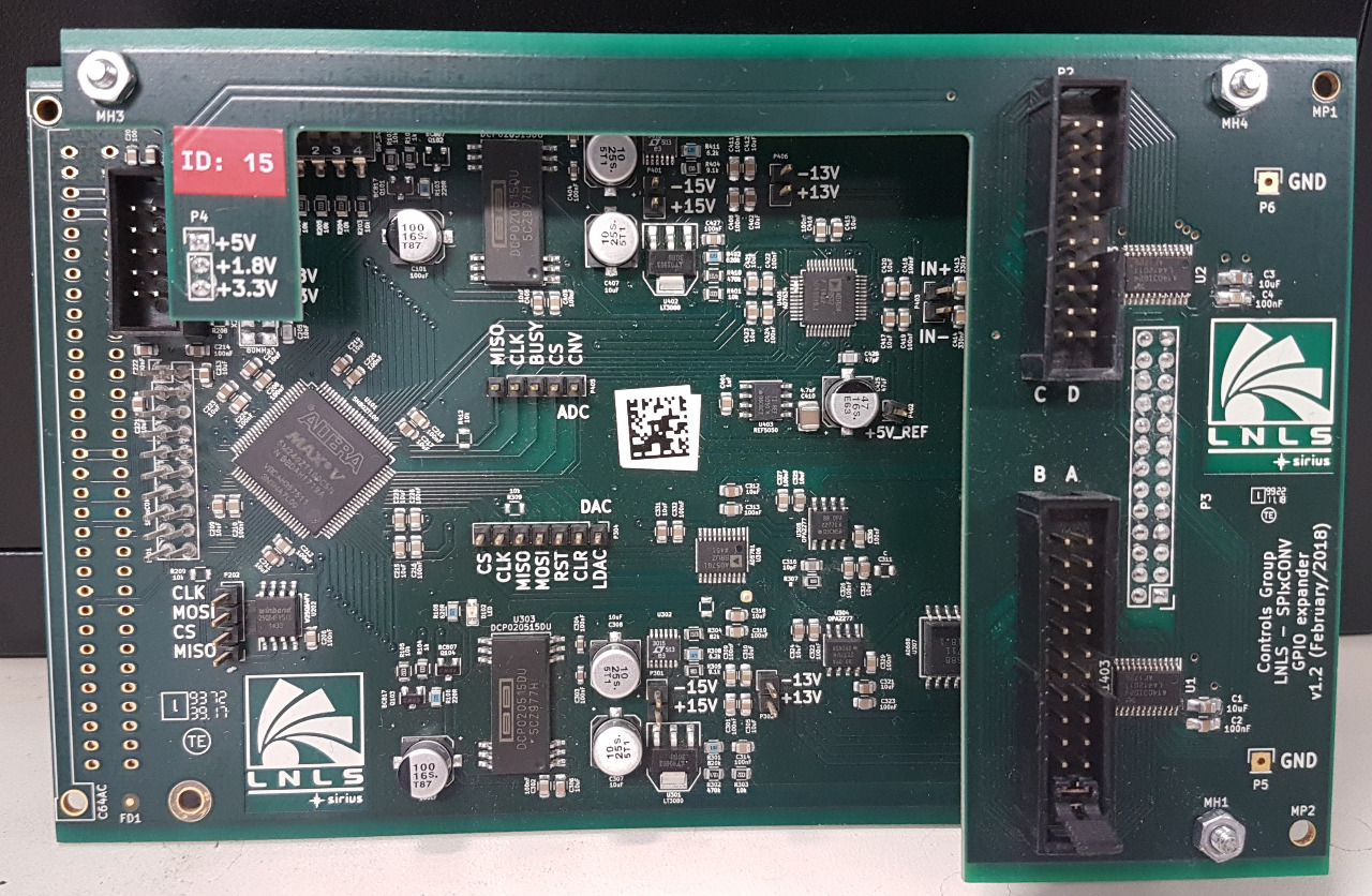
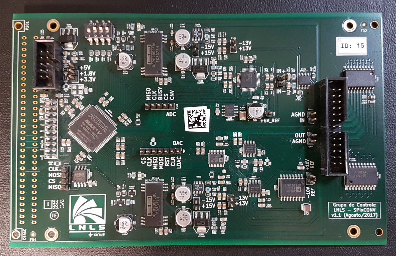
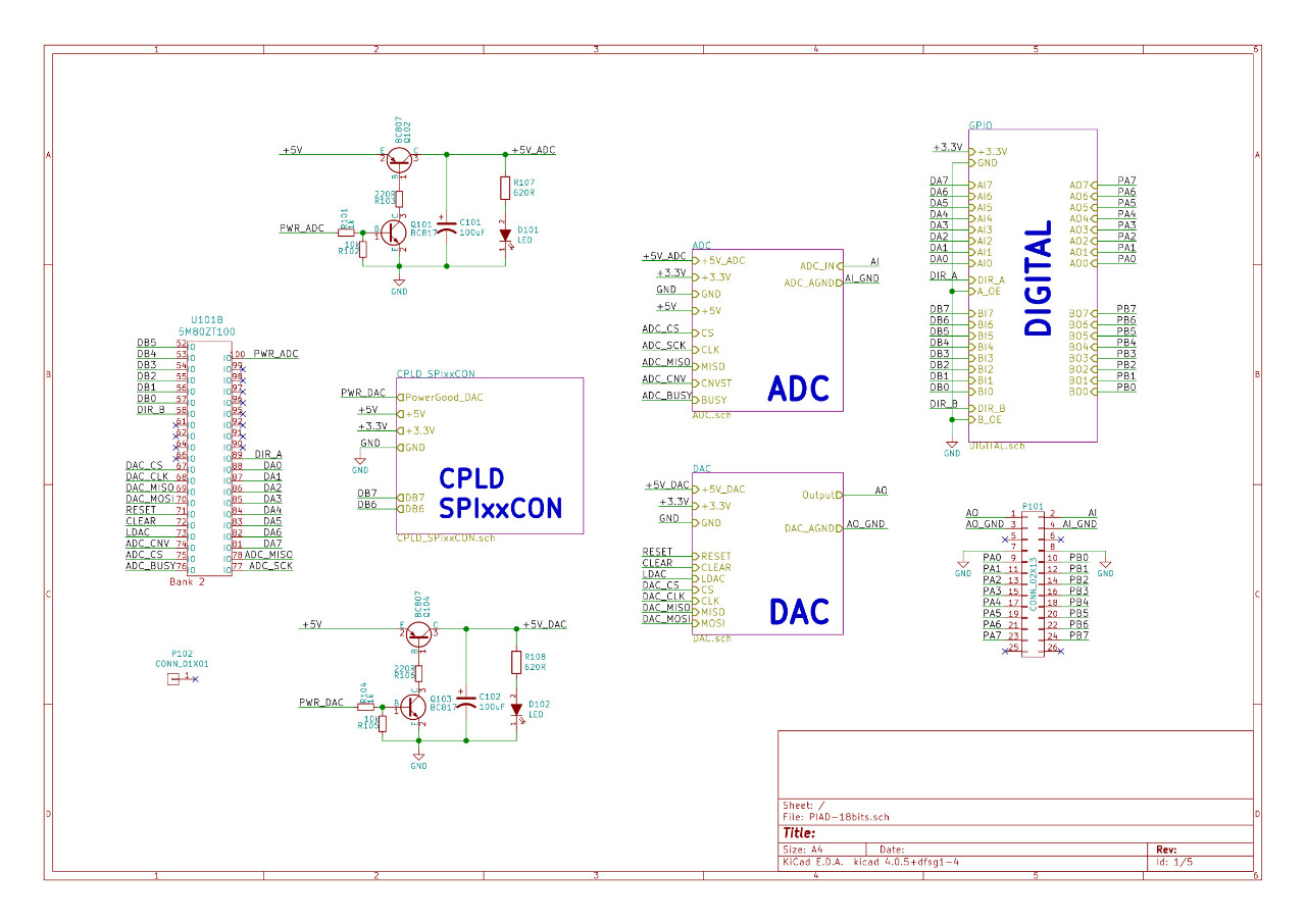
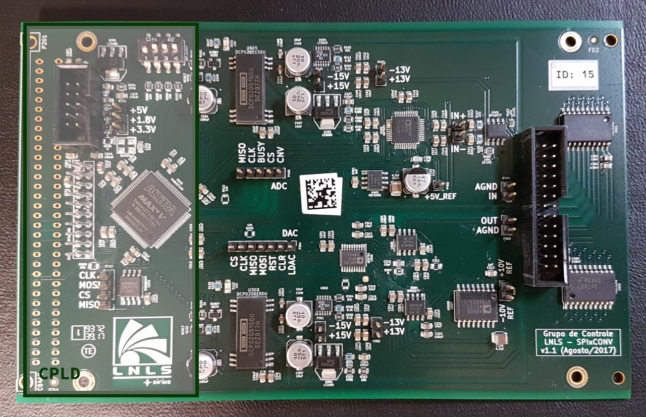
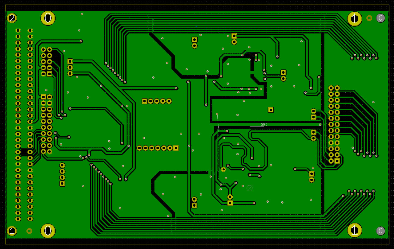
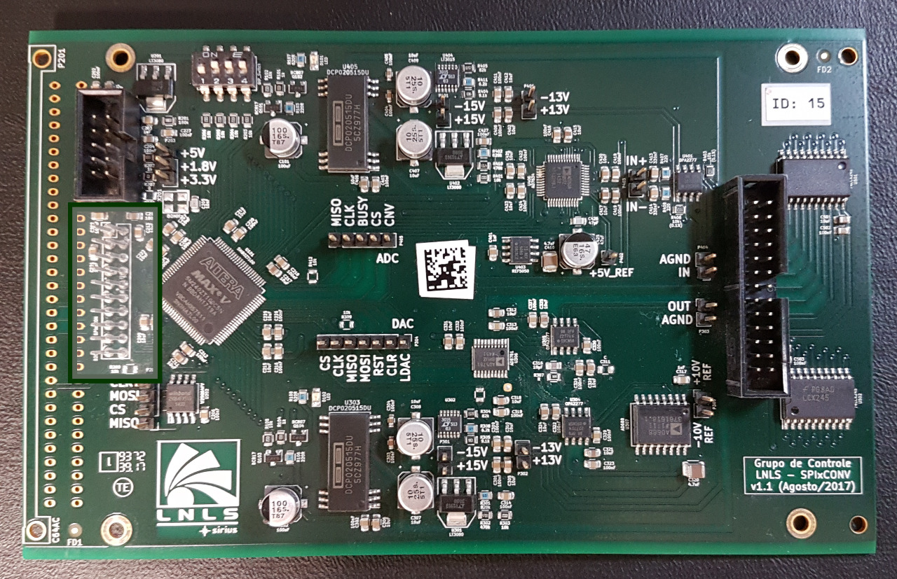
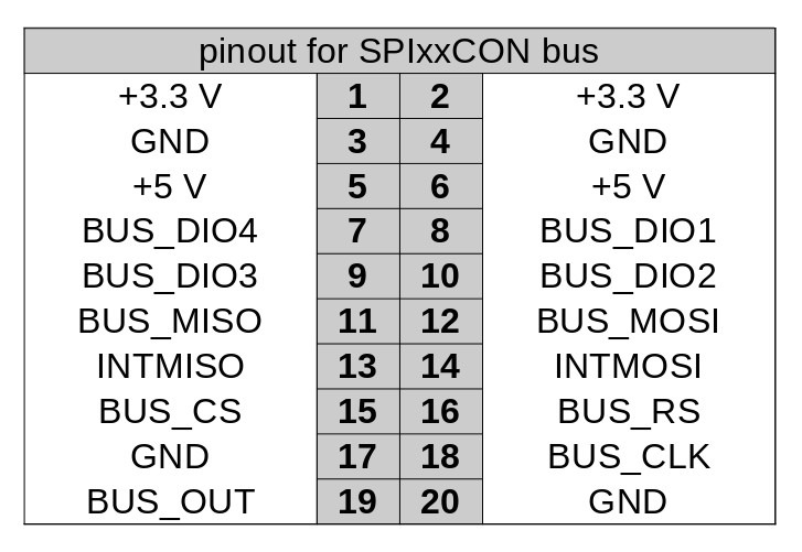
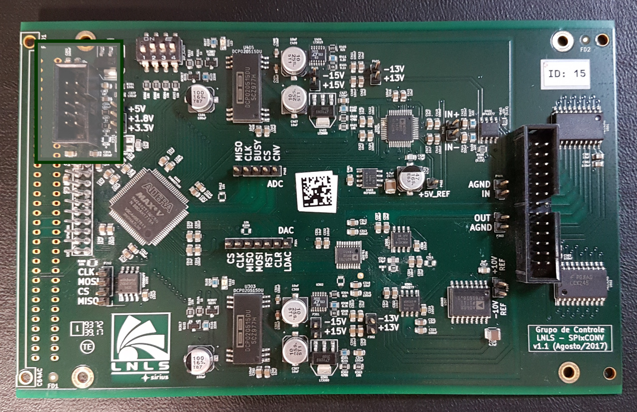
This project consists of an 18-bit analog input (ADC) and output (DAC) within a range of 20 V (± 10 V) and 32 digital pins that can be either as inputs or outputs.
36 parts1MIT

 lnls-sirius/SPIxCONV1
This project consists of an 18-bit analog input (ADC) and output (DAC) within a range of 20 V (± 10 V) and 32 digital pins that can be either as inputs or outputs.
PIAD-18bits is an open-source printed circuit board by lnls-sirius, from the lnls-sirius/SPIxCONV repository on GitHub, published under the MIT licence. It is a 2-layer board of 160 × 100 mm with 178 parts on 130 nets, routed with 1,886 tracks and 157 vias.
It is built around the 5M80ZT100A5N, DCP020515DU and LT3080EDD, with the OPA2277U, 74LCX245M and LT3015EQ among its other parts. Its parts include 91 capacitors, 38 resistors, 18 ICs, 17 connectors and 4 transistors.


This project consists of an 18-bit analog input (ADC) and output (DAC) within a range of 20 V (± 10 V) and 32 digital pins that can be either as inputs or outputs. This system interfaces with pulsed power electronics hardware in order to control the output voltage for pulsed magnets as well as read and write status commands to their power supplies. An operator interface (OPI) software based on Qt was also developed for remote control.
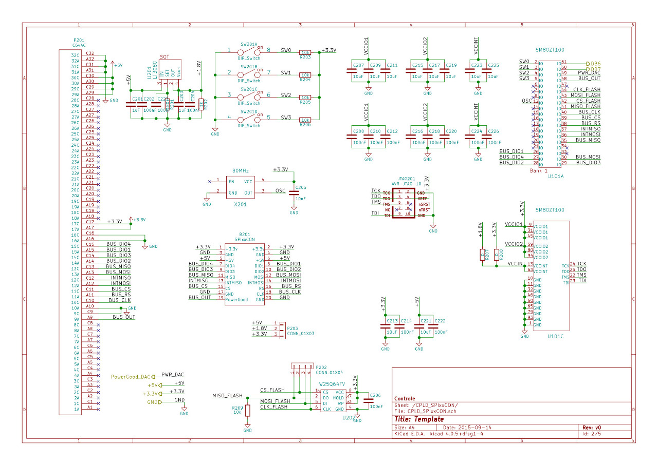
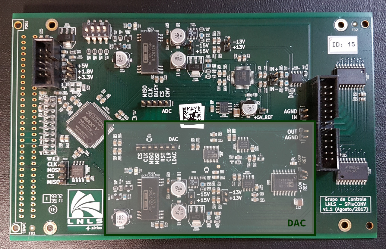
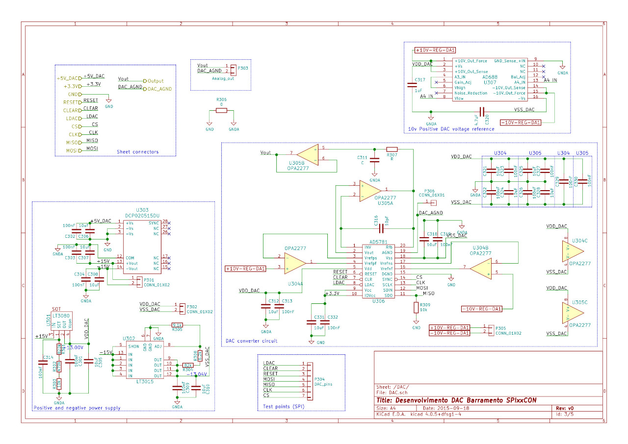
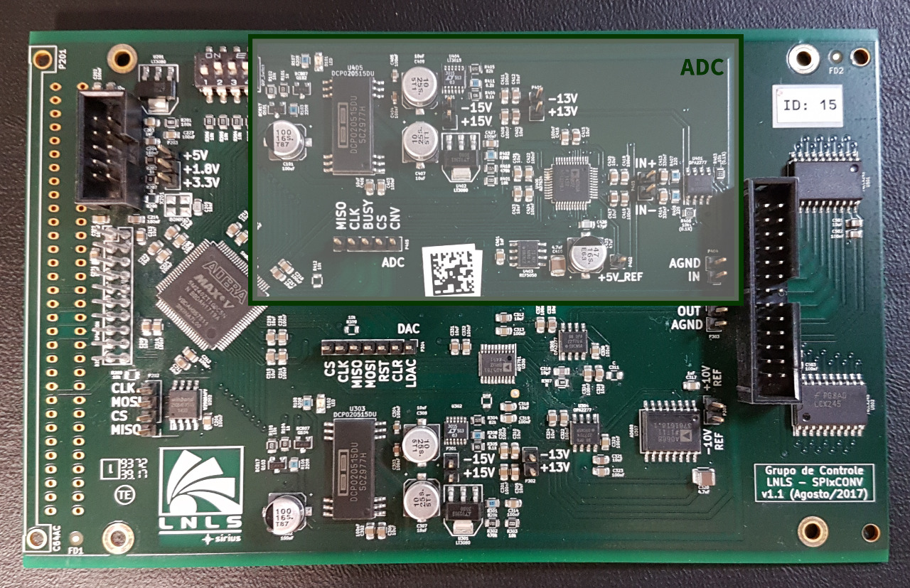
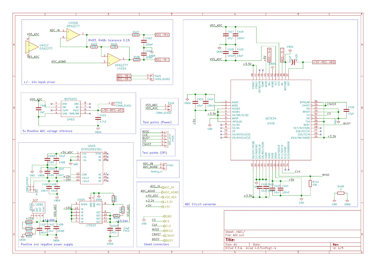
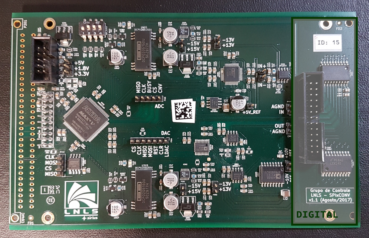
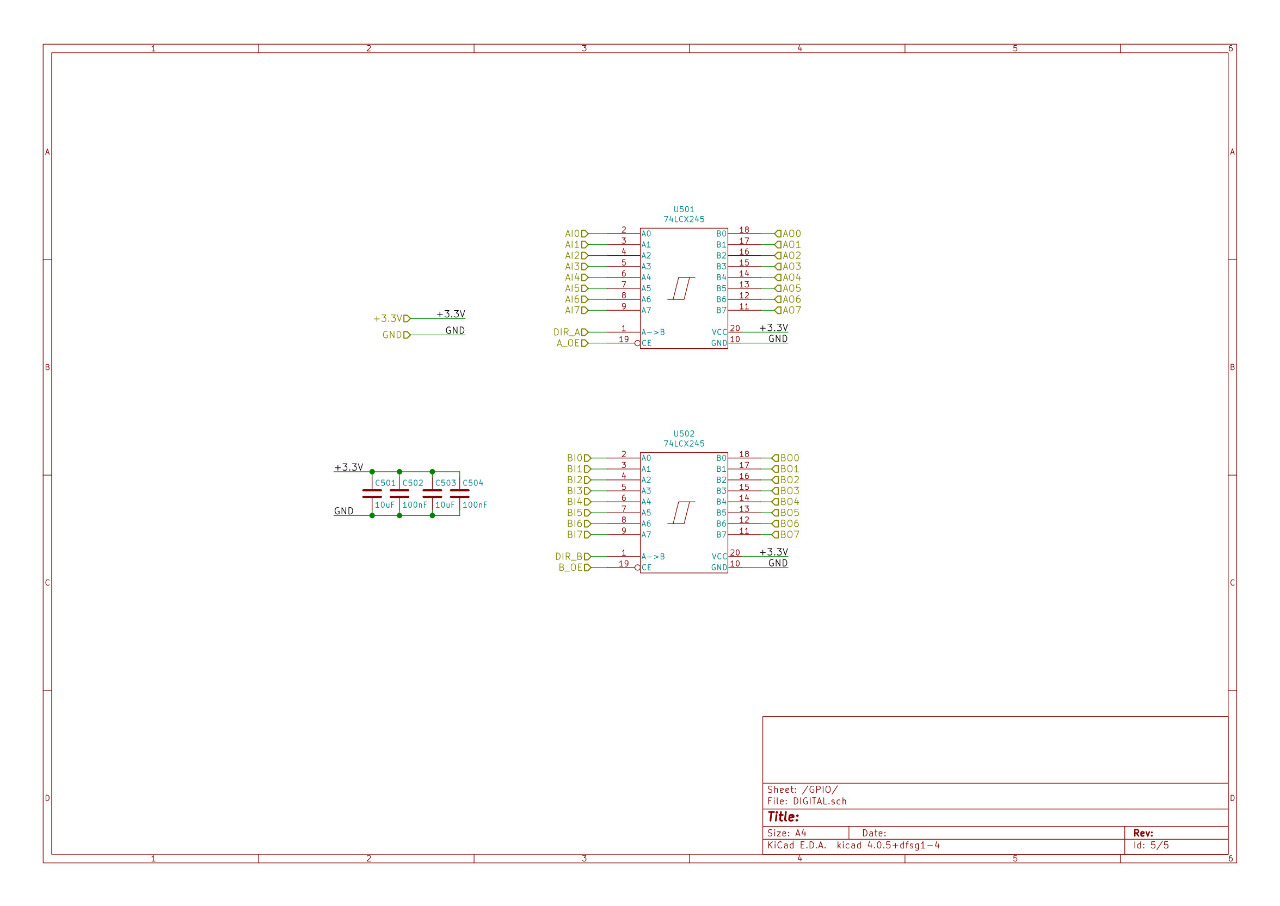
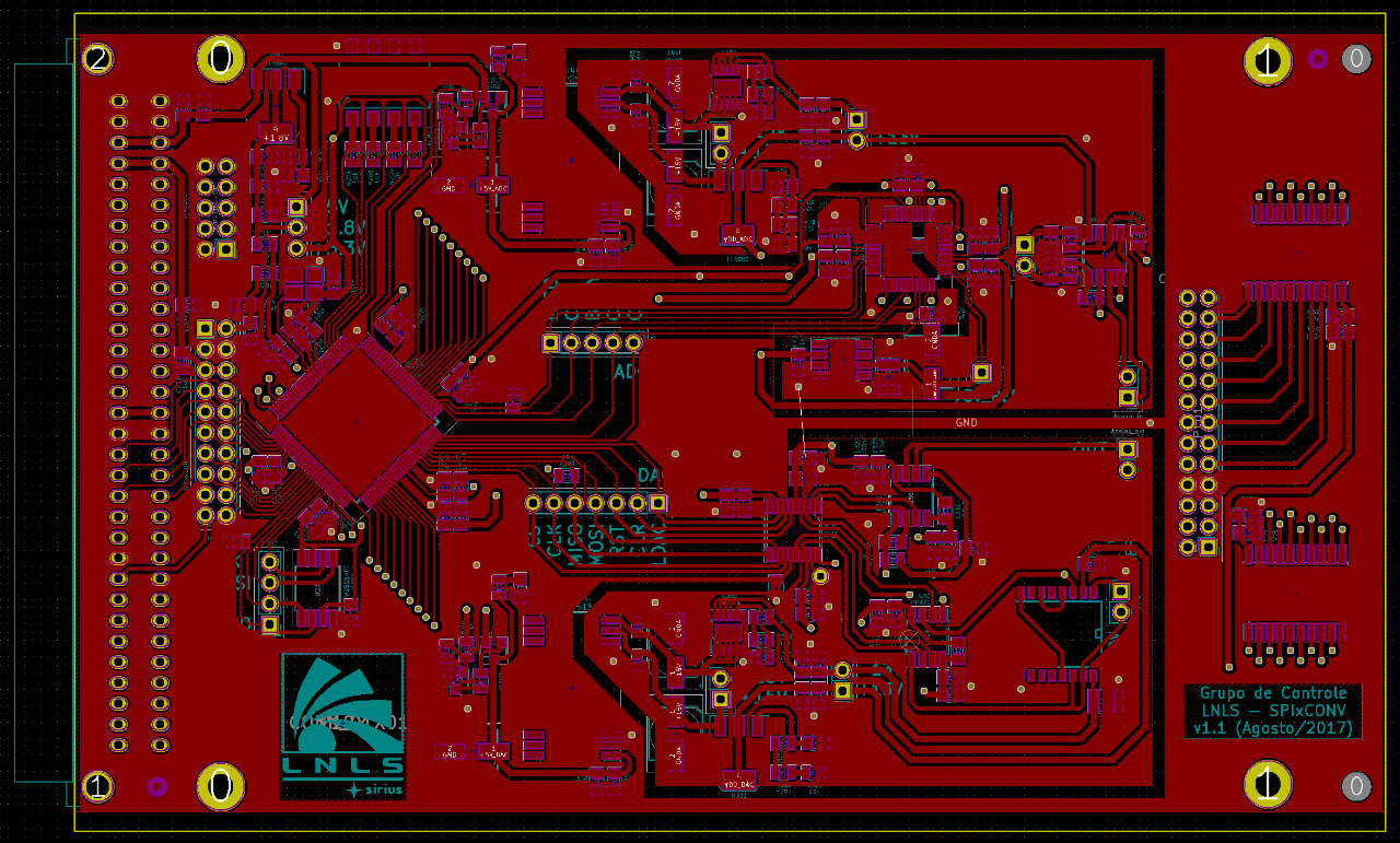
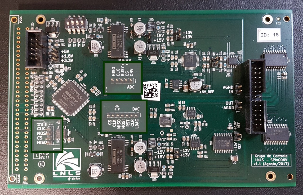
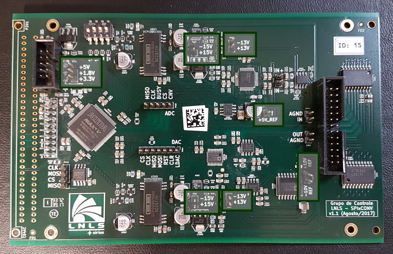
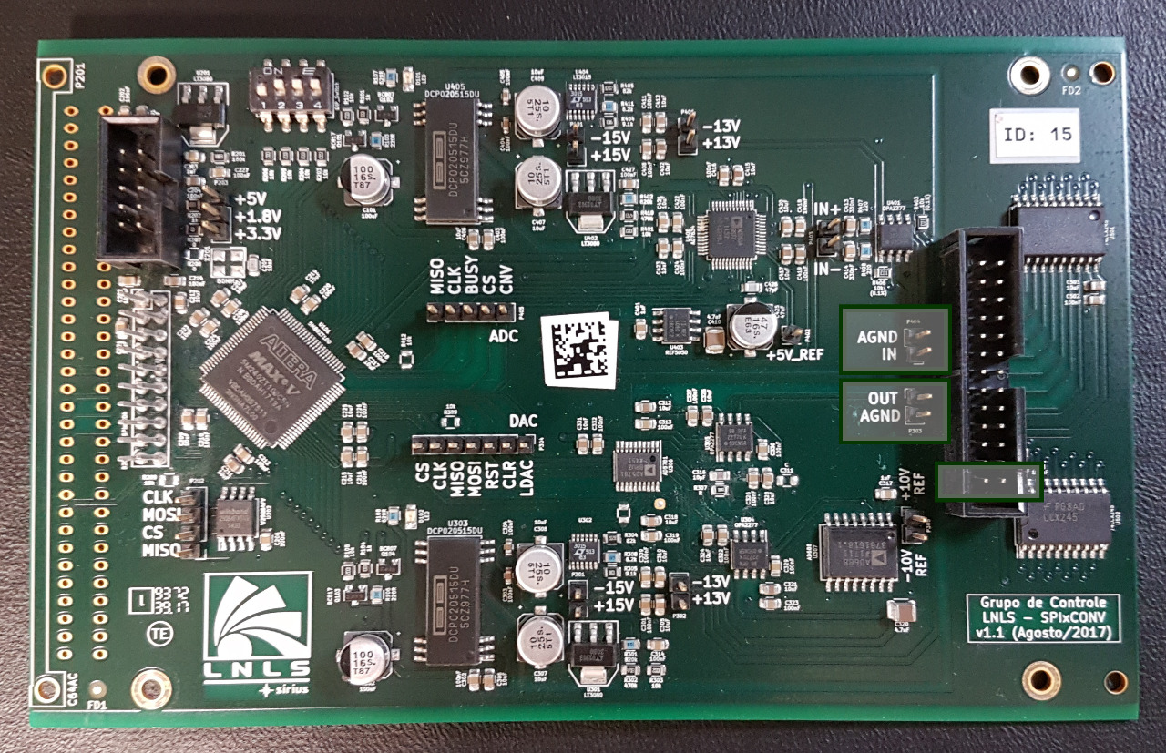
Bill of materials
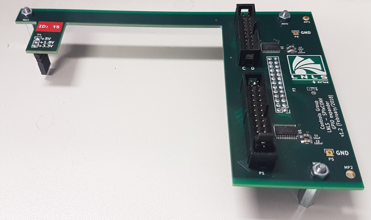
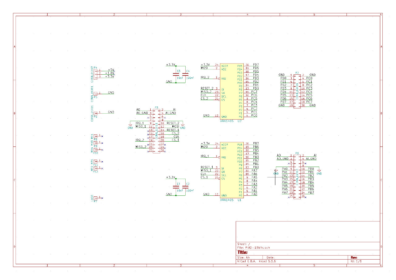
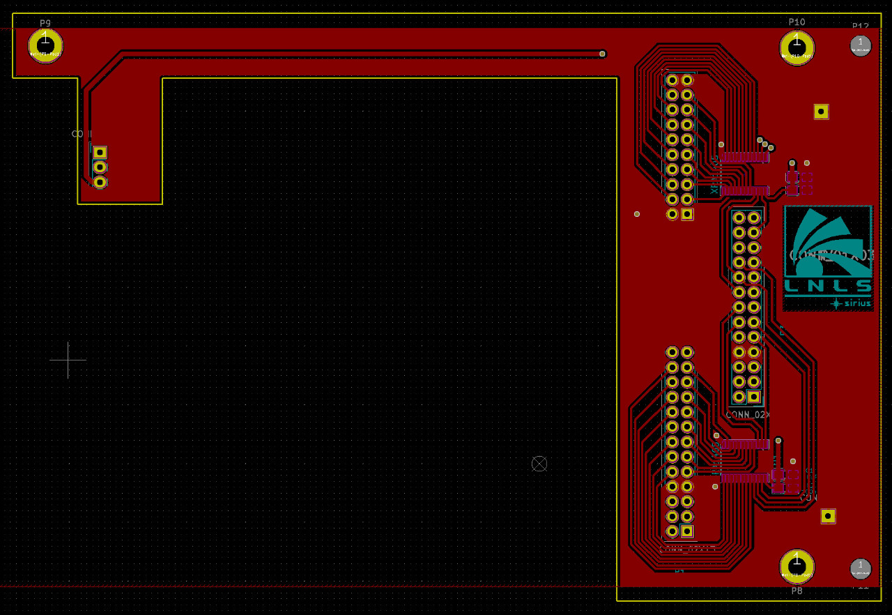
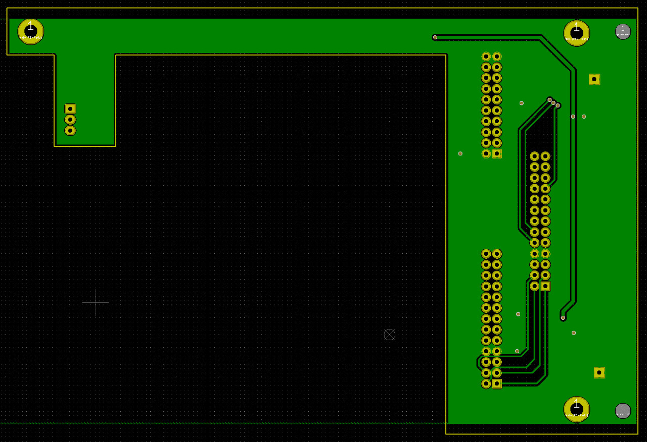
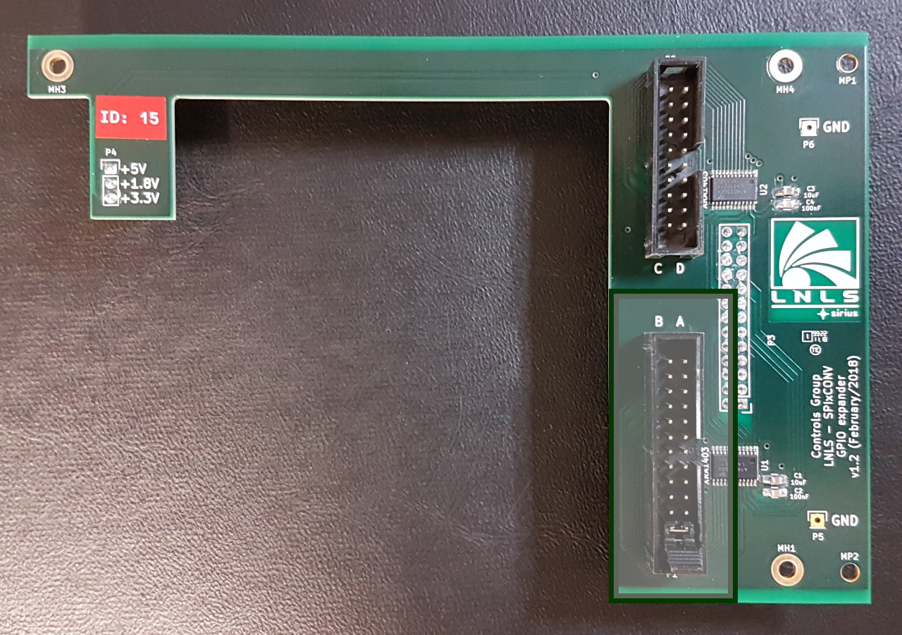
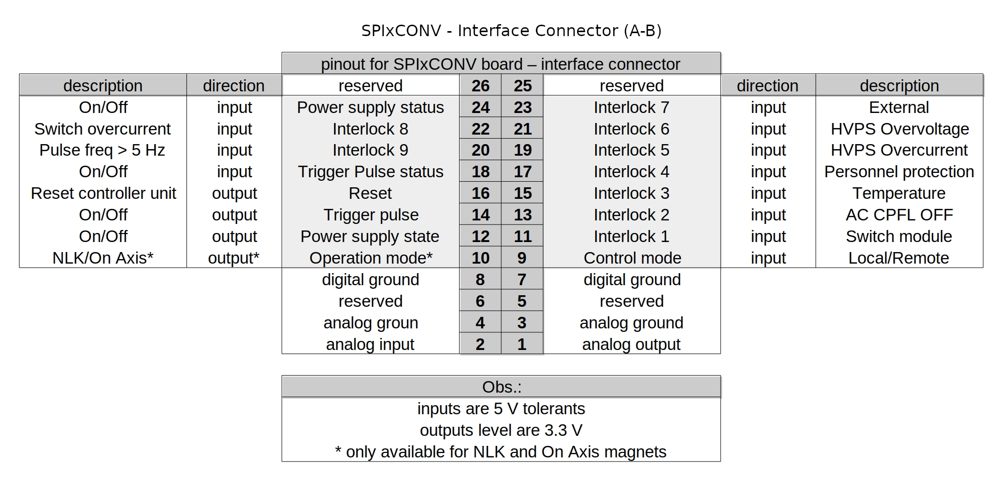
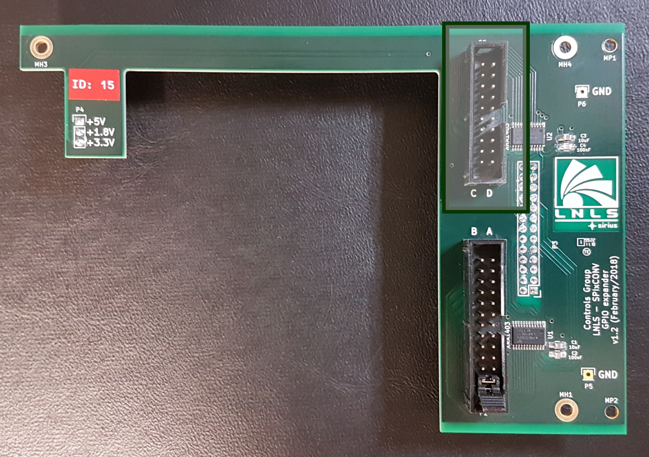
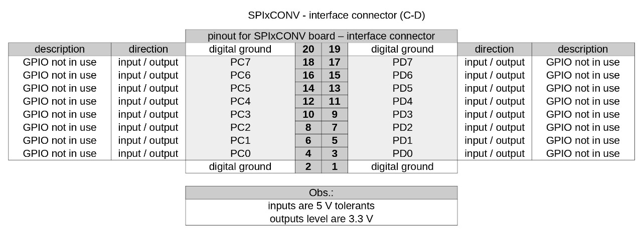
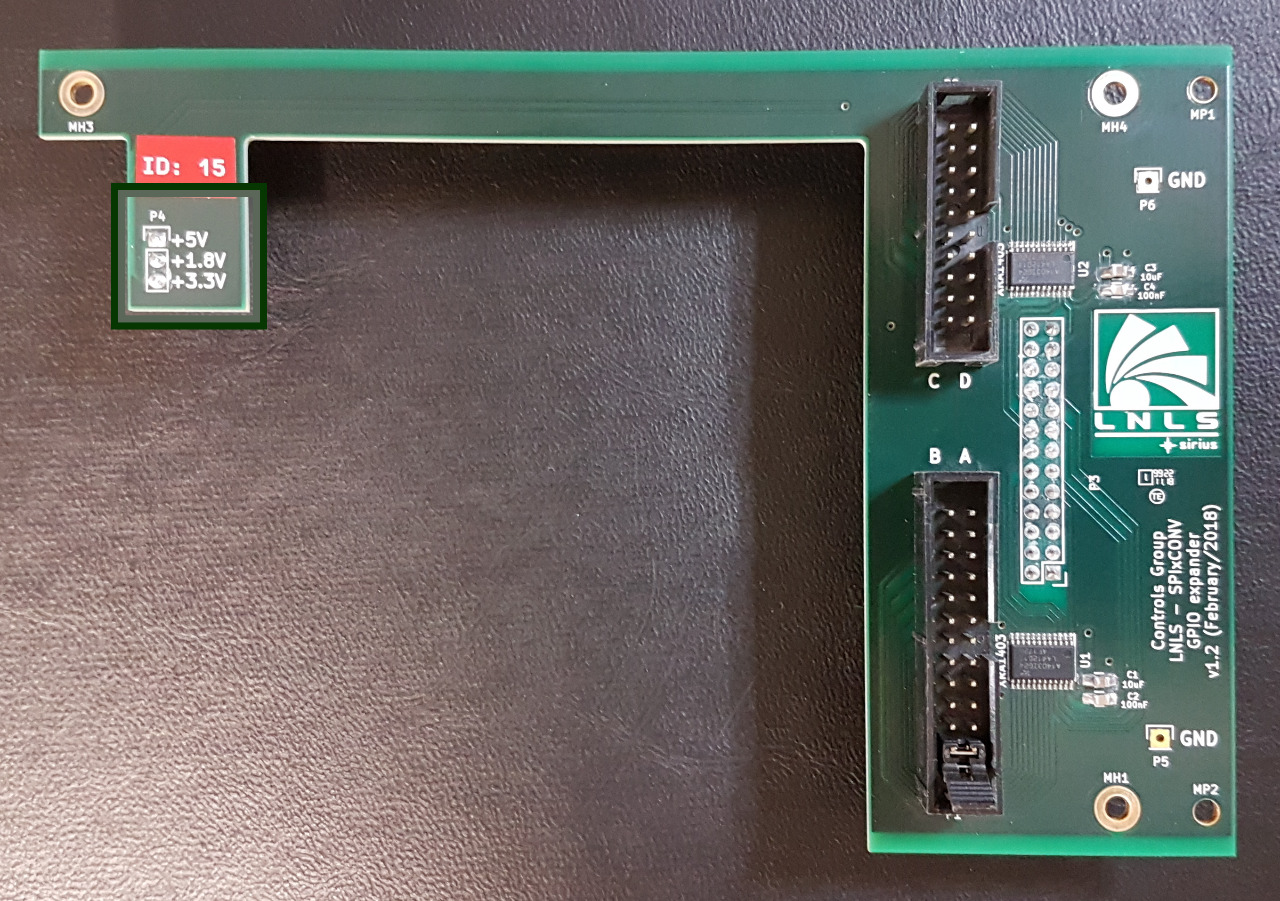
Bill of materials
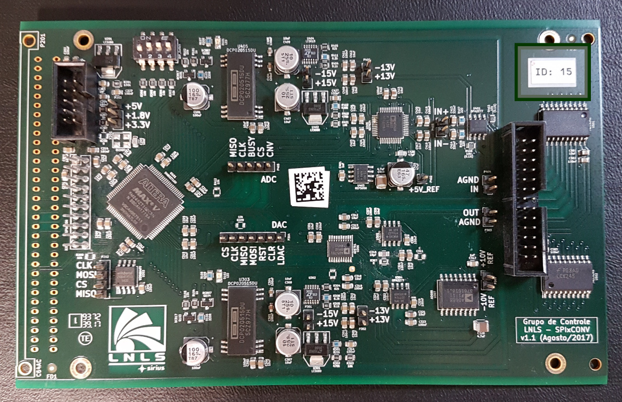
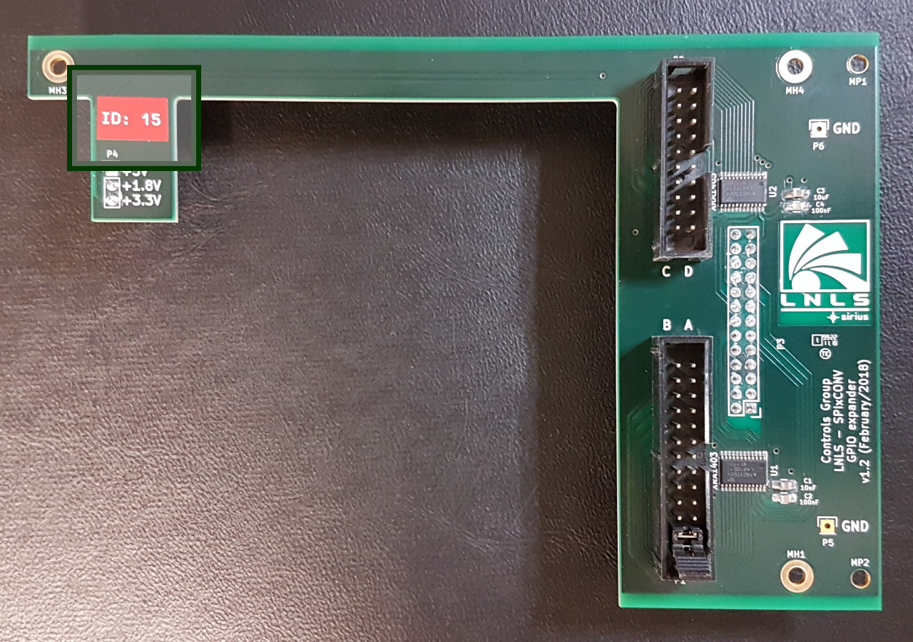
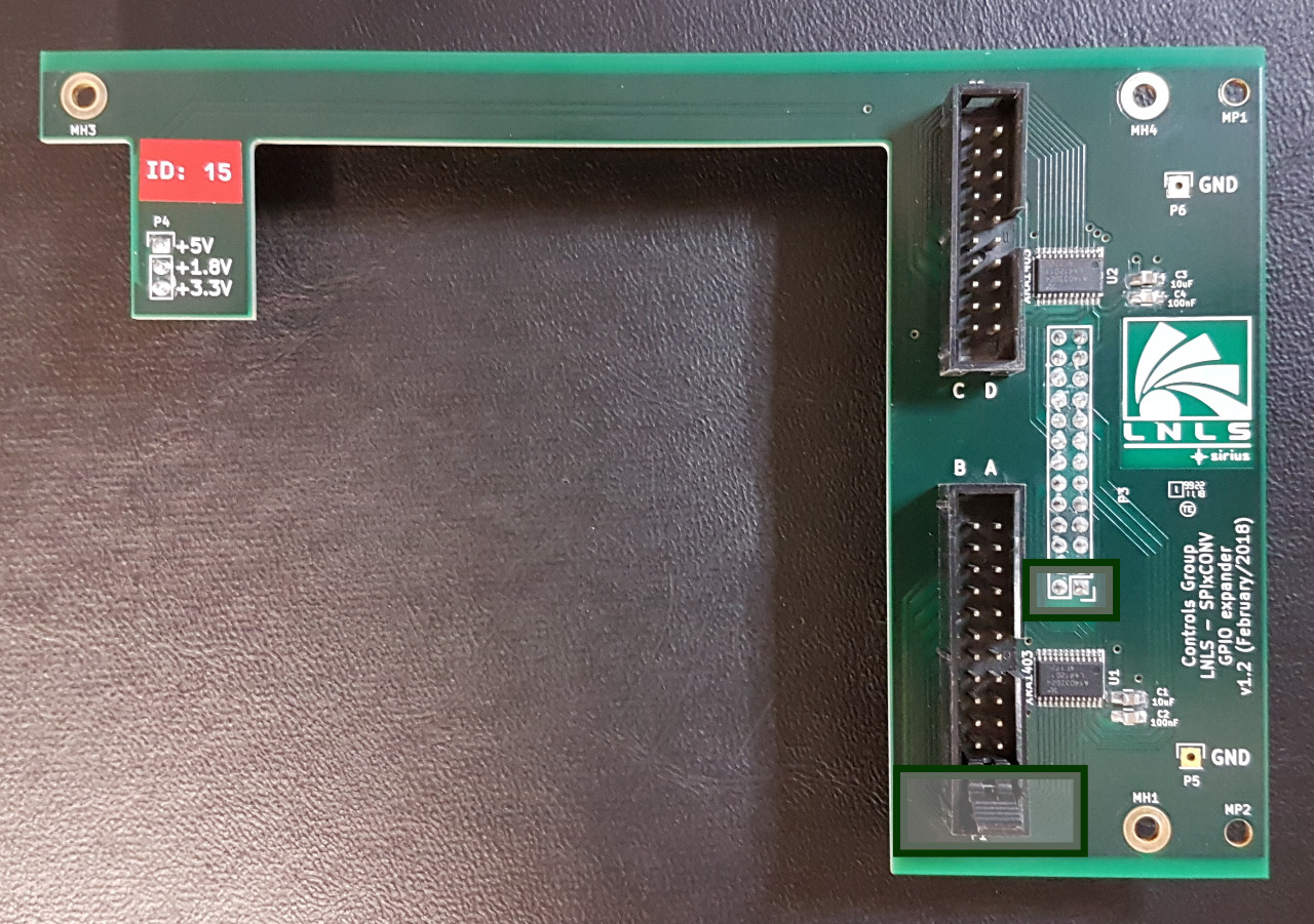
The software files of this project related to the server-side (IOC) is now available at streamdevice-ioc GitHub's repository under the "spixconv" directory.
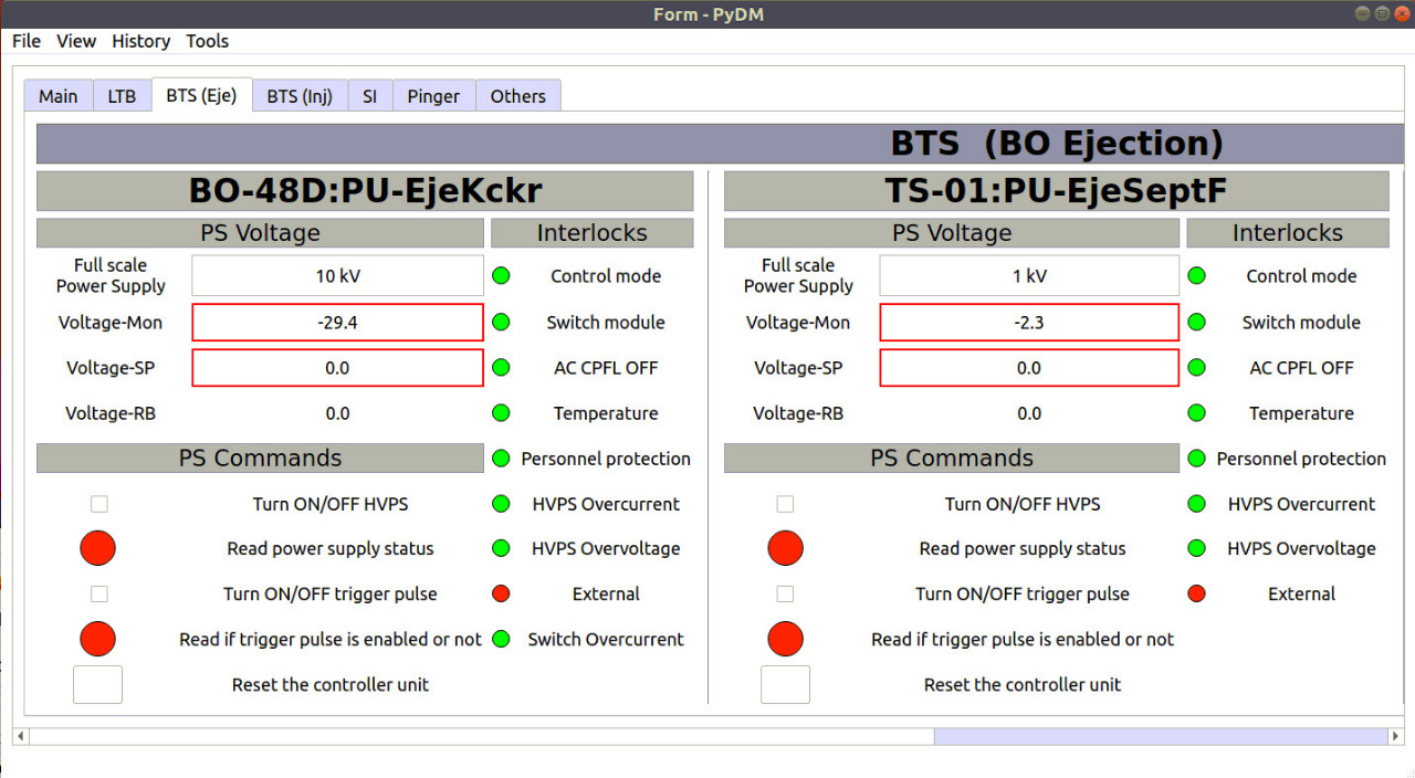
The software files related to the OPI (Operator Interface) is now at pydm-opi GitHub's repository.
Finally, the client-side (Python code) is at this repository under the scripts directory.
To remotely control the board an EPICS IOC with an OPI was developed.
The IOC was built using asynDriver and StreamDevice on top of it. The application is launched in a form of a Docker container. The Docker image can be found at Docker Hub with the tag "SPIxCONV" followed by the version (eg: SPIxCONV-v1.9.6).
To configure the parameters of the IOC a spreadsheet is used (available for CNPEM accounts only). PV's prefix, Power Supply voltage, host IP to connect to, scan rate and other settings can be adjusted.
Previously, Control System Studio was used to develop the OPI. The windows can still be found under the CSS directory. Lately, we have been using PyDM (Python Display Manager) to develop the windows. As stated before, the files related to the PyDM OPI is located in pydm-opi repository.
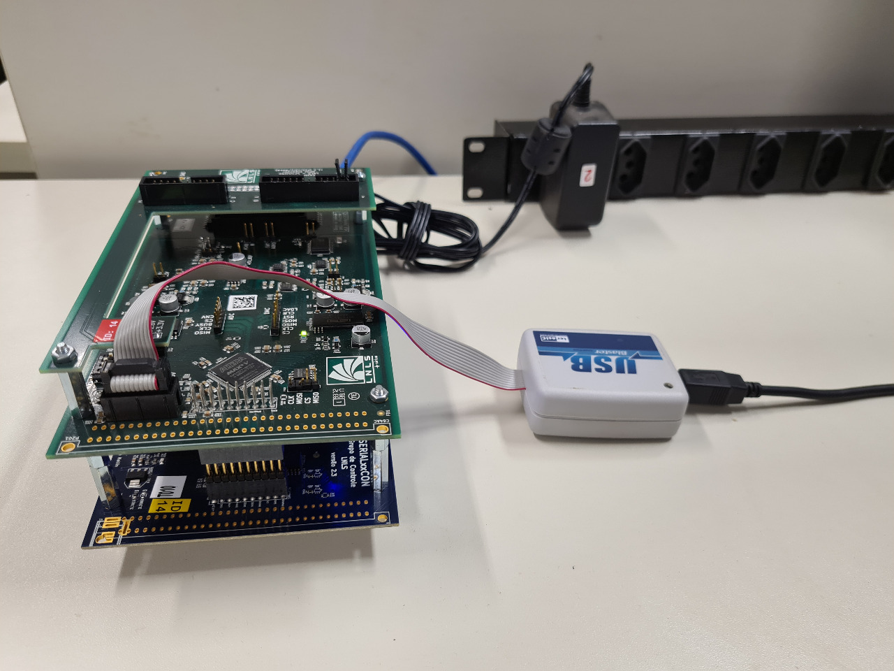
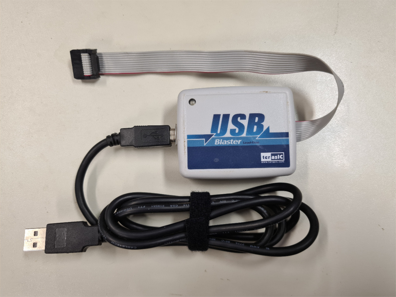
To achieve more confiability, a calibration is done considering the DAC adjusts and the ADC measures. The next figures show the setup for this procedure. We basically connect the DAC output to the voltmeter and to the ADC input simultaneously.
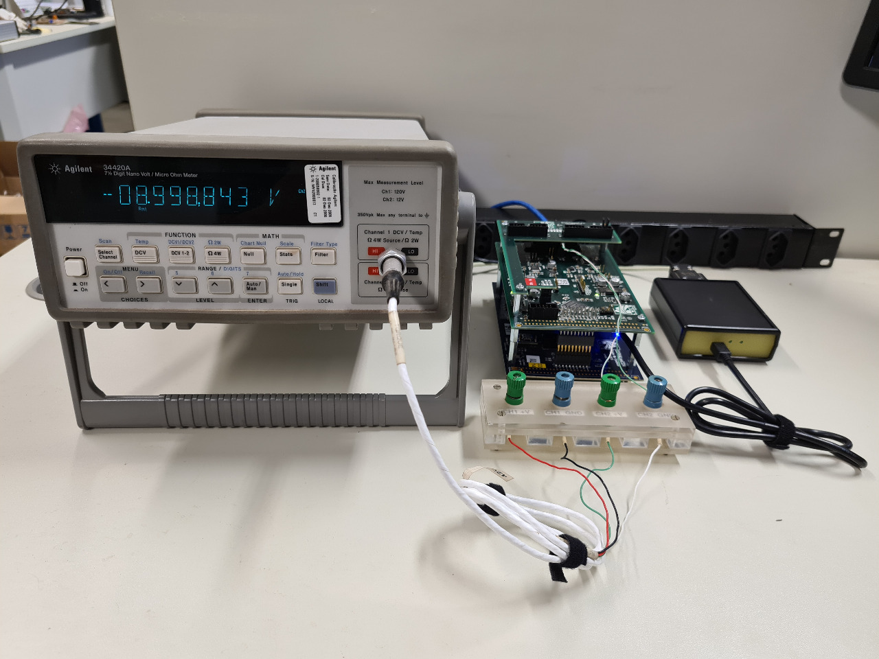
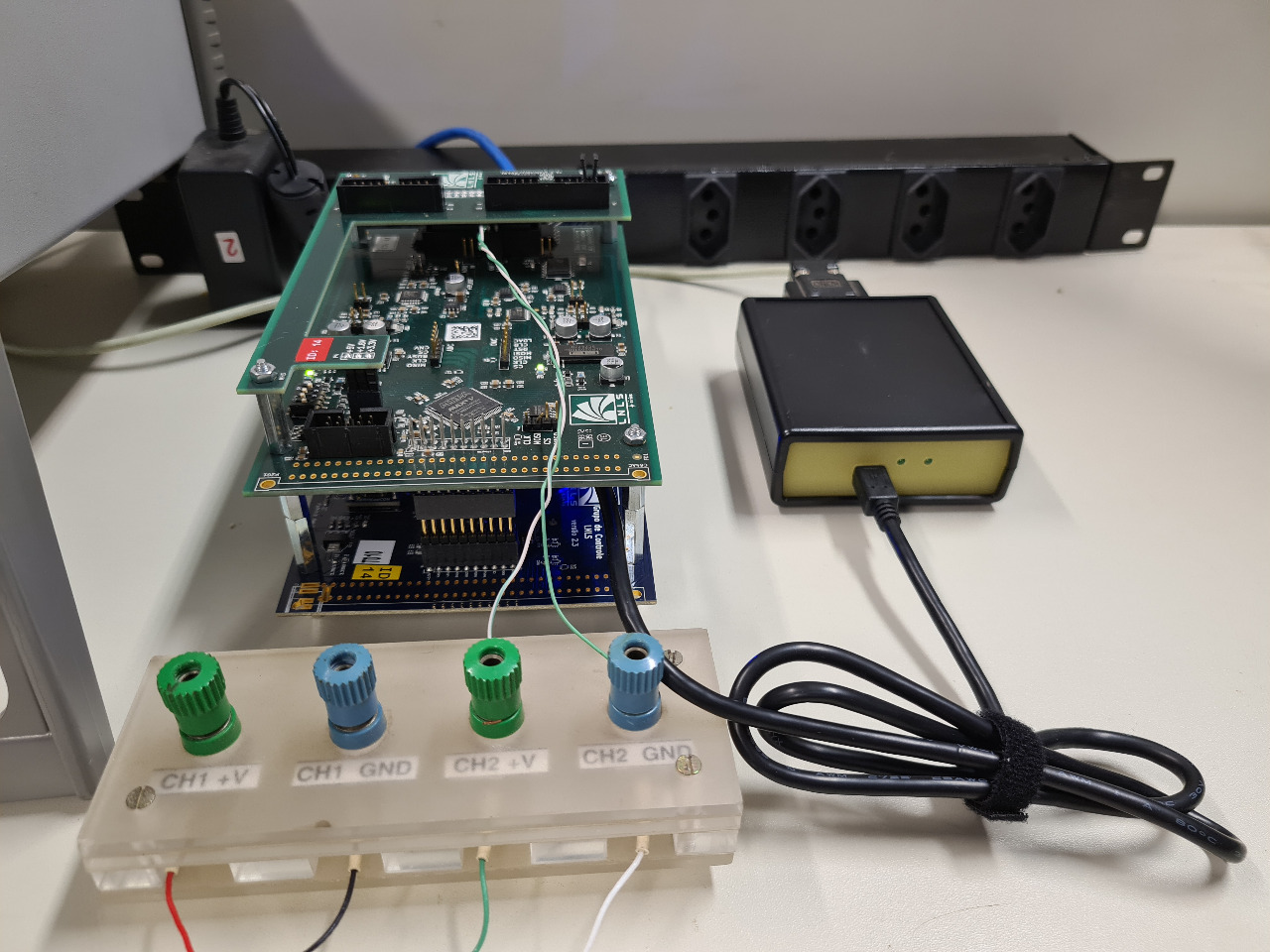
DAC calibration: To calibrate the DAC we set its output to -9 V and later to +9 V and measure the real output voltage with the help of a 7 ½ digit voltmeter (here we are using the Keysight 34420A. We then use both measures to calculate the angular and linear coeffients for this curve.
ADC calibration: Now that we have the DAC calibrated, we will use its output to calibrate the ADC coefficients. Again, we set the DAC output to -9 V (already considering the corrections), wait 60 s for thermal stabilization and read the voltage with the ADC. We then repeat the procedure for an adjustment of +9 V on the DAC output. Finally, these measures are used to calculate an angular and linear coefficient for the ADC.
An automated script was developed for this process. To control the voltmeter 34420A remotely we need a RS-232/USB adaptor to plug it in the USB connector of the BeagleBone Black. An important thing to note, is that the serial cable (RS-232) has an identification to show which side is the voltmeter's one and which should be connected to the adaptor.
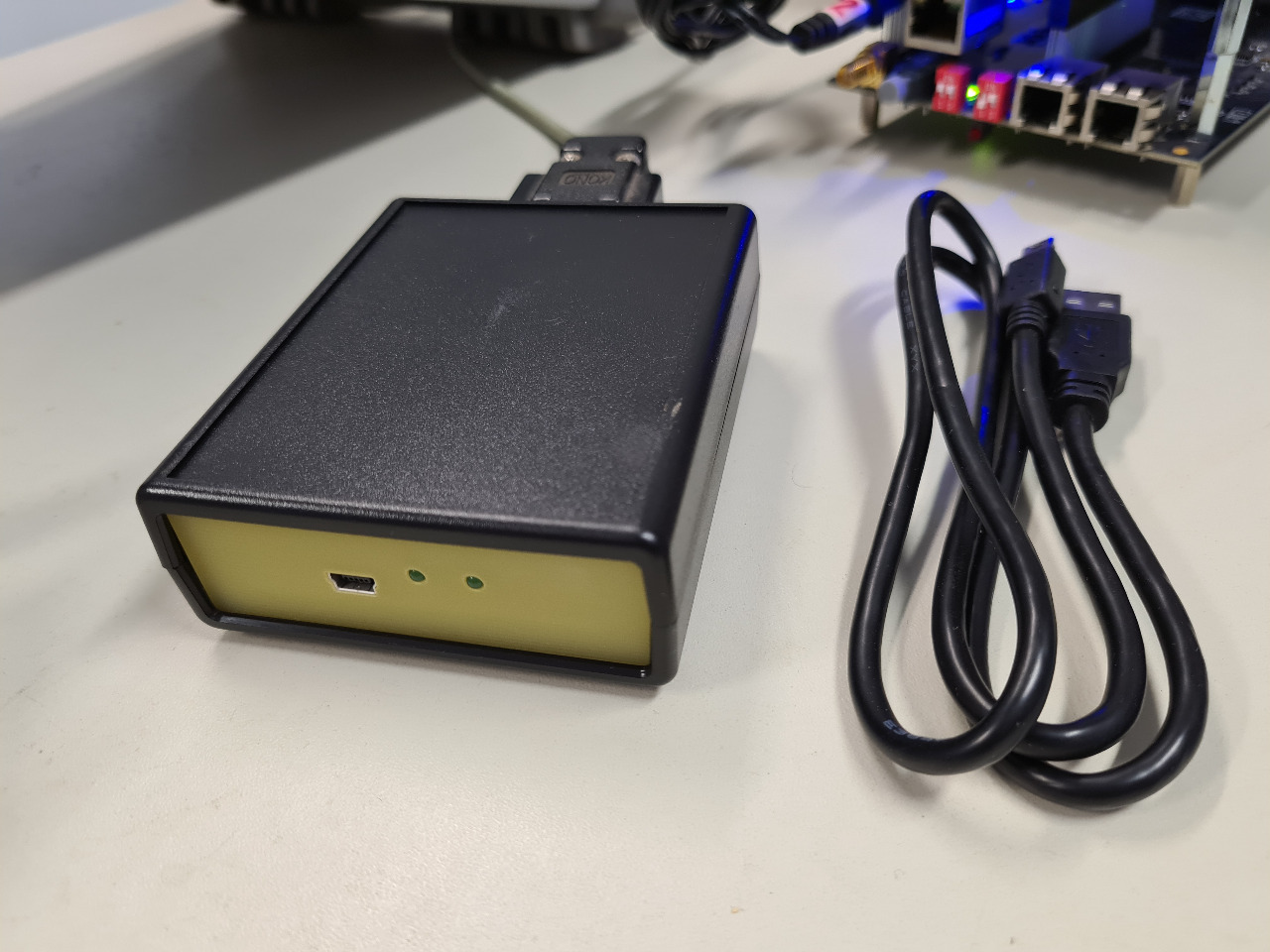
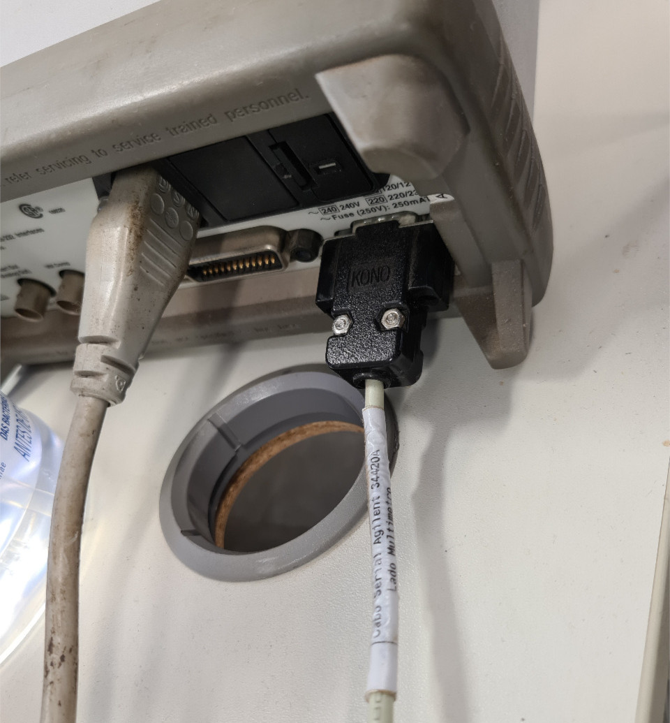
Finally, to calibrate the board, just connect to the BeagleBone Black and run the appropriate scrips, as showed below:
$ ssh root@<BBB-IP>
root@beaglebone:~# systemctl stop bbb-function
root@beaglebone:~# /root/spixconv/software/scripts/calibration.py <BOARD-ID>
    gain = 1.00014284735
    offset = -15.81235112
    gain = 1.00052568324
    offset = -66.6829873034
Where is the BeagleBone IP (for example "192.168.7.2") and the is the identification of the board (for example "15").
| Board ID | DAC gain | DAC offset | ADC gain | ADC offset | Date |
|---|---|---|---|---|---|
| 1 | 1.00022856796 | -23.604551795 | 1.00031151483 | -25.5034979525 | 06/14/2018 |
| 2 | 1.00026576963 | -28.880179670 | 1.00047415222 | -60.2158137830 | 06/14/2018 |
| 3 | 1.00030796599 | -32.699603180 | 1.00041814300 | -47.9227113769 | 06/18/2018 |
| 4 | 1.00017479634 | -17.242341185 | 1.00026390485 | -31.6174014794 | 06/19/2018 |
| 5 | 1.00017265115 | -13.974728690 | 1.00045784906 | -39.5533800101 | 06/19/2018 |
| 6 | 1.00015184443 | -11.674423865 | 1.00060158655 | -59.1729212883 | 06/19/2018 |
| 7 | 1.00019784934 | -20.918896760 | 1.00029330340 | -24.4439584471 | 06/19/2018 |
| 8 | 1.00035674834 | -37.769448800 | 1.00029168671 | -34.0324363824 | 06/19/2018 |
| 9 | 1.00023135812 | -26.566767695 | 1.00045023944 | -44.5911926966 | 06/19/2018 |
| 10 | 1.00020592482 | -21.571632830 | 1.00044201352 | -51.3525871959 | 06/19/2018 |
| 11 | 1.00014897135 | -16.862233835 | 1.00067934214 | -81.2456900362 | 06/19/2018 |
| 12 | 1.00022598345 | -22.008100925 | 1.00057691743 | -66.0110325831 | 06/19/2018 |
| 13 | 1.00032333122 | -33.267142775 | 1.00039023957 | -45.3552208747 | 06/19/2018 |
| 14 | 1.00016016368 | -18.311884625 | 1.00048566801 | -60.5575726483 | 06/19/2018 |
| 15 | 1.00022607238 | -22.051354520 | 1.00046470661 | -58.5770907625 | 06/19/2018 |
| 16 | 1.00028974958 | -32.626203140 | 1.00073037347 | -97.7370251289 | 06/19/2018 |
| 17 | 1.00027075563 | -27.292903805 | 1.00037276504 | -34.2682222150 | 06/20/2018 |
| 18 | 1.00017256223 | -15.753368945 | 1.00046720927 | -66.4461854942 | 06/20/2018 |
| 19 | 1.00023103020 | -24.296609315 | 1.00032961706 | -28.7417520711 | 06/20/2018 |
| 20 | 1.00019010191 | -20.998850375 | 1.00012983616 | -2.10309904365 | 06/20/2018 |
https://lnls-sirius.github.io/SPIxCONV/
Not connecting to IOC after BBB reboots:
Status: both nodes (IOC and BBB) show they are connected, but the IOC does not respond.
Solution: reboot IOC.
Flash memory loses data: Status: this happened once in three years. After a power cycle, the flash suddenly lost al its data! Solution: record information in flash memory again.
| Qty | Value | Footprint | References |
|---|---|---|---|
| 38 | 100nF | Capacitors_SMD:C_0805 | C202, C204, C206, C208, C210, C212, C214, C216, C218, C220, C222, C224, C226, C227, C301, C302 +22 |
| 30 | 10uF | Capacitors_SMD:C_0805 | C207, C209, C211, C213, C215, C217, C219, C221, C223, C225, C305, C306, C310, C312, C318, C321 +14 |
| 13 | 10k | Resistors_SMD:R_0805 | R102, R105, R203, R204, R205, R206, R209, R303, R309, R401, R403, R406, R412 |
| 6 | CONN_01X02 | Pin_Headers:Pin_Header_Straight_1x02_Pitch2.54mm | P301, P302, P305, P401, P403, P406 |
| 4 | 0 | Resistors_SMD:R_0805 | R207, R208, R306, R409 |
| 4 | 100nF | Capacitors_SMD:C_0603 | C303, C304, C404, C405 |
| 4 | 10uF | Capacitors_SMD:CP_Elec_6.3x5.3 | C307, C308, C407, C409 |
| 4 | 1uF | Capacitors_SMD:C_0805 | C201, C203, C317, C401 |
| 3 | 1k | Resistors_SMD:R_0805 | R101, R104, R202 |
| 3 | LT3080 | Controle:SOT-223 | U201, U301, U402 |
| 3 | OPA2277 | Housings_SOIC:SOIC-8_3.9x4.9mm_Pitch1.27mm | U304, U305, U401 |
| 2 | Fiducials:Fiducial_1mm_Dia_2.54mm_Outer_CopperTop | FD2, FD3 | |
| 2 | Fiducials:Fiducial_1mm_Dia_2.54mm_Outer_CopperBottom | FD1, FD4 | |
| 2 | 100uF | Capacitors_SMD:CP_Elec_6.3x5.3 | C101, C102 |
| 2 | 220 | Resistors_SMD:R_0805 | R407, R408 |
| 2 | 220R | Resistors_SMD:R_0805 | R103, R106 |
| 2 | 330nF | Capacitors_SMD:C_0805 | C413, C414 |
| 2 | 4.7uF | Capacitors_SMD:C_1210 | C320, C410 |
| 2 | 470k | Resistors_SMD:R_0805 | R302, R410 |
| 2 | 6.2k | Resistors_SMD:R_0805 | R308, R411 |
| 2 | 620R | Resistors_SMD:R_0805 | R107, R108 |
| 2 | 74LCX245 | Housings_SOIC:SOIC-20W_7.5x12.8mm_Pitch1.27mm | U501, U502 |
| 2 | 820k | Resistors_SMD:R_0805 | R301, R402 |
| 2 | 82k | Resistors_SMD:R_0805 | R304, R405 |
| 2 | 9.1k | Resistors_SMD:R_0805 | R305, R404 |
| 2 | BC807 | TO_SOT_Packages_SMD:SOT-23 | Q102, Q104 |
| 2 | BC817 | TO_SOT_Packages_SMD:SOT-23 | Q101, Q103 |
| 2 | DCP020515DU | Controle:DCR01XXXXU | U303, U405 |
| 2 | LED | LEDs:LED_0805 | D101, D102 |
| 2 | LT3015 | Housings_SSOP:MSOP-12-1EP_3x4mm_Pitch0.65mm | U302, U404 |
| 1 | 10nF | Capacitors_SMD:C_0805 | C205 |
| 1 | 10pF | Capacitors_SMD:C_0805 | C316 |
| 1 | 180k | Resistors_SMD:R_0805 | R201 |
| 1 | 47pF | Capacitors_SMD:C_0805 | C426 |
| 1 | 47uF | Capacitors_SMD:CP_Elec_6.3x5.3 | C425 |
| 1 | 5M80ZT100 | Housings_QFP:TQFP-100_14x14mm_Pitch0.5mm | U101 |
| 1 | 80MHz | Controle:Oscilador_3.3V_HCMOS_TTL_SMD | X201 |
| 1 | AD5781 | Housings_SSOP:TSSOP-20_4.4x6.5mm_Pitch0.65mm | U306 |
| 1 | AD688 | Controle:AD688_(SO16W) | U307 |
| 1 | AD7634 | Housings_QFP:LQFP-48_7x7mm_Pitch0.5mm | U406 |
| 1 | ADC_pins | Pin_Headers:Pin_Header_Straight_1x05_Pitch2.54mm | P405 |
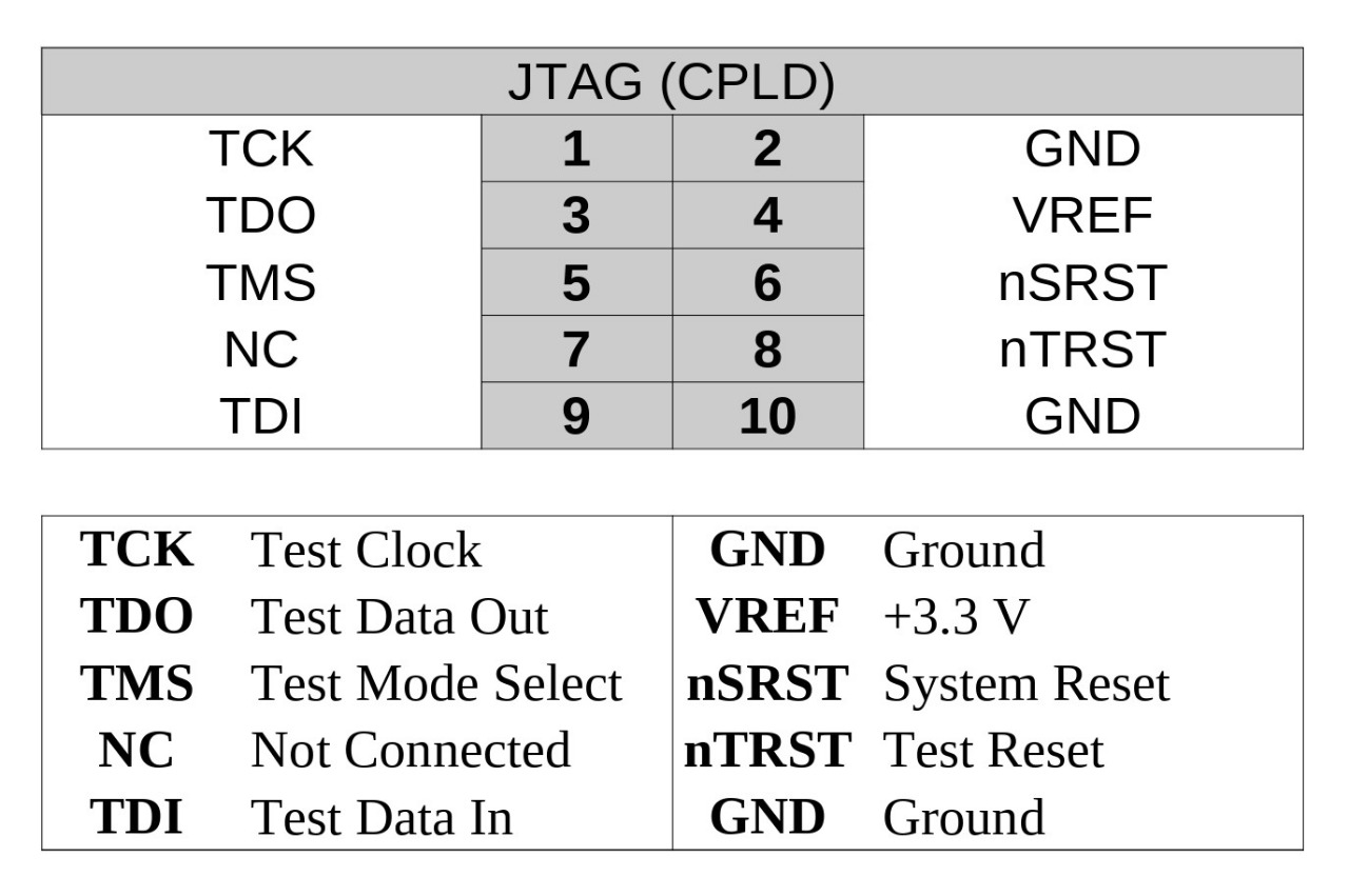
| 1 | AVR-JTAG-10 | Pin_Headers:Pin_Header_Straight_2x05_Pitch2.54mm | JTAG201 |
| 1 | Analog_in | Pin_Headers:Pin_Header_Straight_1x02_Pitch2.54mm | P404 |
| 1 | Analog_out | Pin_Headers:Pin_Header_Straight_1x02_Pitch2.54mm | P303 |
| 1 | C | Capacitors_SMD:C_0805 | C311 |
| 1 | C64AC | Controle:Eurocard_template | P201 |
| 1 | CONN_01X01 | Controle:LNLS_LOGO_Silk | P102 |
| 1 | CONN_01X01 | Pin_Headers:Pin_Header_Straight_1x01_Pitch2.54mm | P402 |
| 1 | CONN_01X01 | Controle:ground_plane_via | P306 |
| 1 | CONN_01X03 | Pin_Headers:Pin_Header_Straight_1x03_Pitch2.54mm | P203 |
| 1 | CONN_01X04 | Pin_Headers:Pin_Header_Straight_1x04_Pitch2.54mm | P202 |
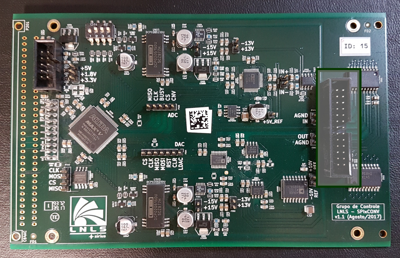
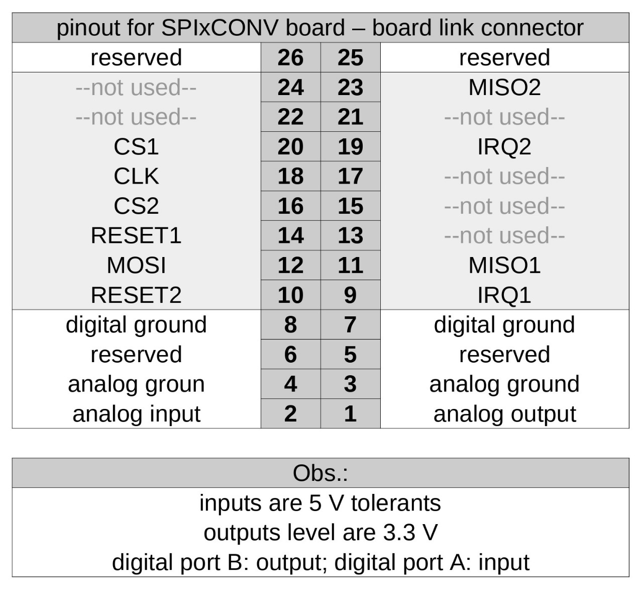
| 1 | CONN_02X13 | Pin_Headers:Pin_Header_Straight_2x13_Pitch2.54mm | P101 |
| 1 | DAC_pins | Pin_Headers:Pin_Header_Straight_1x07_Pitch2.54mm | P304 |
| 1 | DIP_Switch | Controle:DIP_switch_SPST_KAE04LGGT | SW201 |
| 1 | R | Resistors_SMD:R_0805 | R307 |
| 1 | REF5050 | Housings_SOIC:SOIC-8_3.9x4.9mm_Pitch1.27mm | U403 |
| 1 | SPIxxCON | Controle:SPIxxCON_(only_connector) | B201 |
| 1 | W25Q64FV | Housings_SOIC:SOIJ-8_5.3x5.3mm_Pitch1.27mm | U202 |
lnls-sirius/SPIxCONV
This project consists of an 18-bit analog input (ADC) and output (DAC) within a range of 20 V (± 10 V) and 32 digital pins that can be either as inputs or outputs.

lnls-sirius/SPIxCONV
This project consists of an 18-bit analog input (ADC) and output (DAC) within a range of 20 V (± 10 V) and 32 digital pins that can be either as inputs or outputs.

lnls-sirius/SPIxCONV
This project consists of an 18-bit analog input (ADC) and output (DAC) within a range of 20 V (± 10 V) and 32 digital pins that can be either as inputs or outputs.

lnls-sirius/SPIxCONV
This project consists of an 18-bit analog input (ADC) and output (DAC) within a range of 20 V (± 10 V) and 32 digital pins that can be either as inputs or outputs.

travisgoodspeed/goodfet
An embedded bus adapter for various microcontrollers and radios.


ThomasVDD/SmartSupply
SmartSupply is a digital battery powered lab powersupply. It is Arduino compatible and can be controlled via PC over USB.

It measures 160 × 100 mm and has 2 copper layers, 1.6 mm thick.
178 parts, built around the 5M80ZT100A5N, DCP020515DU, LT3080EDD and OPA2277U. The full list of its parts is on this page, with links to each part's symbol and footprint where PCBKit's library has them.
From the lnls-sirius/SPIxCONV repository on GitHub, at the commit this page was made from: the board is hardware/SPIxCONV/PIAD-18bits.kicad_pcb. PCBKit opens the board in the browser, with nothing to install.
Its repository publishes it under the MIT licence: you may reuse it on that licence's terms (keep the author's notice, and for a copyleft licence share your changes alike).