4 layers85 × 41 mm
 Benedikt3141/Smart-Irrigation-System1
A smart irrigation system for irrigation of up to 6 plants. It monitors the moisture, temperature, CO2 concentration, air quality ... and displays the data on a 2.4" TFT Display using an ESP32 DevKit C as processor.
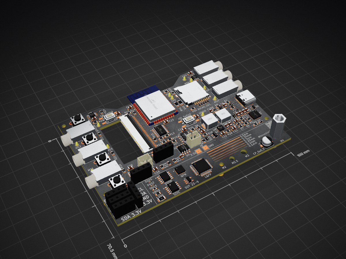
Smart Irrigation SystemV2 is an open-source printed circuit board by Benedikt3141, from the Benedikt3141/Smart-Irrigation-System repository on GitHub, published under the MIT licence. It is a 4-layer board of 100 × 70.5 mm with 147 parts on 135 nets, routed with 1,083 tracks and 143 vias.
It is built around the ESP32-WROOM-32, SN74LVC245APW and ADS1115IDGS, with the TLV62568ADRL, TPS63001DRC and TF-01A among its other parts. Its parts include 43 resistors, 22 capacitors, 15 diodes, 15 connectors and 10 ICs. It belongs with the sensors and measurement boards and the ESP32 boards of this library.


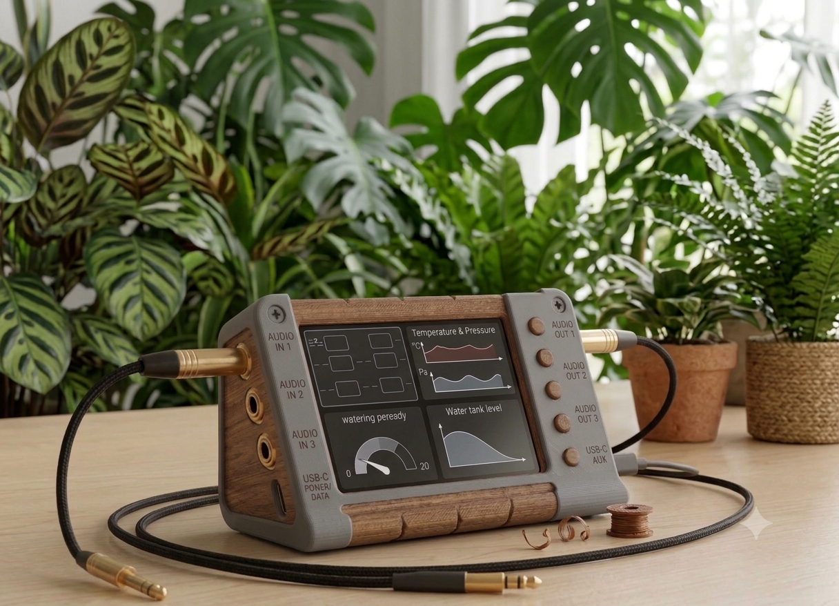
→ AI Preview
The Smart Irrigation System is a battery-powered monitoring and control system for watering up to six individual plants. Each plant is monitored by a capacitive soil moisture sensor connected to the main control unit.
The project currently focuses on the main monitoring and control unit. A separate watering unit is planned but not fully designed yet. Communication between both units is intended to use ESP-NOW.
The system consists of two main parts:
The main unit collects sensor data, displays current measurements on a TFT screen, logs data to an SD card and indicates the system status using an LED strip.
Each soil moisture sensor is connected individually using an audio jack connector.
The watering unit is planned as a separate module. It will receive commands from the main control unit via ESP-NOW and control the water flow using a solenoid valve. The unit should also monitor the water tank level using an ultrasonic sensor.
This part of the system is still work in progress.
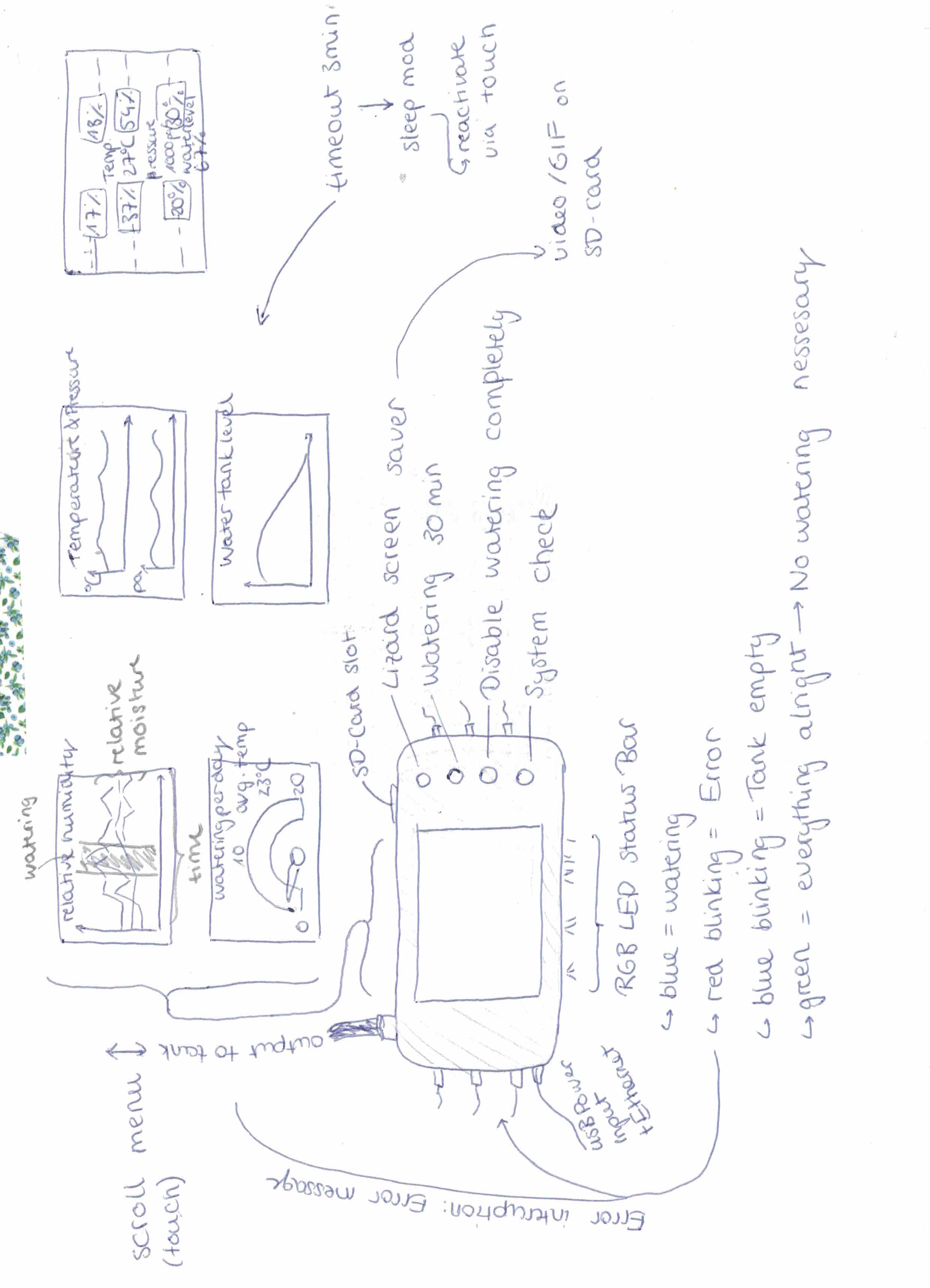
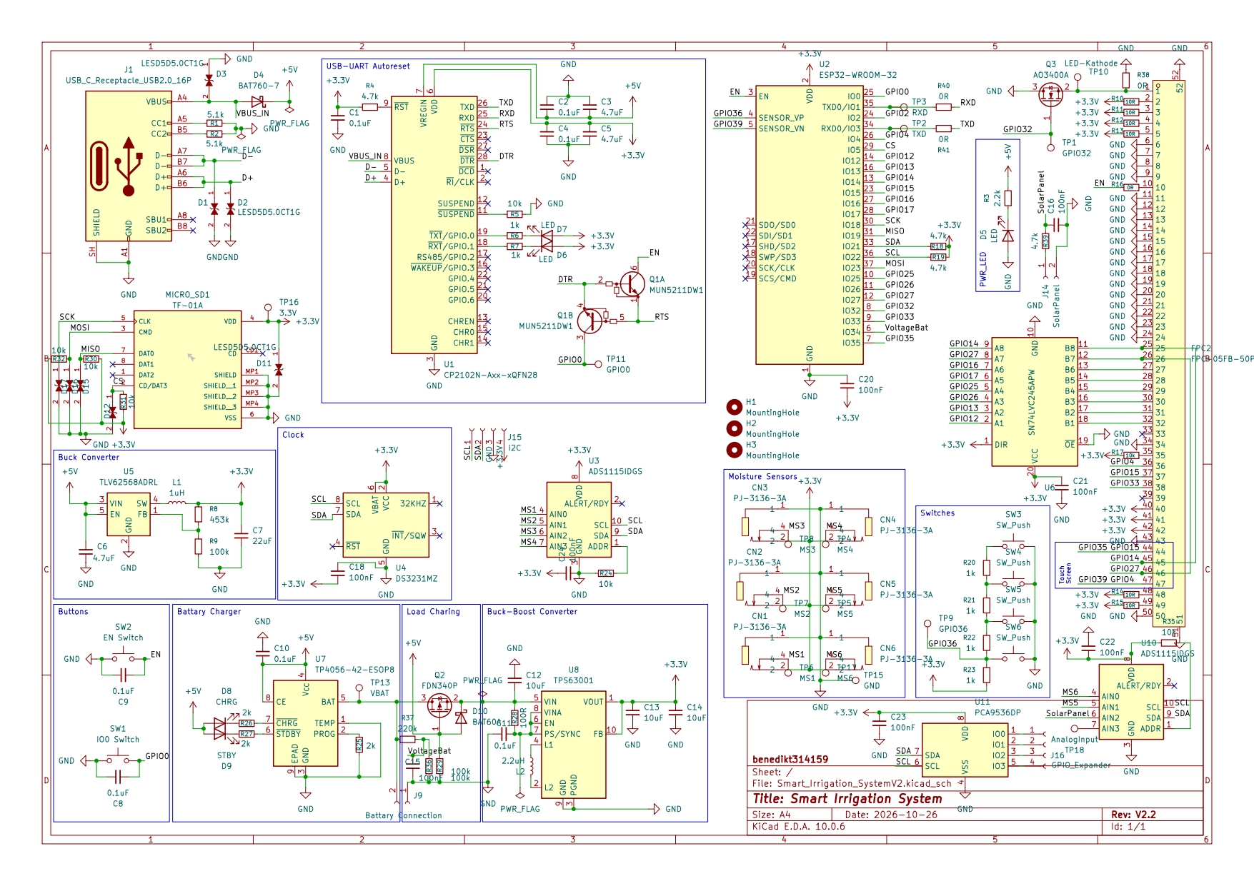
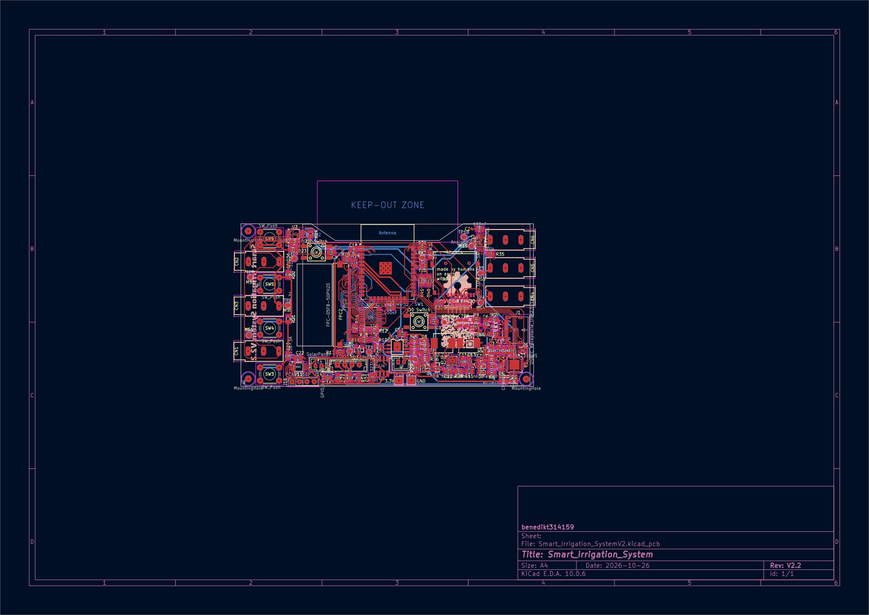
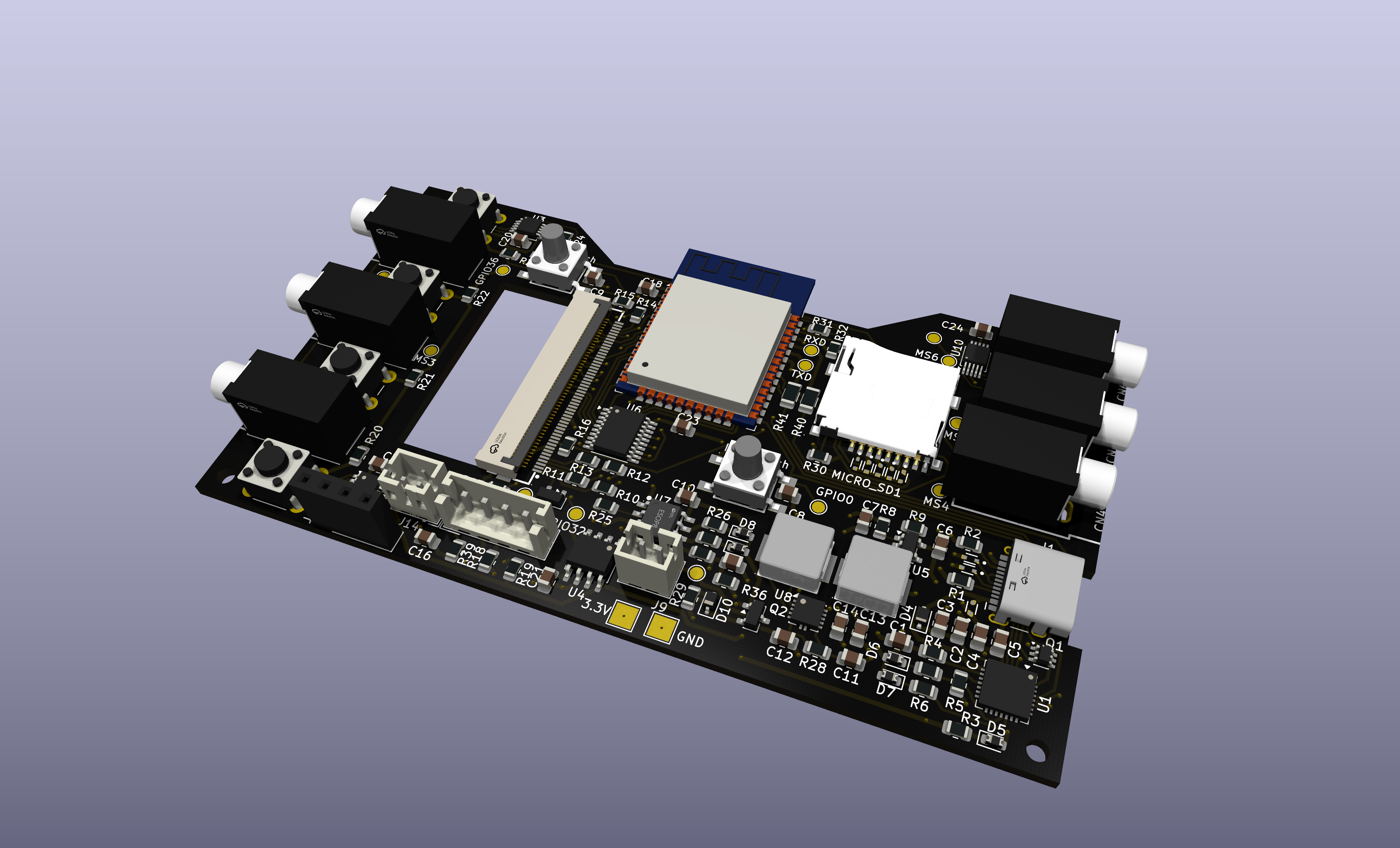
This repository contains both the firmware and the PCB design files.
/firmware/ contains the PlatformIO firmware project./firmware/src/ contains the ESP32 source code./src/pcb/ contains the KiCad PCB design files./src/pcb/gerbers/ contains the exported Gerber files for manufacturing.Smart-Irrigation-System/
├── firmware/
├── images/
├── src/│
│ ├── assembly_and_models/
│ │ ├── SmartIrrigationSystem-Assembly.step
│ │ └── SmartIrrigationSystem.FCStd
│ └── pcb/
│ └── Smart_Irrigation_SytemV2/
├── .gitignore
├── BOM.csv
├── Concept.jpg
├── JOURNAL.md
├── LICENSE
├── README.md
├── cart_adafruit.png
└── cart_jlcpcb.pngTo work with this project, you need:
Use git to clone this repository into your computer.
git clone https://github.com/Benedikt3141/Smart-Irrigation-System.gitOpen the project folder in VS Code and build/upload the firmware using PlatformIO or pioarduino.
You can either use the provided Gerber files or modify the KiCad project and generate new manufacturing files for your preferred PCB supplier.
You can find the gerberfiles here . The correlating BOM.csv and position.csv can be found in the same directories.
This project is still in development.
The main monitoring unit is mostly implemented. The watering unit, web interface and notification system are planned but not finished yet.
Most of the code was written by myself. Since this is a work in progress, the code may still contain bugs or parts that could be improved.
I used AI for debugging assistance, spelling correction, research and for generating the concept visualization shown at the top of this README.
The visualization is intended only as a preview of the planned device and does not represent the final manufactured hardware.
The PCB design, hardware architecture and most of the firmware were created by myself.
| Qty | Value | Footprint | References |
|---|---|---|---|
| 8 | 100nF | Capacitor_SMD:C_0805_2012Metric | C15, C16, C18, C20, C21, C22, C23, C24 |
| 8 | LESD5D5.0CT1G | LESD5D5.0CT1G:TVS_LESD5D5.0CT1G | D1, D2, D3, D11, D12, D15, D16, D17 |
| 7 | 0.1uF | Capacitor_SMD:C_0805_2012Metric | C1, C2, C4, C8, C9, C10, C11 |
| 7 | 10k | Resistor_SMD:R_0805_2012Metric | R5, R17, R24, R30, R31, R32, R35 |
| 6 | 10R | Resistor_SMD:R_0805_2012Metric | R10, R11, R12, R13, R14, R15 |
| 6 | 1k | Resistor_SMD:R_0805_2012Metric | R6, R7, R20, R21, R22, R23 |
| 6 | PJ-3136-3A | C707248:AUDIO-TH_PJ-3136-3A | CN1, CN2, CN3, CN4, CN5, CN6 |
| 5 | I2C | Connector_PinSocket_2.54mm:PinSocket_1x04_P2.54mm_Vertical | J15, J17, J18, J19, J20 |
| 4 | 4.7k | Resistor_SMD:R_0805_2012Metric | R4, R18, R19, R39 |
| 4 | SW_Push | Button_Switch_THT:SW_PUSH_6mm_H5mm | SW3, SW4, SW5, SW6 |
| 3 | 100k | Resistor_SMD:R_0805_2012Metric | R9, R29, R36 |
| 3 | 10uF | Capacitor_SMD:C_0805_2012Metric | C12, C13, C14 |
| 3 | 2k | Resistor_SMD:R_0805_2012Metric | R25, R26, R27 |
| 3 | 4.7uF | Capacitor_SMD:C_0805_2012Metric | C3, C5, C6 |
| 3 | LED | Diode_SMD:D_0603_1608Metric | D5, D6, D7 |
| 3 | MountingHole | MountingHole:MountingHole_2.2mm_M2 | H1, H2, H3 |
| 2 | 0R | Resistor_SMD:R_1206_3216Metric | R40, R41 |
| 2 | 5.1k | Resistor_SMD:R_0805_2012Metric | R1, R2 |
| 2 | ADS1115IDGS | Package_SO:TSSOP-10_3x3mm_P0.5mm | U3, U10 |
| 1 | 0201 | Resistor_SMD:R_0201_0603Metric | R33 |
| 1 | 0402 | Resistor_SMD:R_0402_1005Metric | R34 |
| 1 | 0603 | Resistor_SMD:R_0603_1608Metric | R42 |
| 1 | 0805 | Resistor_SMD:R_0805_2012Metric | R43 |
| 1 | 0R | Resistor_SMD:R_0805_2012Metric | R16 |
| 1 | 100R | Resistor_SMD:R_0805_2012Metric | R28 |
| 1 | 1206 | Resistor_SMD:R_1206_3216Metric | R44 |
| 1 | 1uH | C726315:IND-SMD_L7.1-W6.6 | L1 |
| 1 | 2.2k | Resistor_SMD:R_0805_2012Metric | R3 |
| 1 | 2.2uH | C128686:IND-SMD_L6.6-W6.6 | L2 |
| 1 | 220k | Resistor_SMD:R_0805_2012Metric | R37 |
| 1 | 22uF | Capacitor_SMD:C_0805_2012Metric | C7 |
| 1 | 3.3V | TestPoint:TestPoint_Pad_2.5x2.5mm | TP16 |
| 1 | 453k | Resistor_SMD:R_0805_2012Metric | R8 |
| 1 | AO3400A | Package_TO_SOT_SMD:SOT-23 | Q3 |
| 1 | AnalogInput | TestPoint:TestPoint_Pad_D1.5mm | TP18 |
| 1 | BAT60A | Diode_SMD:D_SOD-323 | D10 |
| 1 | BAT760-7 | Diode_SMD:D_SOD-323F | D4 |
| 1 | Battary Connection | Connector_JST:JST_PH_B2B-PH-K_1x02_P2.00mm_Vertical | J9 |
| 1 | CHRG | Diode_SMD:D_0603_1608Metric | D8 |
| 1 | CP2102N-Axx-xQFN28 | Package_DFN_QFN:QFN-28-1EP_5x5mm_P0.5mm_EP3.35x3.35mm | U1 |
| 1 | DS3231MZ | Package_SO:SOIC-8_3.9x4.9mm_P1.27mm | U4 |
| 1 | EN Switch | C83206:KEY-SMD_4P-L6.0-W6.0-P3.90-LS9.0 | SW2 |
| 1 | ESP32-WROOM-32 | RF_Module:ESP32-WROOM-32 | U2 |
| 1 | FDN340P | Package_TO_SOT_SMD:SOT-23 | Q2 |
| 1 | FPC-05FB-50PH20 | C2856838:FPC-SMD_50P-P0.50_FPC-05FB-50PH20 | FPC2 |
| 1 | GND | TestPoint:TestPoint_Pad_2.5x2.5mm | TP15 |
| 1 | GPIO0 | TestPoint:TestPoint_Pad_D1.5mm | TP11 |
| 1 | GPIO32 | TestPoint:TestPoint_Pad_D1.5mm | TP1 |
| 1 | GPIO36 | TestPoint:TestPoint_Pad_D1.5mm | TP9 |
| 1 | GPIO_Expander | Connector_PinSocket_2.54mm:PinSocket_1x04_P2.54mm_Vertical | J16 |
| 1 | IO0 Switch | C83206:KEY-SMD_4P-L6.0-W6.0-P3.90-LS9.0 | SW1 |
| 1 | LED-Kathode | TestPoint:TestPoint_Pad_D1.5mm | TP10 |
| 1 | MS1 | TestPoint:TestPoint_Pad_D1.5mm | TP6 |
| 1 | MS2 | TestPoint:TestPoint_Pad_D1.5mm | TP7 |
| 1 | MS3 | TestPoint:TestPoint_Pad_D1.5mm | TP8 |
| 1 | MS4 | TestPoint:TestPoint_Pad_D1.5mm | TP4 |
| 1 | MS5 | TestPoint:TestPoint_Pad_D1.5mm | TP5 |
| 1 | MS6 | TestPoint:TestPoint_Pad_D1.5mm | TP17 |
| 1 | MUN5211DW1 | Package_TO_SOT_SMD:SOT-363_SC-70-6 | Q1 |
| 1 | PCA9536DP | Package_SO:TSSOP-8_3x3mm_P0.65mm | U11 |
| 1 | RXD | TestPoint:TestPoint_Pad_D1.5mm | TP3 |
| 1 | SN74LVC245APW | Package_SO:TSSOP-20_4.4x6.5mm_P0.65mm | U6 |
| 1 | STBY | Diode_SMD:D_0603_1608Metric | D9 |
| 1 | SolarPanel | Connector_JST:JST_PH_B2B-PH-K_1x02_P2.00mm_Vertical | J14 |
| 1 | TF-01A | C91145:TF-SMD_TF-01A | MICRO_SD1 |
| 1 | TLV62568ADRL | Package_TO_SOT_SMD:SOT-23-5 | U5 |
| 1 | TP4056-42-ESOP8 | C16581:ESOP-8_L4.9-W3.9-P1.27-LS6.0-BL-EP | U7 |
| 1 | TPS63001 | Package_SON:VSON-10-1EP_3x3mm_P0.5mm_EP1.65x2.4mm_ThermalVias | U8 |
| 1 | TXD | TestPoint:TestPoint_Pad_D1.5mm | TP2 |
| 1 | USB_C_Receptacle_USB2.0_16P | Connector_USB:USB_C_Receptacle_HCTL_HC-TYPE-C-16P-01A | J1 |
| 1 | VBAT | TestPoint:TestPoint_Pad_D1.5mm | TP13 |
The 137 most common of 147 parts.

Gamecard/k2-plus-cm5
K2 Plus CM5 – Creality K2 Plus mit Upstream-Klipper auf einem Raspberry Pi CM5

oceanye/ESP32_C73-MF1750
ESP32-S3 driver and frozen Rev A1 hardware baseline for the MF-1750 dual-SPD1657B six-color e-paper panel


matveylapin/CopterCat_cm4
Полётный контроллер для стандарта FMU-v6u. Обычно на дронах для программирования устанавливают полётный контроллер, одноплатный компьютер и иногда arduino.

t3mschm2d/esp32-tiny-led-controller
The main goal of this project is to develop an OpenHardware board for controlling digital LED strips. The control shall be done via Homeassistant and esphome.The PCB is based around an ESP32-U4WDH microcontroller and…

Duckle29/PWM-to-fan
A small board for controlling two DC fans from an open-drain inverted PWM output.
It measures 100 × 70.5 mm and has 4 copper layers, 1.6 mm thick.
147 parts, built around the ESP32-WROOM-32, SN74LVC245APW, ADS1115IDGS and TLV62568ADRL. The full list of its parts is on this page, with links to each part's symbol and footprint where PCBKit's library has them.
From the Benedikt3141/Smart-Irrigation-System repository on GitHub, at the commit this page was made from: the board is src/pcb/Smart_Irrigation_SystemV2/Smart_Irrigation_SystemV2.kicad_pcb and its schematic src/pcb/Smart_Irrigation_SystemV2/Smart_Irrigation_SystemV2.kicad_sch. PCBKit opens the board in the browser, with nothing to install.
Its repository publishes it under the MIT licence: you may reuse it on that licence's terms (keep the author's notice, and for a copyleft licence share your changes alike).