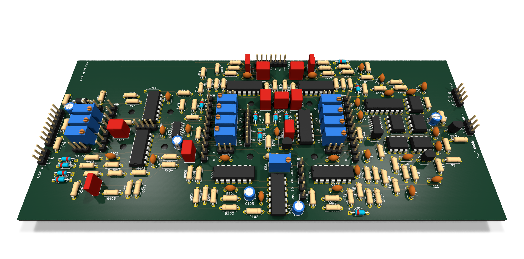
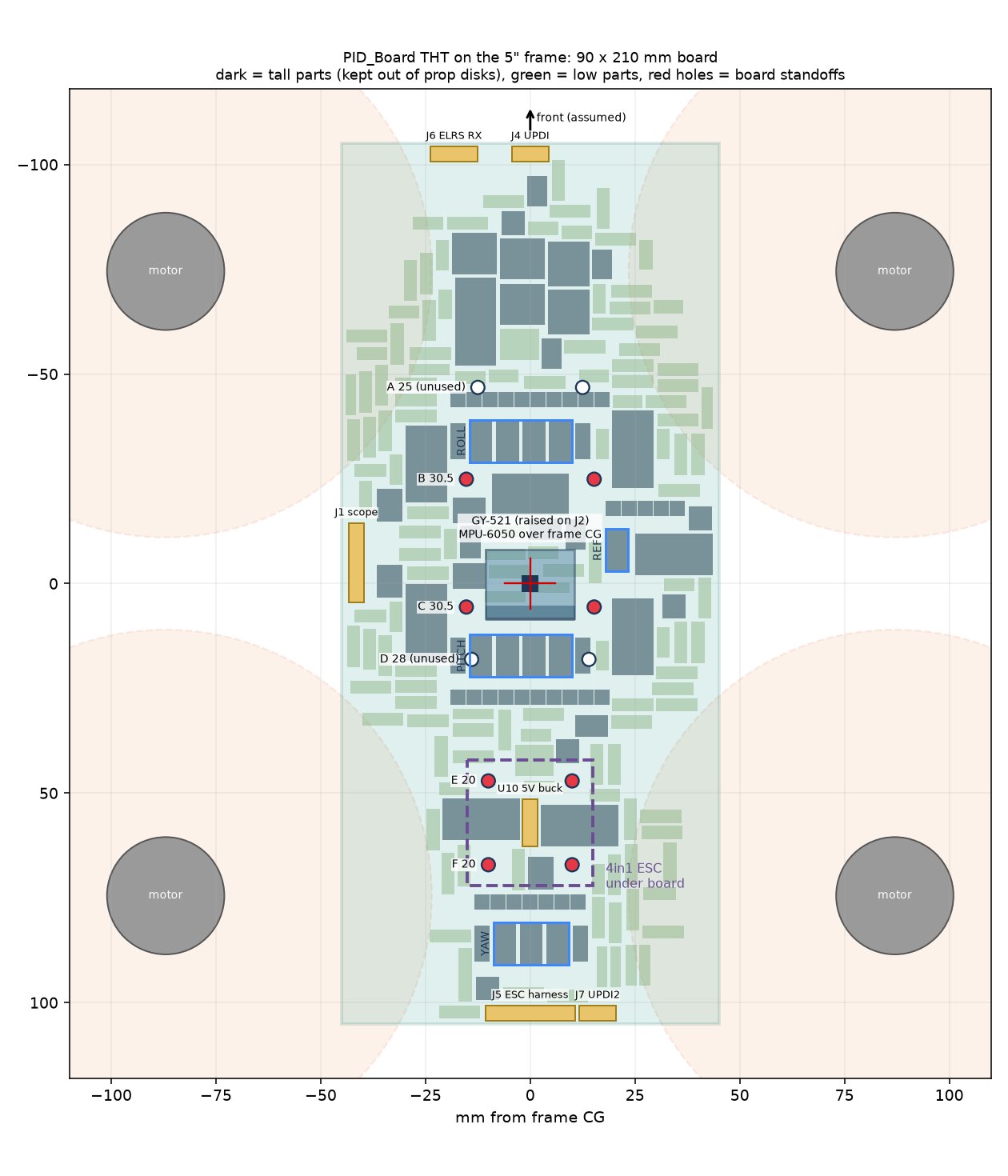
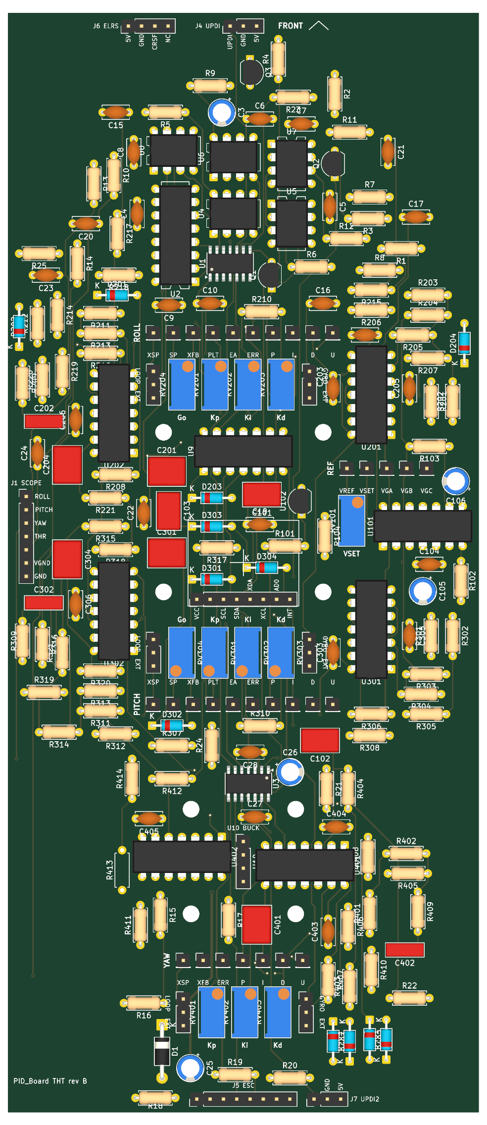
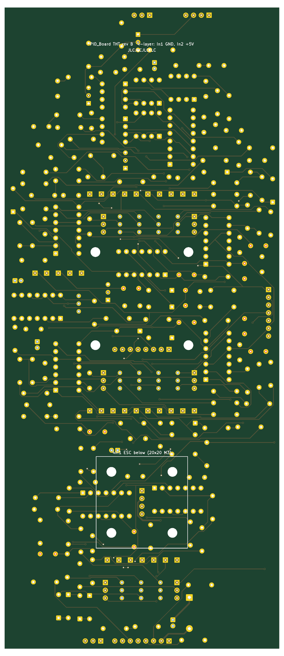
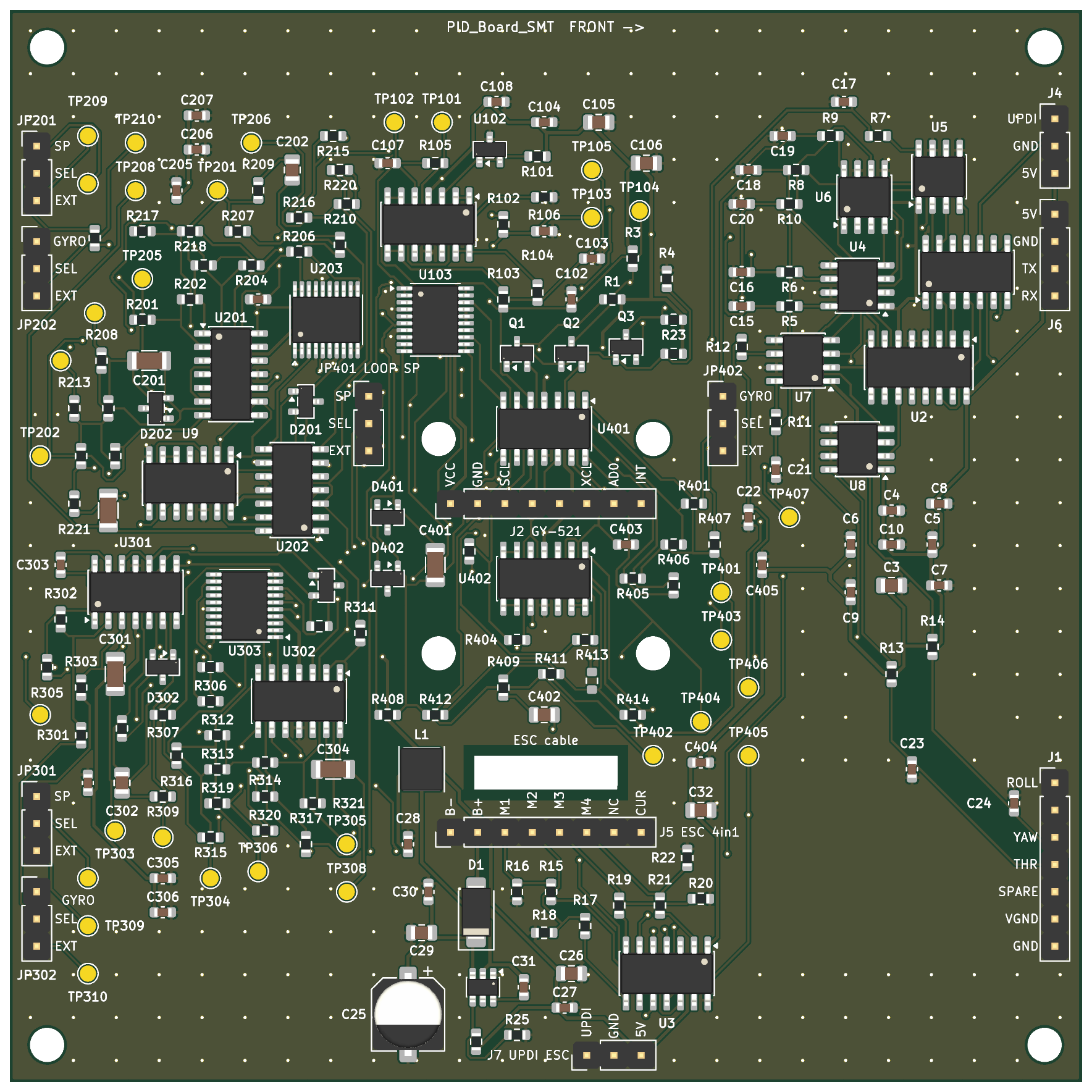
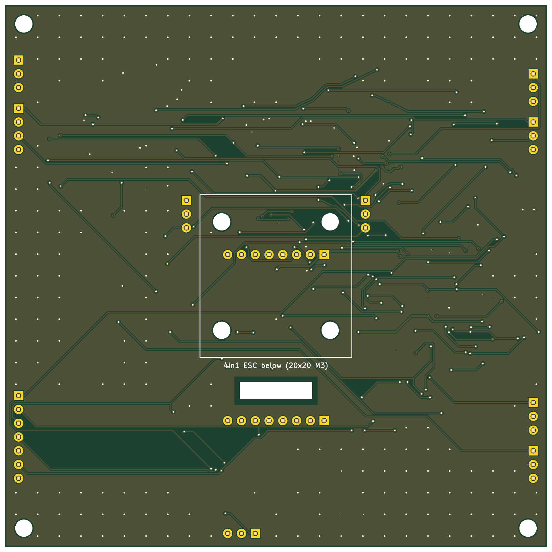
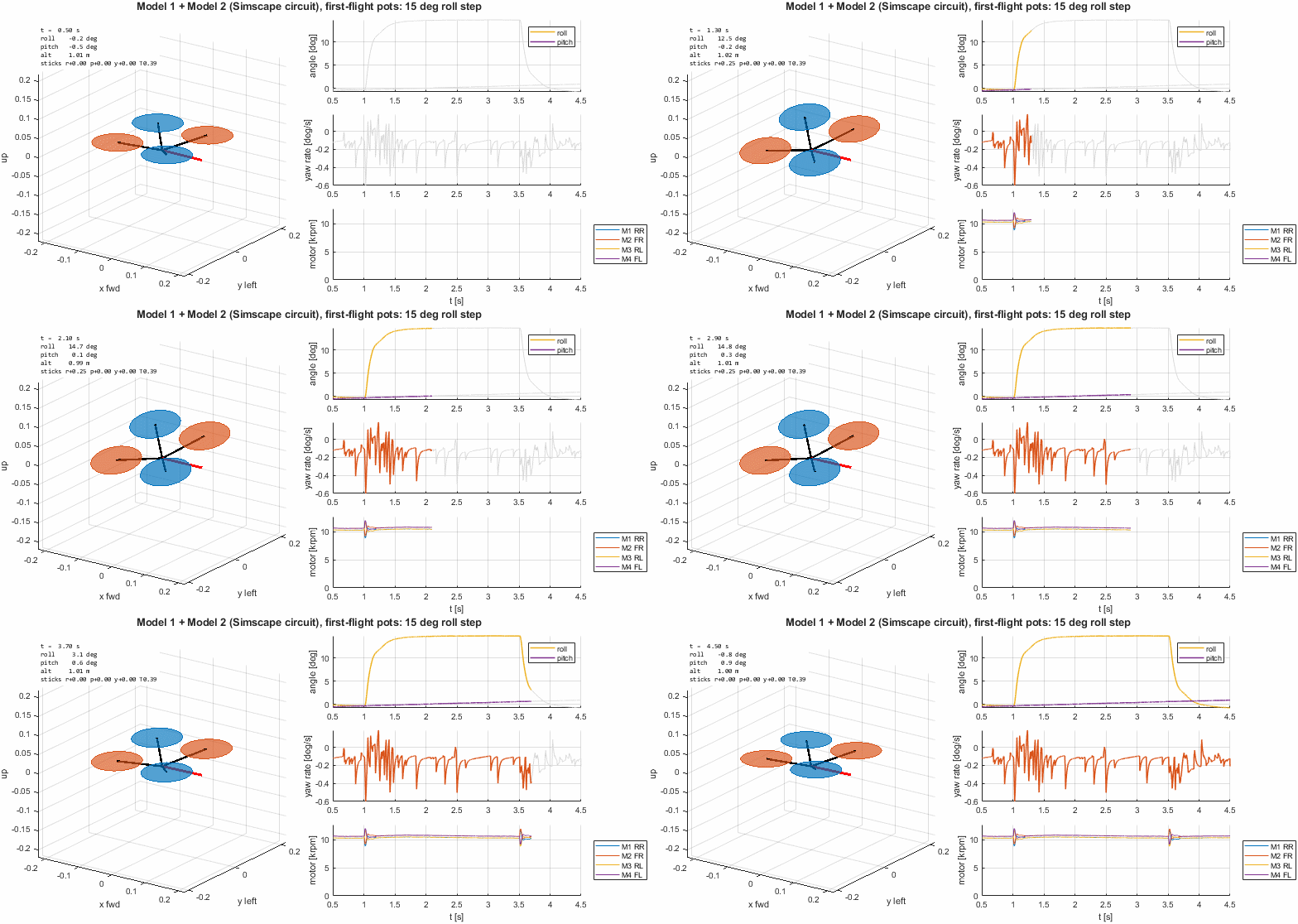
| 36 | 10k | Resistor_THT:R_Axial_DIN0207_L6.3mm_D2.5mm_P7.62mm_Horizontal | R2, R24, R25, R201, R202, R203, R204, R211, R212, R213, R214, R215, R216, R217, R218, R220 +20 |
| 16 | 100nF X7R | Capacitor_THT:C_Disc_D5.0mm_W2.5mm_P5.00mm | C4, C5, C6, C7, C8, C9, C10, C27, C28, C104, C205, C206, C305, C306, C404, C405 |
| 15 | 1k | Resistor_THT:R_Axial_DIN0207_L6.3mm_D2.5mm_P7.62mm_Horizontal | R5, R6, R7, R8, R9, R10, R11, R12, R13, R14, R15, R17, R19, R21, R101 |
| 12 | 1N4148 | Diode_THT:D_DO-35_SOD27_P7.62mm_Horizontal | D201, D202, D203, D204, D301, D302, D303, D304, D401, D402, D403, D404 |
| 10 | 1uF | Capacitor_THT:C_Disc_D5.0mm_W2.5mm_P5.00mm | C15, C16, C17, C18, C19, C20, C21, C22, C23, C24 |
| 8 | MountingHole | MountingHole:MountingHole_3.2mm_M3 | H1, H2, H3, H4, H5, H6, H7, H8 |
| 7 | MCP6004 | Package_DIP:DIP-14_W7.62mm | U101, U201, U202, U301, U302, U401, U402 |
| 6 | 47k | Resistor_THT:R_Axial_DIN0207_L6.3mm_D2.5mm_P7.62mm_Horizontal | R205, R210, R305, R310, R405, R410 |
| 5 | 1uF film | Capacitor_THT:C_Rect_L7.2mm_W5.5mm_P5.00mm_FKS2_FKP2_MKS2_MKP2 | C201, C204, C301, C304, C401 |
| 5 | 2.2k | Resistor_THT:R_Axial_DIN0207_L6.3mm_D2.5mm_P7.62mm_Horizontal | R16, R18, R20, R22, R23 |
| 5 | 4.7k | Resistor_THT:R_Axial_DIN0207_L6.3mm_D2.5mm_P7.62mm_Horizontal | R1, R3, R206, R306, R406 |
| 5 | MCP4822 | Package_DIP:DIP-8_W7.62mm | U4, U5, U6, U7, U8 |
| 4 | 10uF | Capacitor_THT:CP_Radial_D5.0mm_P2.00mm | C3, C26, C105, C106 |
| 3 | 100 | Resistor_THT:R_Axial_DIN0207_L6.3mm_D2.5mm_P7.62mm_Horizontal | R102, R103, R104 |
| 3 | 100k, set 50k (Kd 9.7 ms) | Potentiometer_THT:Potentiometer_Bourns_3296W_Vertical | RV203, RV303, RV403 |
| 3 | 100k, set 50k (Kp 1.16) | Potentiometer_THT:Potentiometer_Bourns_3296W_Vertical | RV201, RV301, RV401 |
| 3 | 100nF film | Capacitor_THT:C_Rect_L7.2mm_W2.5mm_P5.00mm_FKS2_FKP2_MKS2_MKP2 | C202, C302, C402 |
| 3 | 10nF C0G | Capacitor_THT:C_Disc_D5.0mm_W2.5mm_P5.00mm | C203, C303, C403 |
| 3 | 1M | Resistor_THT:R_Axial_DIN0207_L6.3mm_D2.5mm_P7.62mm_Horizontal | R208, R308, R408 |
| 3 | 22k | Resistor_THT:R_Axial_DIN0207_L6.3mm_D2.5mm_P7.62mm_Horizontal | R4, R221, R321 |
| 3 | 27k | Resistor_THT:R_Axial_DIN0207_L6.3mm_D2.5mm_P7.62mm_Horizontal | R209, R309, R409 |
| 3 | 2N7000 | Package_TO_SOT_THT:TO-92_Inline_Wide | Q1, Q2, Q3 |
| 3 | 470nF film | Capacitor_THT:C_Rect_L7.2mm_W4.5mm_P5.00mm_FKS2_FKP2_MKS2_MKP2 | C101, C102, C103 |
| 3 | D_OUT | Connector_PinHeader_2.54mm:PinHeader_1x01_P2.54mm_Vertical | TP204, TP304, TP404 |
| 3 | EXT_FB | Connector_PinHeader_2.54mm:PinHeader_1x01_P2.54mm_Vertical | TP210, TP310, TP407 |
| 3 | EXT_SP | Connector_PinHeader_2.54mm:PinHeader_1x01_P2.54mm_Vertical | TP209, TP309, TP406 |
| 3 | I_OUT | Connector_PinHeader_2.54mm:PinHeader_1x01_P2.54mm_Vertical | TP203, TP303, TP403 |
| 3 | LOOP_FB: 1-2 gyro, 2-3 bench | Connector_PinHeader_2.54mm:PinHeader_1x03_P2.54mm_Vertical | JP202, JP302, JP402 |
| 3 | LOOP_SP: 1-2 closed, 2-3 bench | Connector_PinHeader_2.54mm:PinHeader_1x03_P2.54mm_Vertical | JP201, JP301, JP401 |
| 3 | P_OUT | Connector_PinHeader_2.54mm:PinHeader_1x01_P2.54mm_Vertical | TP202, TP302, TP402 |
| 2 | 100k, set 67k (Ki 10/s) | Potentiometer_THT:Potentiometer_Bourns_3296W_Vertical | RV202, RV302 |
| 2 | 20k | Resistor_THT:R_Axial_DIN0207_L6.3mm_D2.5mm_P7.62mm_Horizontal | R219, R319 |
| 2 | 33k | Resistor_THT:R_Axial_DIN0207_L6.3mm_D2.5mm_P7.62mm_Horizontal | R207, R307 |
| 2 | 50k, set 25k (Go 1.75) | Potentiometer_THT:Potentiometer_Bourns_3296W_Vertical | RV204, RV304 |
| 2 | ATtiny1614-SS | Package_SO:SOIC-14_3.9x8.7mm_P1.27mm | U1, U3 |
| 2 | E_A | Connector_PinHeader_2.54mm:PinHeader_1x01_P2.54mm_Vertical | TP206, TP306 |
| 2 | PLANT_OUT | Connector_PinHeader_2.54mm:PinHeader_1x01_P2.54mm_Vertical | TP208, TP308 |
| 1 | 100k, set mid | Potentiometer_THT:Potentiometer_Bourns_3296W_Vertical | RV402 |
| 1 | 10k (wiper-GND 8.1k) | Potentiometer_THT:Potentiometer_Bourns_3296W_Vertical | RV101 |
| 1 | 10k DNP | Resistor_THT:R_Axial_DIN0207_L6.3mm_D2.5mm_P7.62mm_Horizontal | R413 |
| 1 | 15k | Resistor_THT:R_Axial_DIN0207_L6.3mm_D2.5mm_P7.62mm_Horizontal | R407 |
| 1 | 1N5817 | Diode_THT:D_DO-41_SOD81_P10.16mm_Horizontal | D1 |
| 1 | 47uF 25V | Capacitor_THT:CP_Radial_D5.0mm_P2.00mm | C25 |
| 1 | 5V buck module (Mini 5V 3A) | Connector_PinHeader_2.54mm:PinHeader_1x04_P2.54mm_Vertical | U10 |
| 1 | 74HC138 | Package_DIP:DIP-16_W7.62mm | U2 |
| 1 | Axis_Mon | Connector_PinHeader_2.54mm:PinHeader_1x07_P2.54mm_Vertical | J1 |
| 1 | CD4066BE | Package_DIP:DIP-14_W7.62mm | U9 |
| 1 | ELRS_RX | Connector_PinHeader_2.54mm:PinHeader_1x04_P2.54mm_Vertical | J6 |
| 1 | ESC_4in1 | Connector_PinHeader_2.54mm:PinHeader_1x08_P2.54mm_Vertical | J5 |
| 1 | E_PR | Connector_PinHeader_2.54mm:PinHeader_1x01_P2.54mm_Vertical | TP301 |
| 1 | E_RR | Connector_PinHeader_2.54mm:PinHeader_1x01_P2.54mm_Vertical | TP201 |
| 1 | E_YR | Connector_PinHeader_2.54mm:PinHeader_1x01_P2.54mm_Vertical | TP401 |
| 1 | IMU_GY521 | Connector_PinHeader_2.54mm:PinHeader_1x08_P2.54mm_Vertical | J2 |
| 1 | PITCH_RATE_SP | Connector_PinHeader_2.54mm:PinHeader_1x01_P2.54mm_Vertical | TP307 |
| 1 | ROLL_RATE_SP | Connector_PinHeader_2.54mm:PinHeader_1x01_P2.54mm_Vertical | TP207 |
| 1 | TL431ACLPG | Package_TO_SOT_THT:TO-92_Inline_Wide | U102 |
| 1 | UPDI | Connector_PinHeader_2.54mm:PinHeader_1x03_P2.54mm_Vertical | J4 |
| 1 | UPDI2 | Connector_PinHeader_2.54mm:PinHeader_1x03_P2.54mm_Vertical | J7 |
| 1 | U_PITCH | Connector_PinHeader_2.54mm:PinHeader_1x01_P2.54mm_Vertical | TP305 |
| 1 | U_ROLL | Connector_PinHeader_2.54mm:PinHeader_1x01_P2.54mm_Vertical | TP205 |
| 1 | U_YAW | Connector_PinHeader_2.54mm:PinHeader_1x01_P2.54mm_Vertical | TP405 |
| 1 | VGND_A | Connector_PinHeader_2.54mm:PinHeader_1x01_P2.54mm_Vertical | TP103 |
| 1 | VGND_B | Connector_PinHeader_2.54mm:PinHeader_1x01_P2.54mm_Vertical | TP104 |
| 1 | VGND_C | Connector_PinHeader_2.54mm:PinHeader_1x01_P2.54mm_Vertical | TP105 |
| 1 | VREF_BUF | Connector_PinHeader_2.54mm:PinHeader_1x01_P2.54mm_Vertical | TP101 |
| 1 | VSET | Connector_PinHeader_2.54mm:PinHeader_1x01_P2.54mm_Vertical | TP102 |