2 layers127 × 100.3 mm
Cross point exp brd mini red2-smd
damercer/Cross-Point-Project
A Software Configurable Solderless Breadboard
129 parts3
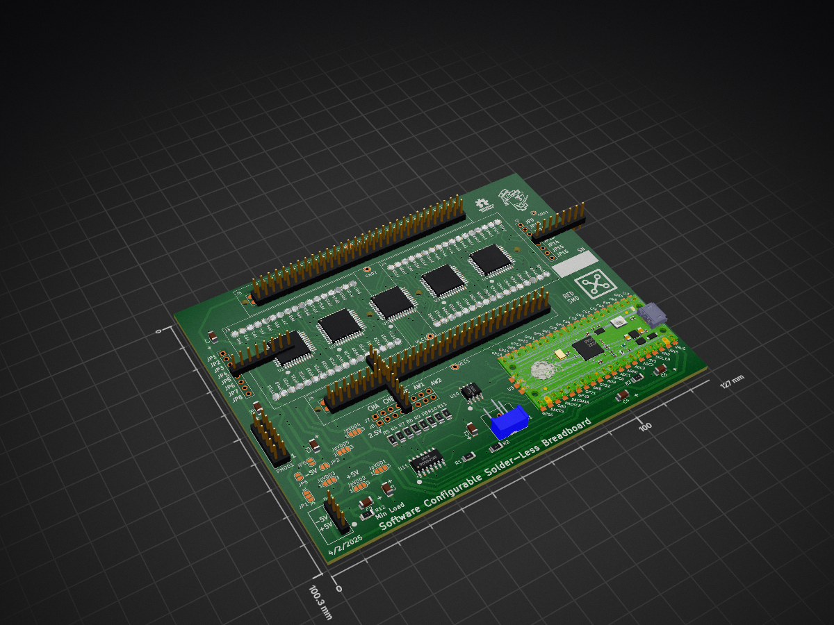
 damercer/Cross-Point-Project3
A Software Configurable Solderless Breadboard
Cross point exp brd mini red2-sjmp is an open-source printed circuit board by damercer, from the damercer/Cross-Point-Project repository on GitHub. It is a 2-layer board of 127 × 100.3 mm with 130 parts on 148 nets, routed with 1,284 tracks and 143 vias.
It is built around the RFM-0505S, MCP4822-E/P and MCP6004-E/P. Its parts include 12 resistors, 8 capacitors, 8 ICs and 8 connectors. It belongs with the RP2040 boards of this library.


Software-Configured Breadboard Hardware Targeting Circuit Wiring Error Reduction in ECE Labs.
Abstract:
The hardware project aims to examine the effectiveness of software-configured wiring compared to traditional manual wiring of breadboards. While both methods use actual hardware, the software-configured approach automates the connections between components, thereby minimizing wiring errors and setup time. The intent is to investigate the impact of each approach on student comprehension, engagement, and error rates. By comparing these two approaches, the project seeks to determine which method better supports student engagement, educational outcomes and reduces frustration associated with complex circuit construction.
Introduction:
Hands-on experiential learning is a cornerstone of ECE education, typically relying on manual wiring of circuits on solderless breadboards. Using a traditional solderless breadboard as the means for building electronic circuit lab experiments requires the student, in addition to placing components, to manually insert wires to connect together the component pins according to a schematic diagram. These manual translation steps from schematic to hardware can lead to wiring errors in the experimental setup that can obscure circuit principles. While this manual wiring method offers valuable experience in physical component handling and troubleshooting, the extra time needed for debugging and correcting these errors leads to frustration and loss of precious lab time to investigate the circuit concept in question.
The goal is to evaluate the educational benefits and potential drawbacks of these software-configured hardware systems compared to traditional manual wiring. By doing so, it addresses the need for balancing hands-on skills with error minimization and conceptual understanding in electrical engineering education.
Analog switch matrix cross point experiment breadboard.
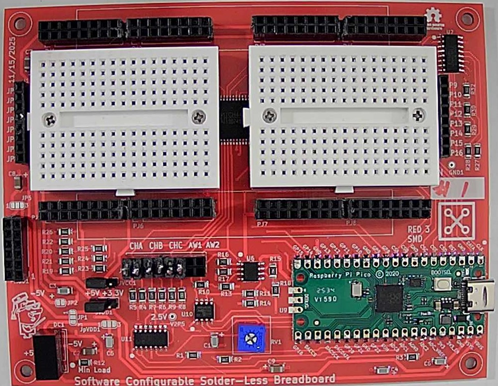 Production PCB (Red3 version, instructions for ordering boards can be found in PCB Projects folder)
The idea is to computerize the wiring of the breadboard in an effort to reduce student frustration when building complex experiments. Using four analog 16X8 cross point switches wired together into two 32X8 cross points with a fifth switch matrix interconnecting the two smaller arrays into effectively a single 64X16 array.
This breadboard makes real, hardware connections between the 64 breadboard component pins on the board to the 16 “jumper” nodes on the board via software commands, instead of needing to manually install jumper wires. The prototype PCB is shown, figure 1, which incorporates two mini 170 pin solderless breadboards, one for each of the 32X8 cross point arrays. There are a combined 68 total component pin locations across both mini breadboards with power distribution strips top and bottom. The two mini breadboards connect to the PCB through pogo pins and so they can be easily removed. It would then be possible to bolt on custom daughter PCBs with whatever components are needed for a given course already installed. Such as CMOS transistor arrays (CD4007) with even some pre-wired sub-circuits like current sources and OTAs.
The combined 64X16 cross point matrix board uses a total of 5 CH446DS 16X8 analog cross point ICs (from China) programed via a RP-2040 micro controller breakout board (Pi Pico or equivalent). Materials cost per board, in quantities of 10 or more, is less than $30 not including the assembly labor.
The board is powered from the Pi Pico USB connection. For powering the experiment circuits, Jumpers can be configured for 0 and +3.3V, 0 and +5V or -5V and +5V power using an on board isolated 5V DC-DC generator. Pi Pico microcontroller internal 12 bit ADC along with an external dual 12 bit DAC provide some level of data acquisition measurement capability for experiments.
LTspice is used to enter the schematic for the experiment. In addition to the standard library symbols a number of supporting schematic library files have been created. Schematic symbols for TO-92 transistors and resistors of various lead spacing are available in the LTspice files.
| Qty | Value | Footprint | References |
|---|---|---|---|
| 68 | POGO_PIN_01X01_70-9150 | MF_Connectors:MF_Connectors-POGO_PIN_70-9150 | PP1, PP2, PP10, PP11, PP12, PP13, PP14, PP15, PP16, PP17, PP18, PP19, PP20, PP21, PP22, PP23 +52 |
| 5 | 0.47u | Capacitor_SMD:C_1206_3216Metric | C1, C3, C4, C5, C6 |
| 5 | CH446DS1 | JumperlessFootprints:LQFP44_Tight | U1, U2, U3, U4, U5 |
| 5 | Conn_01x03_Pin | Jumper:SolderJumper-3_P1.3mm_Bridged12_RoundedPad1.0x1.5mm_NumberLabels | JpVDD1, JpVDD2, JpVDD3, JpVDD4, JpVDD5 |
| 4 | Conn_01x08_Pin | Connector_PinHeader_2.54mm:PinHeader_1x08_P2.54mm_Vertical | J1, J2, J7, J8 |
| 4 | SolderJumper_2_Open | Jumper:SolderJumper-2_P1.3mm_Open_RoundedPad1.0x1.5mm | JP3, JP4, JP5, JP6 |
| 4 | TestPoint | TestPoint:TestPoint_THTPad_D2.0mm_Drill1.0mm | GND2, VCC1, VDD1, VEE1 |
| 3 | 10u | Capacitor_SMD:C_1206_3216Metric | C2, C7, C8 |
| 3 | 220 | Resistor_SMD:R_1206_3216Metric | R1, R2, R3 |
| 3 | 330k | Resistor_SMD:R_1206_3216Metric | R4, R6, R8 |
| 3 | 680k | Resistor_SMD:R_1206_3216Metric | R5, R7, R9 |
| 2 | Solderless_mini_2Rows-17Pins | Library:Solderless_mini_mount_holes_2x17_P2.54mm | J3, J4 |
| 2 | Solderless_power-4Pins | Library:Solderless_power_2x4_P2.54mm | J5, J6 |
| 1 | 10k | Potentiometer_THT:Potentiometer_Bourns_3386P_Vertical | RV1 |
| 1 | 33k | Resistor_SMD:R_1206_3216Metric | R10 |
| 1 | 510 | Resistor_SMD:R_1206_3216Metric | R12 |
| 1 | 68k | Resistor_SMD:R_1206_3216Metric | R11 |
| 1 | Conn_02x06_Top_Bottom | Library:PMOD_Header_2x06_P2.54mm | PMOD1 |
| 1 | DNP | Library:Proffessor | |
| 1 | LOGO | Library:xlab-logo3 | G*** |
| 1 | MCP4822 | Package_SO:SO-8_3.9x4.9mm_P1.27mm | U10 |
| 1 | MCP6004 | Package_SO:SO-14_3.9x8.65mm_P1.27mm | U11 |
| 1 | Pico | MCU_RaspberryPi_and_Boards:RPi_Pico_SMD_TH | U9 |
| 1 | RFM-0505S | Library:RFM-0505S | DC1 |
| 1 | SolderJumper_2_Bridged | Jumper:SolderJumper-2_P1.3mm_Bridged_RoundedPad1.0x1.5mm | JP2 |
| 1 | SolderJumper_3_Open | Jumper:SolderJumper-3_P1.3mm_Open_RoundedPad1.0x1.5mm_NumberLabels | JP1 |
| 1 | TestPoint | TestPoint:TestPoint_THTPad_D1.5mm_Drill0.7mm | GND1 |
The 125 most common of 130 parts.
damercer/Cross-Point-Project
A Software Configurable Solderless Breadboard

damercer/Cross-Point-Project
A Software Configurable Solderless Breadboard

damercer/Cross-Point-Project
A Software Configurable Solderless Breadboard

damercer/Cross-Point-Project
A Software Configurable Solderless Breadboard

damercer/Cross-Point-Project
A Software Configurable Solderless Breadboard

sebastianbeyer/KOSMO_braids
This is a KOSMO (Look Mum No Computer) version of the Mutable instruments braids, based on the through-hole version done by sound-force.nl.


AaronDoubert/quadcopter-pid-boards
Analog PID flight controller for a 5" quadcopter: roll, pitch and yaw loops built from op-amps and trimpots, fed by an MPU-6050 through a small ATtiny/DAC "shim", driving a 4in1 ESC. Designed in KiCad 10.

Oblique-Industry/Oblique-Easel
Code, Electronics, and Industrial Design for the Oblique Easel Artmaschine Cyberdeck

schlae/pico-dram-tester
Raspberry Pi Pico 2 Vintage DRAM Tester


PSU-Ext-Org/psu-ext-hardware
A repository to store PSU-EXT hardware design assets, schematics, circuit diagrams, CAD files and manufacturing data.

It measures 127 × 100.3 mm and has 2 copper layers, 1.6 mm thick.
130 parts, built around the RFM-0505S, MCP4822-E/P and MCP6004-E/P. The full list of its parts is on this page, with links to each part's symbol and footprint where PCBKit's library has them.
From the damercer/Cross-Point-Project repository on GitHub, at the commit this page was made from: the board is PCB Projects/cross-point-exp-brd-mini-red2-sjmp/cross-point-exp-brd-mini-red2-sjmp-backups/cross-point-exp-brd-mini-red2-sjmp-2025-04-08_131042/cross-point-exp-brd-mini-red2-sjmp.kicad_pcb and its schematic PCB Projects/cross-point-exp-brd-mini-blue/cross-point-exp-brd-mini-lc.kicad_sch. PCBKit opens the board in the browser, with nothing to install.
Its repository states no licence, so its author keeps all rights: ask damercer before reusing the design.