2 layers98.8 × 98.4 mm

 0sleep/lwLIDAR
Open-source light-weight 3D LiDAR based on a flexible PCB
Mcu board is an open-source printed circuit board by 0sleep, from the 0sleep/lwLIDAR repository on GitHub, published under the AGPL-3.0 licence. It is a 2-layer board of 31.5 × 75 mm with 91 parts on 96 nets, routed with 709 tracks and 174 vias.
It is built around the ESP32-S3-WROOM-1-N8, LIS2MDL and TXS0102DCU, with the DW01A, LSM6DSO and TLV75801PDBV among its other parts. Its parts include 25 capacitors, 23 resistors, 10 ICs, 6 connectors and 4 diodes. It belongs with the microcontroller boards boards and the ESP32 boards of this library.


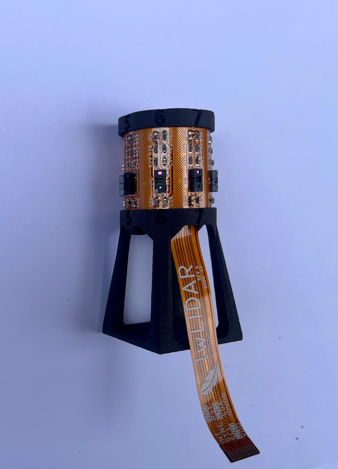
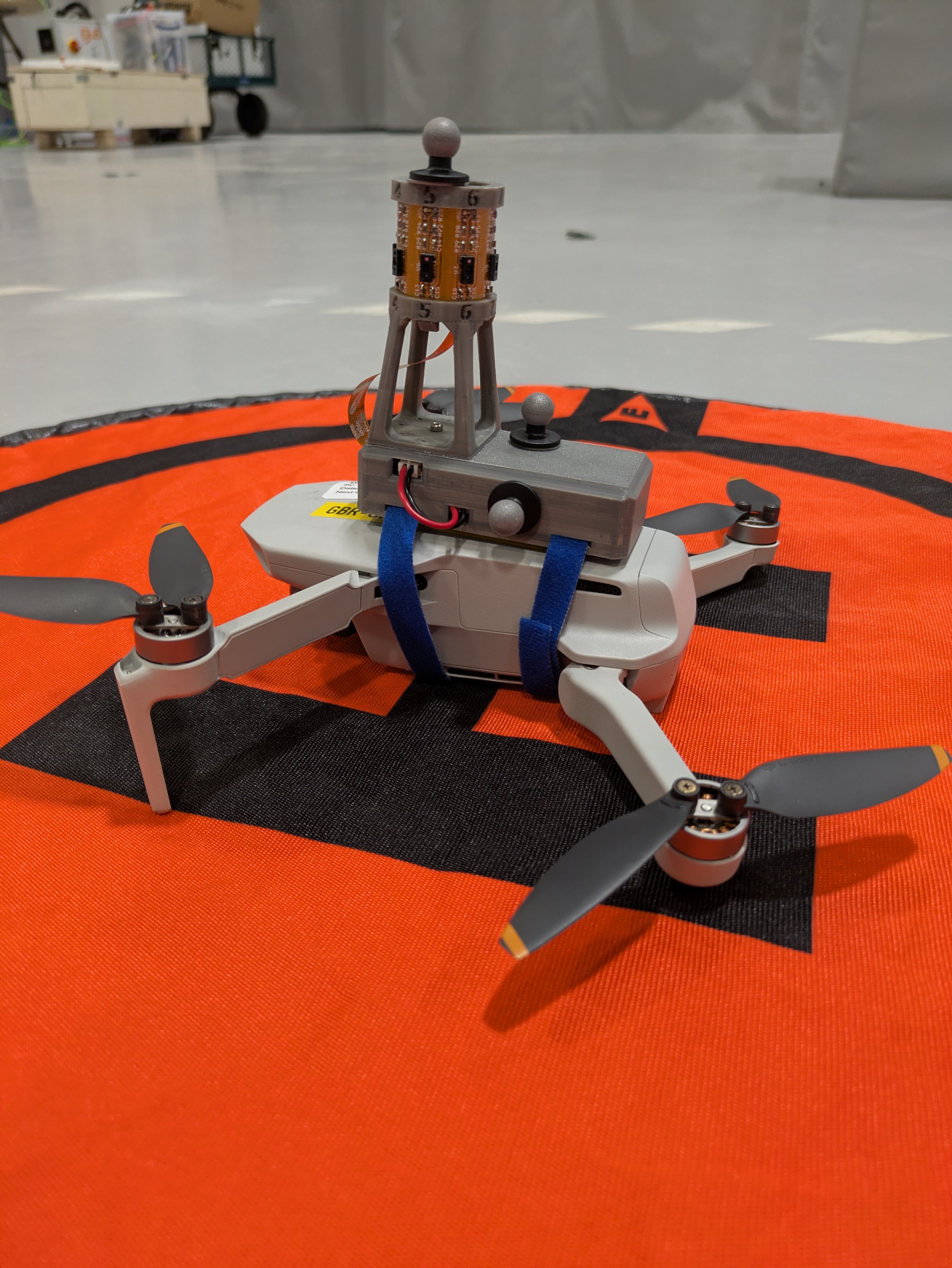
lwLIDAR is a research project aiming to design, implement and test a low-cost compact 3D LiDAR for use in constrained robotics research. It consists of an array of 8 VL53L8CX 8x8 matrix LiDAR sensors mounted to a flexible PCB.
This repository contains all required design files to construct and program a lwLIDAR sensor with an interface board to act as a sample implementation. Each subdirectory contains a more detailed README file.
|-------------------|-------------------------| | Framerate | 16 Hz | | Maximum distance | 4 m | | Resolution | 8 v x256 h | | FoV | 45° v x 360° h | | Size | 31x31x67 mm (with mast) | | Weight | 11g |
| Power consumption | 1.5W |
|---|
This project is licensed under the GNU AGPL license (see LICENSE.txt).
If you have improvements or want this repo to link to a usecase you made, please submit a pull request! If you have problems, please open an issue - I'm happy to improve this repository over time!
| Qty | Value | Footprint | References |
|---|---|---|---|
| 7 | 0.1uF | Capacitor_SMD:C_0603_1608Metric_Pad1.08x0.95mm_HandSolder | C1, C10, C13, C22, C23, C24, C25 |
| 7 | 10k | Resistor_SMD:R_0603_1608Metric_Pad0.98x0.95mm_HandSolder | R6, R7, R9, R13, R14, R15, R21 |
| 6 | 100nF | Capacitor_SMD:C_0603_1608Metric_Pad1.08x0.95mm_HandSolder | C4, C6, C14, C15, C17, C19 |
| 4 | 10uF | Capacitor_SMD:C_0603_1608Metric_Pad1.08x0.95mm_HandSolder | C2, C3, C5, C18 |
| 3 | Conn_01x01 | MountingHole:MountingHole_2.5mm_Pad_Via | MH1, MH2, MH3 |
| 3 | DNP | Resistor_SMD:R_0603_1608Metric_Pad0.98x0.95mm_HandSolder | R12, R22, R23 |
| 3 | NC | Resistor_SMD:R_0603_1608Metric_Pad0.98x0.95mm_HandSolder | R16, R17, R18 |
| 3 | TestPoint | TestPoint:TestPoint_Pad_D1.0mm | RX, TP1, TX |
| 2 | 0R | Resistor_SMD:R_0603_1608Metric_Pad0.98x0.95mm_HandSolder | R10, R11 |
| 2 | 12pf NC | Capacitor_SMD:C_0603_1608Metric_Pad1.08x0.95mm_HandSolder | C20, C21 |
| 2 | 330R | Resistor_SMD:R_0603_1608Metric_Pad0.98x0.95mm_HandSolder | R5, R19 |
| 2 | 5.1k | Resistor_SMD:R_0603_1608Metric_Pad0.98x0.95mm_HandSolder | R1, R2 |
| 2 | DNP | Capacitor_SMD:C_0603_1608Metric_Pad1.08x0.95mm_HandSolder | C11, C12 |
| 2 | LED | LED_SMD:LED_0603_1608Metric_Pad1.05x0.95mm_HandSolder | D1, D3 |
| 2 | Selector | Jumper:SolderJumper-3_P1.3mm_Bridged12_RoundedPad1.0x1.5mm_NumberLabels | JP5, JP6 |
| 2 | TXS0102DCU | Package_SO:VSSOP-8_2.3x2mm_P0.5mm | U8, U10 |
| 1 | 0.4R | Resistor_SMD:R_0603_1608Metric_Pad0.98x0.95mm_HandSolder | R20 |
| 1 | 1.2k | Resistor_SMD:R_0603_1608Metric_Pad0.98x0.95mm_HandSolder | R_PROG1 |
| 1 | 100R | Resistor_SMD:R_0603_1608Metric_Pad0.98x0.95mm_HandSolder | R3 |
| 1 | 100uF | Capacitor_SMD:C_0603_1608Metric_Pad1.08x0.95mm_HandSolder | C7 |
| 1 | 1k | Resistor_SMD:R_0603_1608Metric_Pad0.98x0.95mm_HandSolder | R4 |
| 1 | 1uF | Capacitor_SMD:C_0603_1608Metric_Pad1.08x0.95mm_HandSolder | C8 |
| 1 | 220nF | Capacitor_SMD:C_0603_1608Metric_Pad1.08x0.95mm_HandSolder | C16 |
| 1 | 22uF | Capacitor_SMD:C_0603_1608Metric_Pad1.08x0.95mm_HandSolder | C9 |
| 1 | 2k | Resistor_SMD:R_0603_1608Metric_Pad0.98x0.95mm_HandSolder | R8 |
| 1 | Boot Option | Jumper:SolderJumper-3_P1.3mm_Bridged12_RoundedPad1.0x1.5mm | JP8 |
| 1 | Conn_01x02 | Connector_PinHeader_2.54mm:PinHeader_1x02_P2.54mm_Vertical | J6 |
| 1 | Conn_01x02_MountingPin | Connector_JST:JST_PH_S2B-PH-SM4-TB_1x02-1MP_P2.00mm_Horizontal | J1 |
| 1 | DMP1045U | Package_TO_SOT_SMD:TSOT-23 | Q2 |
| 1 | DW01A | Package_TO_SOT_SMD:SOT-23-6 | U4 |
| 1 | EN_SW | Jumper:SolderJumper-2_P1.3mm_Bridged2Bar_RoundedPad1.0x1.5mm | JP3 |
| 1 | ESP32-S3-WROOM-1 | RF_Module:ESP32-S3-WROOM-1 | U1 |
| 1 | FS8205A | FS8205A:SOP65P640X120-8N | Q1 |
| 1 | JTAG Source Sel | Jumper:SolderJumper-3_P1.3mm_Bridged12_RoundedPad1.0x1.5mm | JP9 |
| 1 | LD1117S18TR_SOT223 | Package_TO_SOT_SMD:SOT-223-3_TabPin2 | U6 |
| 1 | LIS2MDL | Package_LGA:LGA-12_2x2mm_P0.5mm | U3 |
| 1 | LOGO | SparkFun-Qwiic:qwiic_4mm | G*** |
| 1 | LOGO | LOGO | G*** |
| 1 | LSM6DSO | Package_LGA:LGA-14_3x2.5mm_P0.5mm_LayoutBorder3x4y | U2 |
| 1 | Molex 522071060 | Molex522071060:CON_522071060_MOL | J4 |
| 1 | NC | Crystal:Crystal_SMD_SeikoEpson_MC306-4Pin_8.0x3.2mm | Y1 |
| 1 | QUIIC connector | Connector_JST:JST_SH_SM04B-SRSS-TB_1x04-1MP_P1.00mm_Horizontal | J5 |
| 1 | RB551VM-30 | RB551VM_Schottky:DIO_RB500V_ROM | D2 |
| 1 | SS14 | SS14_Schottky:DIOM5227X270N | D4 |
| 1 | SW_Push | Button_Switch_SMD:SW_Push_1P1T_NO_CK_KMR2 | SW1 |
| 1 | TC2050 | Connector:Tag-Connect_TC2050-IDC-NL_2x05_P1.27mm_Vertical | J3 |
| 1 | TLV75801PDBV | Package_TO_SOT_SMD:SOT-23-5 | U7 |
| 1 | TP4056-42-ESOP8 | Package_SO:SOIC-8-1EP_3.9x4.9mm_P1.27mm_EP2.41x3.3mm_ThermalVias | U5 |
| 1 | TestPoint | TestPoint:TestPoint_Pad_1.0x1.0mm | TP4 |
| 1 | USBD+ | Jumper:SolderJumper-2_P1.3mm_Bridged_RoundedPad1.0x1.5mm | JP1 |
| 1 | USBD- | Jumper:SolderJumper-2_P1.3mm_Bridged_RoundedPad1.0x1.5mm | JP2 |
| 1 | USBLC6-2P6 | Package_TO_SOT_SMD:SOT-666 | U9 |
| 1 | USB_C_Receptacle_USB2.0_16P | Connector_USB:USB_C_Receptacle_GCT_USB4105-xx-A_16P_TopMnt_Horizontal | J2 |
| 1 | disable_reset | Jumper:SolderJumper-2_P1.3mm_Bridged_RoundedPad1.0x1.5mm | JP4 |
| 1 | ~ | Molex522071060:3waysel_default_4 | JP7 |

KazimGL/ESP32-PowerIoT-DevBoard
ESP32 battery-powered IoT dev board with Li-ion charging, protection, and sensor support — designed in KiCad

Salma-lotfy-Wazery/esp32-battery-powered-iot-node
Custom 2-layer PCB designed in KiCad featuring ESP32, integrated LiPo charging (TP4056), USB-C power delivery, and sensor telemetry.


Vanishree-Dandgal/Trimmer-main
You can use this 2-line description: KiCad schematic and PCB design for a Trimmer project.Includes circuit schematic, PCB layout, and design files.

ZharbolatDinmukhamed/Haptic-Glove-PCB
A wrist-mounted PCB for a haptic feedback glove, developed as part of my Research Assistantship at the Tactile Laboratory, Nazarbayev University.

vmfachini/Lumibot
Desenvolvimento de um Hardware Livre, com uso de energia limpa, baseado no micro:bit para criar robôs móveis acessíveis, promovendo ensino de robótica, pensamento computacional e sustentabilidade no Brasil.

yvolodym/esp32-clock
Low-power round-display ESP32 desk clock built with Arduino/PlatformIO, with a companion KiCad PCB design

katetriestocode/trailmap
this is the working version! (disclaimer: no antenna as it has not delivered yet, so manual gps coords insertion for now!)
It measures 31.5 × 75 mm and has 2 copper layers, 1.6 mm thick.
91 parts, built around the ESP32-S3-WROOM-1-N8, LIS2MDL, TXS0102DCU and DW01A. The full list of its parts is on this page, with links to each part's symbol and footprint where PCBKit's library has them.
From the 0sleep/lwLIDAR repository on GitHub, at the commit this page was made from: the board is Rigid/mcu_board/mcu_board.kicad_pcb and its schematic Flex/sensor_board/sensor_board.kicad_sch. PCBKit opens the board in the browser, with nothing to install.
Its repository publishes it under the AGPL-3.0 licence: you may reuse it on that licence's terms (keep the author's notice, and for a copyleft licence share your changes alike).