4 layers230 × 84.9 mm

 0BAB1/HOLY_ESC8
An open-source closed loop ESC PCB / Hardware platform. Based on a STM32F051 (Cortex M0 based) MCU. Tested using AM32 ESC software.
HOLY ESC is an open-source printed circuit board by 0BAB1, from the 0BAB1/HOLY_ESC repository on GitHub. It is a 4-layer board of 64.9 × 39.2 mm with 81 parts on 61 nets, routed with 444 tracks and 445 vias.
It is built around the STM32F051K8U6, DRV8300DPWR-MS and TPS62932DRL, with the MCP1703-3302E/DB, CL31A106KBHNNNE and RT0603BRD0710KL among its other parts. Its parts include 31 capacitors, 23 resistors, 7 connectors, 6 transistors and 4 ICs. It belongs with the robots and motor control boards and the STM32 boards of this library.


My effort to bring an open source, closed loop ESC to life.
From hardware to firmware.
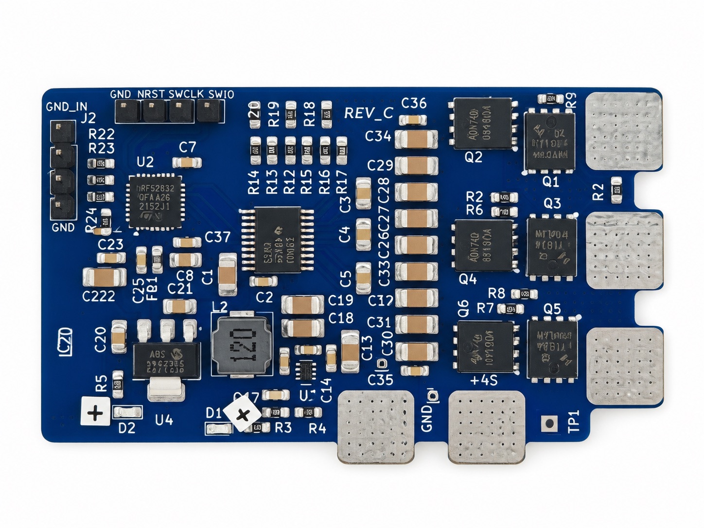
This image was edited using AI to remove stickers that were bloating the image.
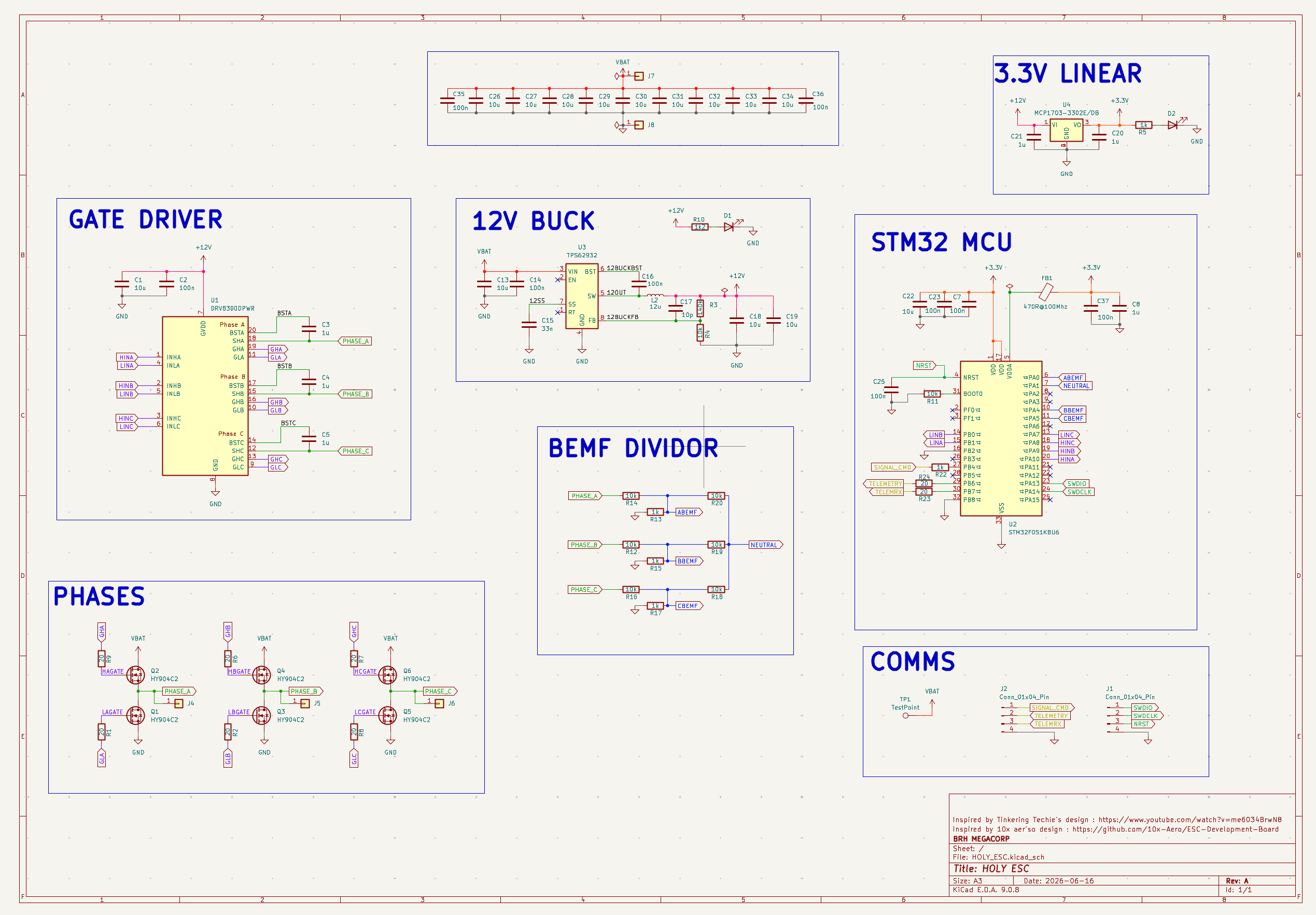
You can order the FULL BUILD in a couple of click right : (Todo : add link once project post is approved)
[!NOTE]
This ESC was featured in one of my youtube videos. You may be searching for the AtMega based firmware and perfboard BOM / Schematics. I did not put these here as the design worked but is not reliable. You can open an issue if you really want it and I'll add it to some "deprecated" folder in the repo.
The HOLY ESC is a BACK EMF based ESC, theorically able to be loaded up to 25Amps and more. But it serve educational purupses and has not be stress tested for any applications yet.
It was designed on KiCad 9 and aims at using cheap components to make the design accessible to all.
This design target drones and is planned to be tested on such applications soon.
Here are views of the PCB layers:
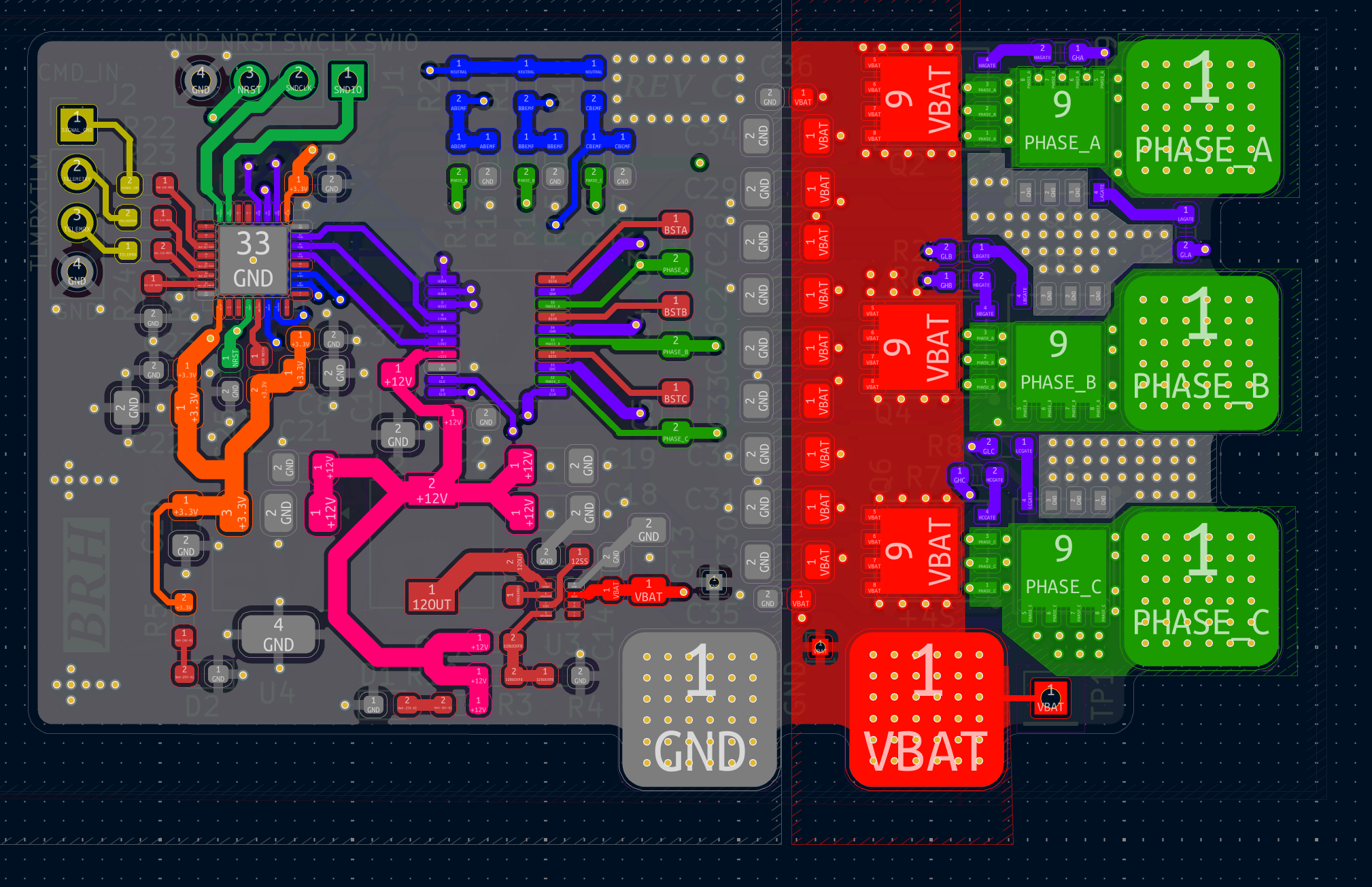
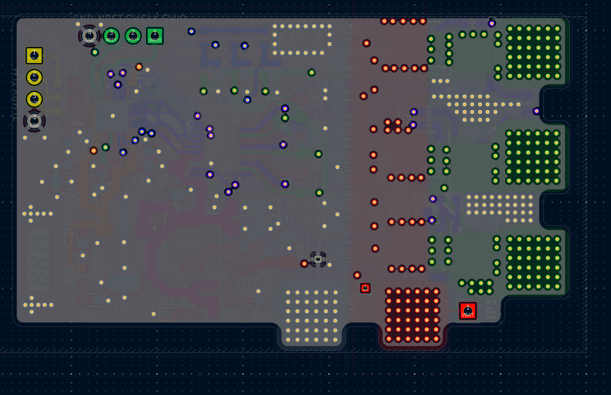
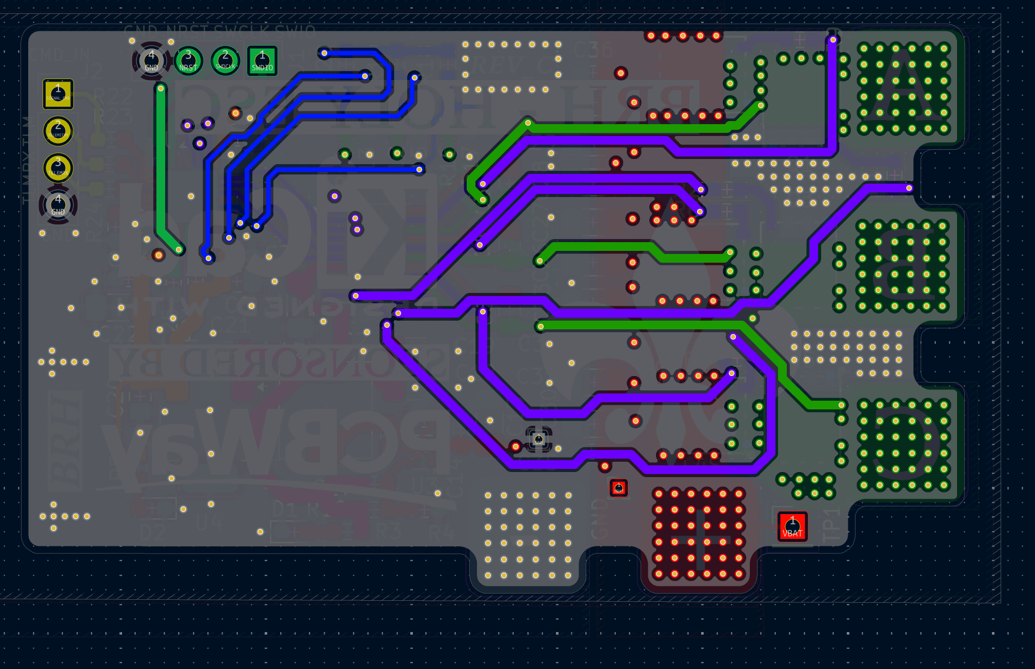
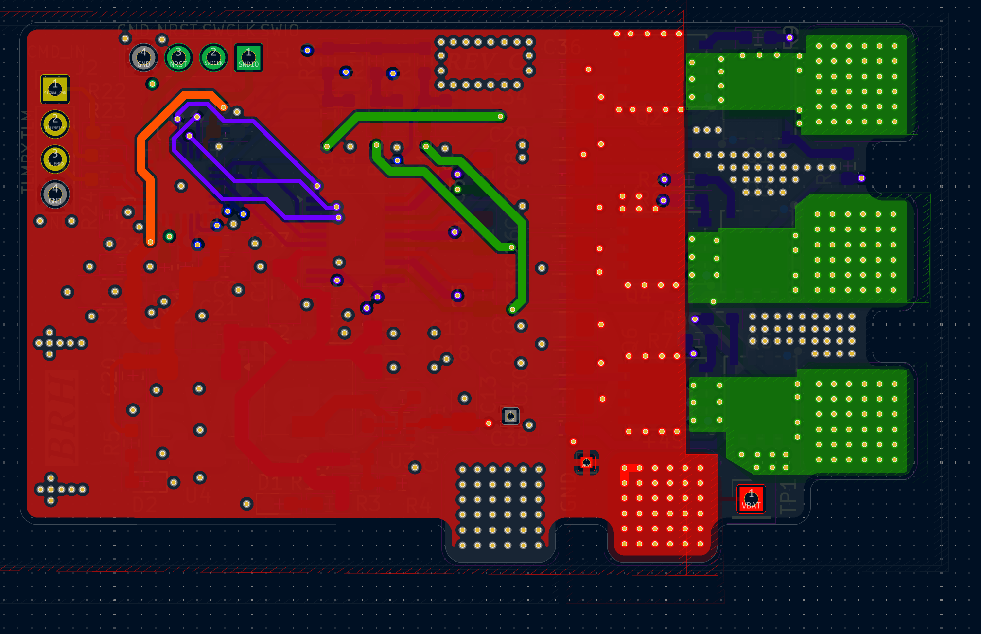
The hardware folder contains the KiCad9 files that you can open and modify as you like for your own needs, as long as you respect the project licence at the root of this repo.
The sofware part is a bit more tricky.
If you get the board manufactured, you will need to load a firmware on it. In this repo, I distribute AM32 binaries made specifically for this ESC.
Here is the procedure to start spinning a motor:
1. Connect the HOLY ESC to your host PC
First you'll need to connect the ESC's STM32 to a host computer.
So you'll need :
So connect the ESC to your power supply on the dedicated pads (Labeled "+" and "-" on the back of the PCB), I suggest limiting max current to 1 Amp in case a fault arises. Red LEDS should turn on, indicating a good supply of voltage into the board.
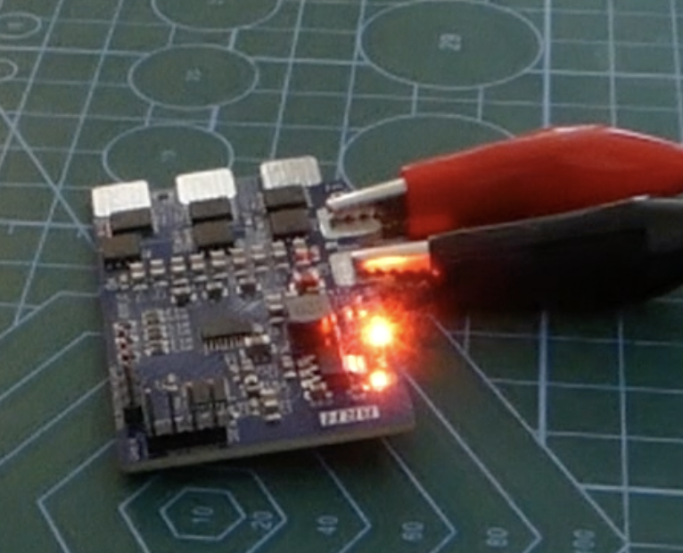
Connect the ESC SWD headers to you STLINK
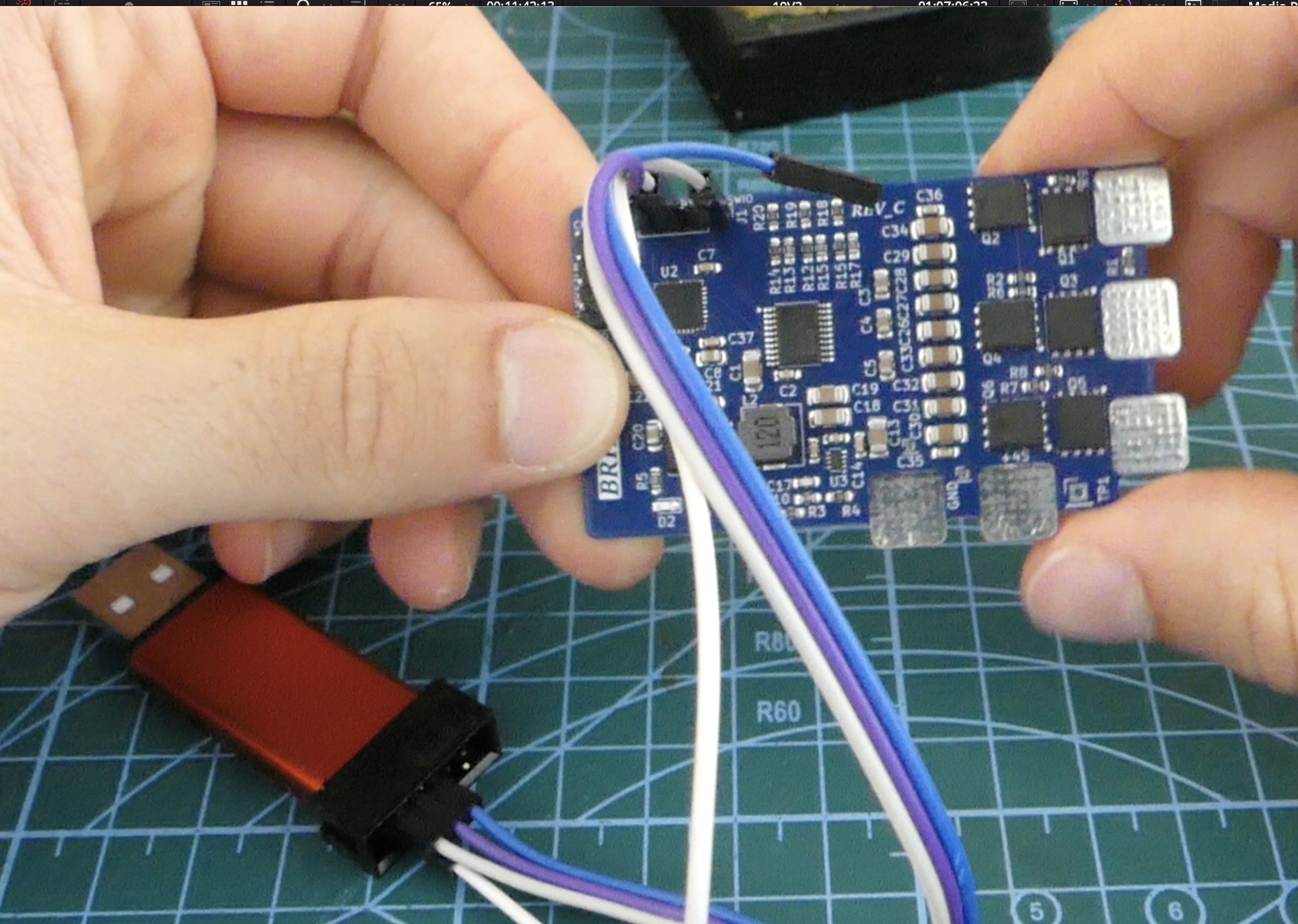
And plug it into you computer.
Launch STMCUBE Programmer, click connect and it should recognze the MCU on the ESC board.
At this point you can also connect a BLDC motor on the 3 phases pads using solder (labeled A; B & C on the back of the board).
2. Load the Firmware (EASY WAY)
Once everythoing is wired up correctly...
Use STM CUBE Programmer software (or st-flash fo cli) to prgogram the <repo>/software/holy_esc_firmware_am32.bin binary on the MCU (which is a STM32F051K8U6) @ base address 0x08000000.
This binary contains the AM32 build, along side the bootloading code and the eeprom.
2. Load the Firmware (DIY WAY)
If you decide to build the firmware from source to fit your need, asking a LLM to guide you through the AM32 targets.h modifs and from-source-building makes this process pretty easy.
Once you've got your build, you gotta flash it onto the MCU, alongside a bootloader and a eeprom data region.
The procedure to load these things is described there:
You can use STMCube's "Erasing and Programming" tab to select a binary and load it to a specified address. Just load each binary at the right address and you should be good to go.
To verify if you corecty modified a memory region, you can use the "Memory and File editing tab" to read a specific memory region, to check if it changed from the default values.
Bootloading and eeprom binaries are found in the page linked above. You will find the specific binary built for this specific board in ./software/
[!TIP]
If you are hardstuck on trying to lad a firmware, you can open an issue to get support.
Once the firmware is succesfully loaded, connect a BLDC motor to the phases pads (labeled A, B and C at the back of the PCB) using solder. Turn on your power supply (with STLINKV2 connected to PC or completely off the board to avoid asserting reset) and you should ear 3 beeps, indicating the motor is ready to armed !
Congratulations ! Now to spin a motor, you can use an arduino + voltage divider as a quick test, like I did in the video (use an LLM to write the arming sequence and speed command PWM generation) or use a servo tester / real flight controller.
[!INFO] Telemetry feedback and AM32 monitoring tools not tested yet
A big thank you to these actors, who were a great source of inspiration in my learning and designing process !
| Qty | Value | Footprint | References |
|---|---|---|---|
| 14 | 10u | Capacitor_SMD:C_1206_3216Metric_Pad1.33x1.80mm_HandSolder | C1, C13, C18, C19, C22, C26, C27, C28, C29, C30, C31, C32, C33, C34 |
| 9 | 100n | Capacitor_SMD:C_0603_1608Metric_Pad1.08x0.95mm_HandSolder | C2, C7, C14, C16, C23, C25, C35, C36, C37 |
| 8 | 10k | Resistor_SMD:R_0603_1608Metric_Pad0.98x0.95mm_HandSolder | R4, R11, R12, R14, R16, R18, R19, R20 |
| 8 | 20 | Resistor_SMD:R_0603_1608Metric_Pad0.98x0.95mm_HandSolder | R1, R2, R6, R7, R8, R9, R23, R24 |
| 6 | 1u | Capacitor_SMD:C_0805_2012Metric_Pad1.18x1.45mm_HandSolder | C3, C4, C5, C8, C20, C21 |
| 6 | HY904C2 | esc:DFN-8_L5.9-W5.2-P1.27-LS6.2-BL | Q1, Q2, Q3, Q4, Q5, Q6 |
| 5 | 1k | Resistor_SMD:R_0603_1608Metric_Pad0.98x0.95mm_HandSolder | R5, R13, R15, R17, R22 |
| 5 | ~ | esc:BatteryPad | J4, J5, J6, J7, J8 |
| 2 | Conn_01x04_Pin | Connector_PinHeader_2.54mm:PinHeader_1x04_P2.54mm_Vertical | J1, J2 |
| 2 | RED | LED_SMD:LED_0603_1608Metric_Pad1.05x0.95mm_HandSolder | D1, D2 |
| 1 | 10p | Capacitor_SMD:C_0603_1608Metric_Pad1.08x0.95mm_HandSolder | C17 |
| 1 | 12u | Inductor_SMD:L_6.3x6.3_H3 | L2 |
| 1 | 140k | Resistor_SMD:R_0603_1608Metric_Pad0.98x0.95mm_HandSolder | R3 |
| 1 | 1k2 | Resistor_SMD:R_0603_1608Metric_Pad0.98x0.95mm_HandSolder | R10 |
| 1 | 33n | Capacitor_SMD:C_0603_1608Metric_Pad1.08x0.95mm_HandSolder | C15 |
| 1 | 470R@100Mhz | Inductor_SMD:L_0603_1608Metric_Pad1.05x0.95mm_HandSolder | FB1 |
| 1 | DRV8300DPWR | Package_SO:TSSOP-20_4.4x6.5mm_P0.65mm | U1 |
| 1 | LOGO | esc:lys_small | G*** |
| 1 | LOGO | esc:kicad | G*** |
| 1 | LOGO | esc:pcbway_small | G*** |
| 1 | MCP1703-3302E/DB | Package_TO_SOT_SMD:SOT-223 | U4 |
| 1 | STM32F051K8U6 | Package_DFN_QFN:QFN-32-1EP_5x5mm_P0.5mm_EP3.45x3.45mm | U2 |
| 1 | TPS62932 | Package_TO_SOT_SMD:SOT-583-8 | U3 |
| 1 | TestPoint | Connector_PinHeader_2.54mm:PinHeader_1x01_P2.54mm_Vertical | TP1 |
The 79 most common of 81 parts.

10x-Aero/ESC-Development-Board
A 6S AM32-compatible ESC built as a proof of concept for learning how to design an ESC from scratch

Zergie/YAMMU
A Multi Material Unit (MMU) for eight filaments that can also function as a filament dryer and can keep it dry while printing. The design is heavily inspired by voron and their printers.


KungfuPancake/longboi
Possibly the longest controller board to control the BoxTurtle AFC

WRansohoff/STEAMGal_Tetris
Try writing some 'tetris' firmware for a development board with a very small display, a buzzer, and a few buttons. That should introduce a few core peripherals.


JacobParent7/FSAE_LSU_BMS
Distributed BMS designed for FSAE around the STM32 microcontroller and BQ79616/BQ79614/BQ79612 precision battery monitor, balancer and integrated protector.
It measures 64.9 × 39.2 mm and has 4 copper layers, 1.6 mm thick.
81 parts, built around the STM32F051K8U6, DRV8300DPWR-MS, TPS62932DRL and MCP1703-3302E/DB. The full list of its parts is on this page, with links to each part's symbol and footprint where PCBKit's library has them.
From the 0BAB1/HOLY_ESC repository on GitHub, at the commit this page was made from: the board is hardware/ESC_PCB_REVC/HOLY_ESC.kicad_pcb and its schematic hardware/ESC_PCB_REVC/HOLY_ESC.kicad_sch. PCBKit opens the board in the browser, with nothing to install.
Its repository states no licence, so its author keeps all rights: ask 0BAB1 before reusing the design.