2 layers104.1 × 54.6 mm

 yvoronkin/FANSTOP2
In a small form factor, an extension of the fan control is implemented.
PWM+fan stop is an open-source printed circuit board by yvoronkin, from the yvoronkin/FANSTOP repository on GitHub, published under the CERN-OHL-S-2.0 licence. It is a 2-layer board of 24.6 × 11.1 mm with 24 parts on 13 nets, routed with 153 tracks and 33 vias.
It is built around the ATTINY10-TSH, L78L05ABUTR and AO3413. Its parts include 6 resistors, 3 capacitors, 2 ICs, 2 diodes and 2 transistors. It belongs with the AVR (ATmega, ATtiny) boards of this library.


An inline hardware adapter that adds true fan stop to 4-wire PWM fans and supply-PWM control to 2- and 3-wire fans.
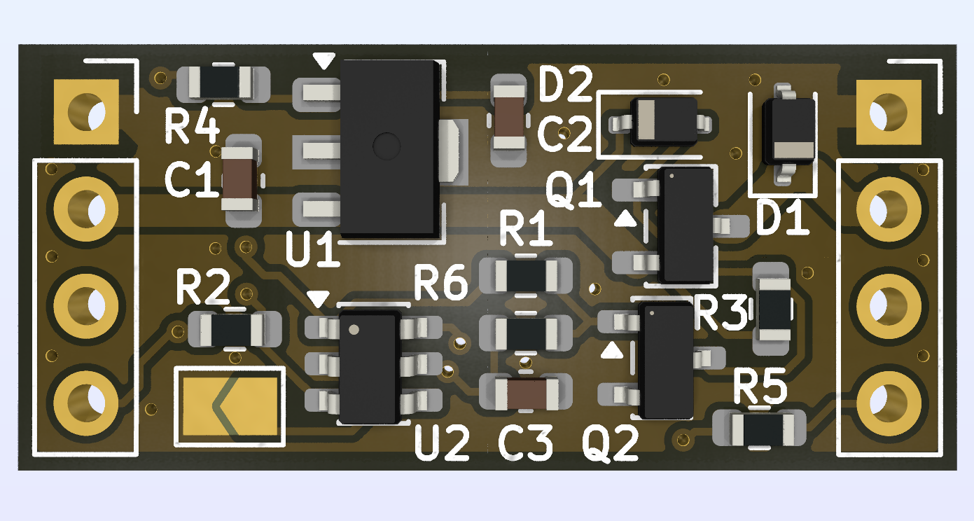
Some fans keep spinning even when their controller outputs 0% duty cycle. Other fans expose only power and tachometer pins, so they cannot use the standard 4-wire PWM control input at all.
FANSTOP sits between a 12V fan controller and a fan. An ATtiny10 measures the incoming PWM signal and controls a high-side MOSFET in one of two selectable operating modes.
[!CAUTION] FANSTOP can remove power from a cooling fan. Validate the module, firmware thresholds, fan startup behavior, and thermal protection before using it on equipment that can be damaged by loss of cooling.
Mode is sampled at startup using solder jumper JP1
| JP1 | Mode | Output behavior |
|---|---|---|
| Open | 4-wire fan-stop | PWM and tachometer pass through. The module switches the fan's 12 V supply only when fan-stop is requested. |
| Bridged | 2/3-wire supply PWM | Incomming PWM duty is reproduced by switching the fan's 12V supply at a lower frequency. Tachometer passes through. |
This is the default mode.
| Input state | Result |
|---|---|
| Duty cycle below 5% for approximately 300 ms | Fan supply OFF |
| Duty cycle from 5% through 10 % | Keep the previous ON/OFF state |
| Duty cycle abowe 10% | Fan supply ON |
| Static LOW | Treated as a stop request after the debounce interval |
| Static HIGH | Fan supply ON |
The firmware accepts PWM periods from 240 to 500 timer ticks. At the 8 MHz MCU clock this corresponds to approximately 16-33.3 kHz, covering the nominal 25 kHz 4-wire PC-fan control signal.
Bridge JP1 before powering the board. FANSTOP measures the incoming duty cycle and generates power PWM through the high-side MOSFET.
The output timing is derived from the measured input:
output frequency = input frequency / 100
For a nominal 25 kHz input, the fan supply is therefore switched at approximately 250 Hz. The tachometer line remains connected directly between input and output.
Because the entire fan supply is switched, fan compatibility, acoustic noise, tathometer quality, and reliable startup at low duty cycles depends on the particular fan.
Both fan connectors use the standard 4-wire PC-fan pin order:
| Pin | Signal | Notes |
|---|---|---|
| 1 | GND | Common ground |
| 2 | +12V | Fan supply; switched on the output side |
| 3 | Tach | Passed through directly |
| 4 | PWM | Control input and hardware pass-through |
Connect the controller or motherboard to PWM_IN (J1) and the fan to PWM_OUT (J2). Do not reverse the board direction or connector polarity.
The PWM input is pulled up to 5V on the module and is intended for the usual open-collector/open-drain fan-control interface. Verify compatibility before connecting a push-pull controller.
L78L05 regulator)A03413 P-channel MOSFET driven through a 2N7002The 2 A figure is a layout target, not a certified continuous-current rating. The practical limit also depends on connectors, assembly quality, ambient temperature, MOSFET dissipation, and fan startup current.
The firmware is a PlatformIO project and uses a pinned AVR toolchain that contains ATtiny10 support
git clone https://github.com/yvoronkin/FANSTOP.git
cd FANSTOP/firmware
pio run
The resulting firmware image is placed under:
.pio/build/attiny10/firmware.hex
ATtiny10 uses the TPI programming interface. The board exposes five programming pads:
| Pad | Signal |
|---|---|
| GND | Ground |
| +5V | Programming supply |
| DAT | TPI data |
| RST | Reset |
| CLK | TPI clock |
The tools/ directory contains a printable programming gixture in FreeCAD and STL formats.
FANSTOP is an actively developed hardware project. The firmware builds with PlatformIO, but fan controllers and fans vary considerably; treat electrical, thermal, acoustic, and tachometer compatibility as something to validate for each installation.
Bug reports, oscilloscope captures, fan compatibility results, firmware improvements, and hardware revisions are welcome. When reporting a control issue, include the fan model, input PWM frequency and duty cycle, selected mode, and measured output behavior.
| Qty | Value | Footprint | References |
|---|---|---|---|
| 2 | 10k | Resistor_SMD:R_0603_1608Metric | R3, R4 |
| 2 | 1k | Resistor_SMD:R_0603_1608Metric | R1, R2 |
| 2 | 1uF | Capacitor_SMD:C_0603_1608Metric | C1, C2 |
| 2 | GND | TestPoint:TestPoint_Pad_D1.5mm | TP1, TP6 |
| 1 | +5V | TestPoint:TestPoint_Pad_D1.5mm | TP2 |
| 1 | 100k | Resistor_SMD:R_0603_1608Metric | R6 |
| 1 | 100nF | Capacitor_SMD:C_0603_1608Metric | C3 |
| 1 | 2.2k | Resistor_SMD:R_0603_1608Metric | R5 |
| 1 | 2N7002 | Package_TO_SOT_SMD:SOT-23 | Q2 |
| 1 | AO3413 | Package_TO_SOT_SMD:SOT-23-3 | Q1 |
| 1 | ATtiny10-TS | Package_TO_SOT_SMD:SOT-23-6 | U2 |
| 1 | BZX384-B6V2.115 | Diode_SMD:D_SOD-323 | D2 |
| 1 | CLK | TestPoint:TestPoint_Pad_D1.5mm | TP5 |
| 1 | CONF1 | Jumper:SolderJumper-2_P1.3mm_Open_TrianglePad1.0x1.5mm | JP1 |
| 1 | DAT | TestPoint:TestPoint_Pad_D1.5mm | TP3 |
| 1 | L78L05ABUTR | Package_TO_SOT_SMD:SOT-89-3 | U1 |
| 1 | PWM_IN | Connector_PinSocket_2.54mm:PinSocket_1x04_P2.54mm_Vertical | J1 |
| 1 | PWM_OUT | Connector_PinSocket_2.54mm:PinSocket_1x04_P2.54mm_Vertical | J2 |
| 1 | RST | TestPoint:TestPoint_Pad_D1.5mm | TP4 |
| 1 | TVS VRWM15 | Diode_SMD:D_SOD-323 | D1 |
It measures 24.6 × 11.1 mm and has 2 copper layers, 1.6 mm thick.
24 parts, built around the ATTINY10-TSH, L78L05ABUTR and AO3413. The full list of its parts is on this page, with links to each part's symbol and footprint where PCBKit's library has them.
From the yvoronkin/FANSTOP repository on GitHub, at the commit this page was made from: the board is hardware/PWM+fan_stop.kicad_pcb and its schematic hardware/PWM+fan_stop.kicad_sch. PCBKit opens the board in the browser, with nothing to install.
Its repository publishes it under the CERN-OHL-S-2.0 licence: you may reuse it on that licence's terms (keep the author's notice, and for a copyleft licence share your changes alike).

Diabltica/AudioInterface
An hardware audio interface featuring an ouput selector and an amplifier powered by usb C


calcpsu/cphp82001
CalcPack replacement for HP 82001, suits HP35/45/55/65/67 calculators


