Skip to the content
PCBKitNew board
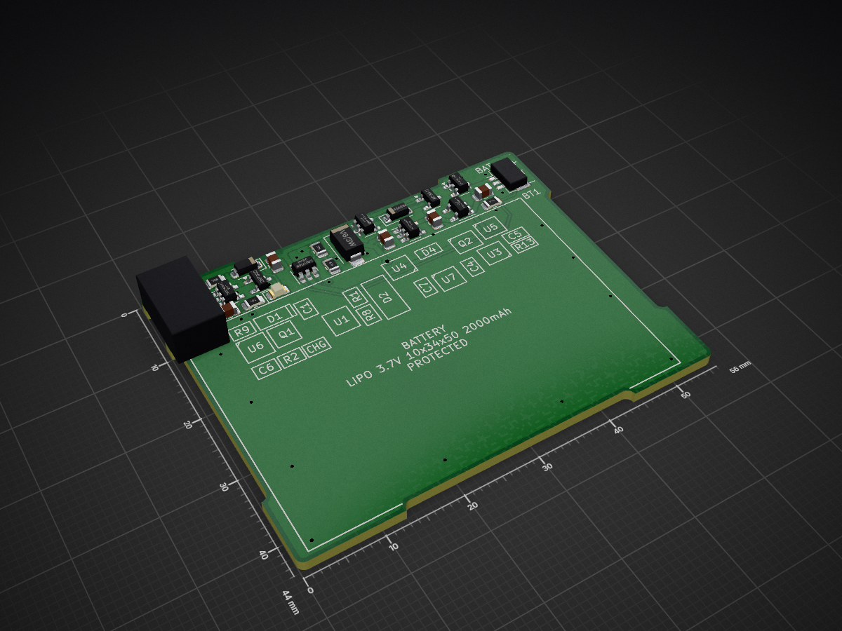
2 layers56 × 44 mmCphp82001-pcb, the printed circuit board in 3D

Cphp82001-pcb

calcpsu/cphp820014

CalcPack replacement for HP 82001, suits HP35/45/55/65/67 calculators

Size
56 × 44 mm
Copper layers
2
Thickness
1.6 mm
Parts
30
Nets
21
Pads
81
Tracks, vias
79, 29
Pours
3
Routed
Yes
KiCad
KiCad 8.0 (file 20240108)
Created
9 Jan 2024
Updated
19 Feb 2025

Overview

Cphp82001-pcb is an open-source printed circuit board by calcpsu, from the calcpsu/cphp82001 repository on GitHub. It is a 2-layer board of 56 × 44 mm with 30 parts on 21 nets, routed with 79 tracks and 29 vias.

It is built around the APX809S-31SA, APX810-44SAG and BQ21040DBV, with the MAX40203AUK+T, 1N4148W and AO3413 among its other parts. Its parts include 6 ICs, 5 capacitors, 5 resistors, 4 diodes and 3 connectors.

Main components

7

README

README.md

CalcPack HP 82001

A Li-Po battery replacement design for HP35/HP45/HP55/HP65/HP67 calculators. The original batteries had ~ 500mAh capacity, while modern Ni-MH replacements are typically ~1500mAh.

Li-Po has the advantage of far reduced self-discharge in comparison to Ni-MH, which is an advantage for an intermittently-used device. Even with similar mAh capacity, we can expect longer battery life.

Ni-MH / Ni-CD batteries are notorious for leaking. While Lithium Ion batteries are notorious for self-immolation, a well protected Li-Po battery (particularly in a low current application like this) should be able to be made very safe.

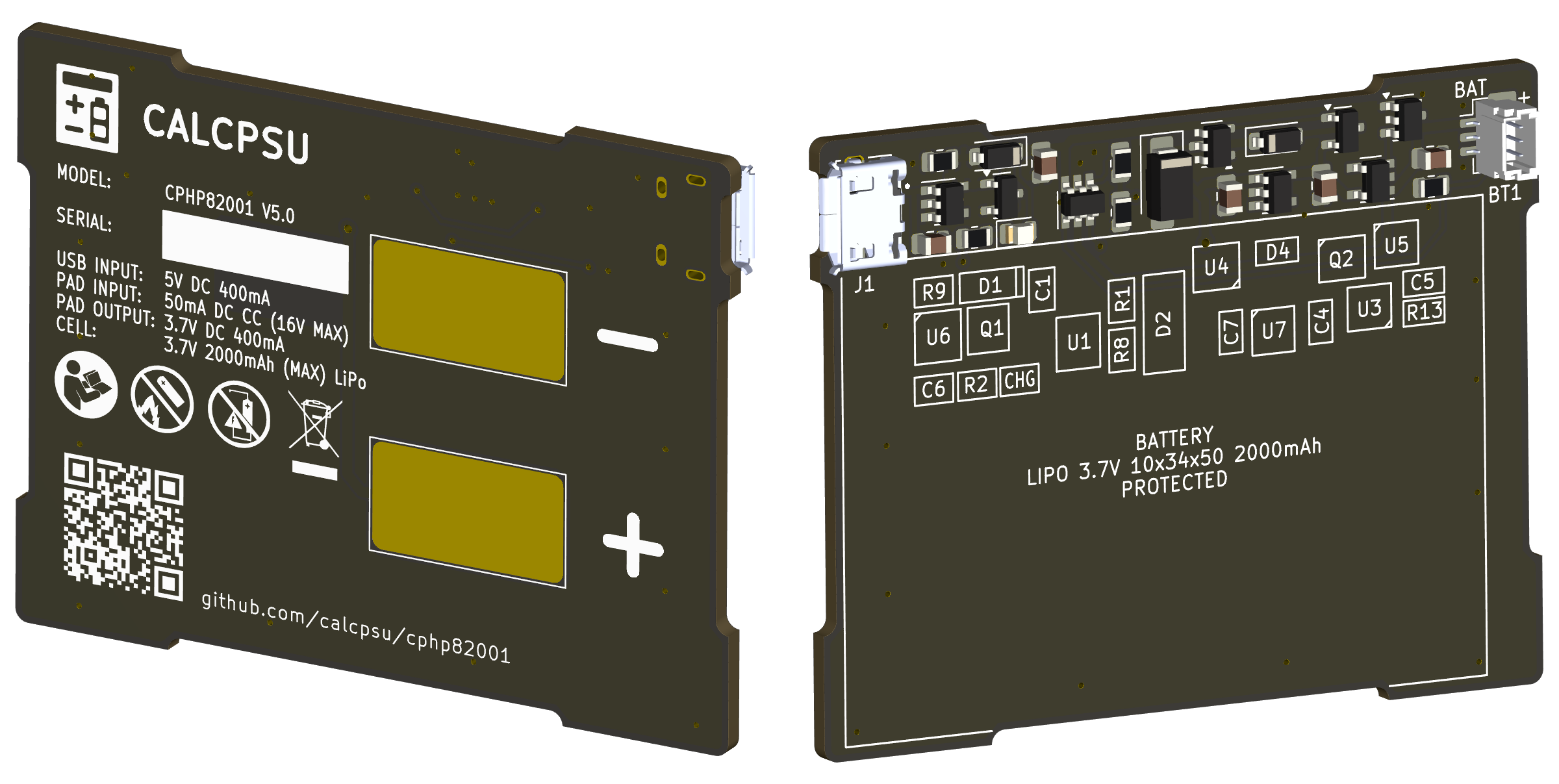
Render of calcpack PCB

Features / design goals:

  • Fit into existing compartment with no modifications
  • Similar or ideally exceed capacity of standard Ni-Cd or Ni-MH 3xAA types (1200~2200mAh)
  • Dual charge - USB (externally) or in-place using original HP charger
  • Battery charge control and protection
  • Maximise battery life:
    • Minimise Iq to maximise time between charges (shelf time)
    • Minimise voltage drop / series resistance of circuits to maximise run time
    • Optimise Vout to minimise calculator power consumption

References

This has been inspired by the below reference projects:

Key Components

If you're looking for a full BOM, please check the main files. A digikey list is provided here for convenience (no guarantees!): calcpsu cphp82001

  • Battery:
    • 10x34x50mm lipo pouch cell. These also include a DW01A/FS8205 protection circuit.
  • Charge controller: BQ21040
    • Wide voltage input range (over voltage protected)
    • Clever voltage foldback mode (which will help with constant current supply charging)
    • Variable current setting
    • Safety timer (10h) and 10% termination current
  • OPTION 1: Regulator: TLV75801
    • Ultra low dropout (~30mV)
    • 500mA current limited (enough for HP67 card read/write at ~400mA for a few seconds)
    • Very low Iq for a regulator (25uA at idle, assuming Vb > Vo; only 400uA or so at full current)
    • Note: option eliminated as of REV5; if you're really keen for a regulated version please to check out rev4.
  • OPTION 2: Current Limiter: MCP380SNT
    • Designed as a USB input current limiter, also works for LiPo cell voltage range
    • 800mA limiting, short circuit protection
    • Provides the similar current limiting capability as the TLV75801 with minimal additional quiescent current; allows retaining this function/protection in case of an unregulated option.
  • Output protection diode: MAX40203
    • Low voltage drop (~40mV) ideal diode
    • Low leakage and low Iq (<0.5uA)
  • Undervoltage protection: APX809S-31SA
    • Pre-set with 3.1V threshold
    • Output used to shutdown regulator, shutting off load and vastly reducing Iq
    • Actual protective disconnection of battery done at ~2.5V by battery pack protection circuit (typically DW01A/FS8205)
  • Input overvoltage protection: NCP360SNT
    • Cuts off USB input for overvoltage condition (note that 2x rated voltage is required by compliance test standard EN38.3 T.7, required for transport of lipo batteries in USA/EU).
    • Input via pads does not require OVP - it can tolerate the required 22v/100mA required condition.

Function Description

Block diagram of battery

Discharging, calculator on:

  • B+ supplies cell voltage via current limiting IC
  • Output delivered to calculator via ideal diode U3
  • Vout at 3.8V is below threshold for U4 (4.4V), Q2 is off and VCC is 0V (charging IC shutdown completely)

Charging, USB:

  • VBUS supplies VCC via U6 and D1
  • Presence of VBUS pulls prog down via Q1, charge controller now charges battery at higher current (0.2C target)
  • Physically not possible to do inside the calculator, can assume calculator is not connected during charging.
    • Although, body diode of Q2 and U3 would enable effective load sharing in this case, with output at about 4V (still well within acceptable limits for the calculator). This could be used for a future alternative in-system charging connection (e.g. a modified charging circuit, wireless charging, etc.)

Charging, HP charger:

  • HP charger supplies 50mA constant current, up to 16V (!!). With the original NiCads, these acted as a voltage clamp (float charge about 1.43V/cell = 4.3V) - we need to replace this function.
    • With no charging current, voltage Vout rises until U3 switches off.
    • Will continue to rise until clamped by D2 (this should be low enough to protect HP65/67 sense chip from harm with extended application, but too low will result in excessive Iq as the voltage nears the zener's knee). Reviewing available documents, 4.3V is definitely OK, 6.25V might be survivable (as this is Vss normally). I have tested with 5.6V zener, and this has shown no negative impact to any calculators (particualrly the HP-67, where the sense chip sees this voltage, albeit when off).
    • Exceeding 4.4V for 240ms, U4 activates and connects Vout to Vcc via Q2 and D4.
    • D4 ensures that U1 throttles current (Vcc below 4.3V) before U4 cuts off supply (VOUTF 4.4V), maximising utilisation of limited constant current supply. See further explanation in issue #5.
    • U1 begins charge cycle, delivering up to 50mA to battery.
    • On charge termination, VCC current is minimal (10's of uA), all 50mA will be running through D2 (~0.25W power; using biggest one I can fit to keep temperature down). Voltage will be at the zener voltage (5.6V).
  • HP35/45/55 calculators do not draw current when on - supplied separately by HP AC adapter, the calculator supply is physically disconnected from the charging circuit.
  • HP65/67 with card reader: card reader may draw from battery supply. The sense chip is connected to the battery continuously, and will see up to the 5.6V float voltage. In case the calculator is operated and this draws current, the CC supply voltage will drop until U4 shuts off current to the charge circuit, resetting the charge cycle. When VOUT drops below B+, U3 activates, and card reader is powered from the current limiter (B+). As the AC adapter is not sufficient to run the card reader, this is the least worst outcome available.

Battery Exhausted:

  • HP35 shows low battery (decimal points) indication at V+ of 3.50V.
    • This represents about 6-7% charge state of LiPo
    • User may switch off and recharge now...
  • HP67 will show indicator at about 3.60V; similar to above but a little more margin.
  • HP35 will cease to function at ~3.25V, still draws ~75mA
    • User probably should switch off and recharge now...
  • U4 protects battery at VB+ = 3.1V, by disabling the regulator or current limiting IC. Iq should be ~10uA.
  • If left for a really long time, VB+ may reduce to 2.5V, which should trigger battery pack protection circuit and fully disconnect the battery. Plugging in (turning on charge controller, which will do a battery detection routine and reset the protection circuit) will reset.

Assembly Notes

Refer to the schematic for details. The following notes are worth considering if building your own:

  • The design up to v4 allows either regulated or unregulated option. From v5, only unregulated is supported (and recommended, see below).
    • For regulated (best for HP35), U2 regulator provides regulation and current limiting - U7 is not required and can be omitted and bypassed.
    • For unregulated (best for all later types), U2 is omitted and bypassed, and U7 is added to provide current limiting
  • Digikey list is here
  • A 3-pin JST-SH (1.0mm pitch) connector is used for the battery. 1=pos, 2=temp, 3=neg
    • R13 is in parallel with TS pin NTC thermistor. If the battery does not a provide NTC thermistor (white wire, 3 pin connector), leave pin2 open and install R13=10k.
    • Note datasheet indicates 237k resistor prevents timer disable mode, but this also prevents charging without thermistor
R13Battery With Temperature SensorBattery Without Temperature Sensor
Omit🟢 10% Current Charge Termination
🟢 10h Charge Timeout
🔴 10% Current Charge Termination
🔴 10h Charge Timeout
10k⚠️ Will not charge T>25C
⚠️ Will charge T<0C
🟢 10% Current Charge Termination
🟢 charge timeout
  • Two case sizes are provided:
    • 8mm suits 8mm thick batteries (1500mAh)
    • 10mm suits 10mm thick batteries (2000mAh), but it has been noted this can be a tight fit in some calculators
  • Variants of each case, with and without an LED hole, are provided. If you 3D print with a transluscent material, the hole is not needed!

Notes on optimisation:

Addition of a series regulator is not an immediately obvious means to maximise efficiency. I've measured the HP-35 increases current consumption as voltage rises (this is most likely a result of the way the LEDs are driven with fixed-duty inductive energy, this appears as brighter leds). Even accounting for the linear loss and Iq of the regulator circuit, total power consumption decreases as the regulator voltage decreases (down to about 3.6V, the minimum to operate the calculator reliably). The newer models (HP-45, HP-67) do the opposite - the current drops as the voltage increases, which indicates a more typical profile for a switchmode converter. The HP-67 has a card reader with a motor; this draws around 400mA when reading/writing a card, direct from battery. To allow for a little drop in the system, the regulator voltage needs to be a touch higher (looks like about 3.8V works consistently).

Why not a switching regulator?

In theory, replacing the series linear regulator with a switching regulator may allow use of the battery capacity right down to 3.1V, and more efficiently use the currently wasted energy of the full battery (VB+ > 3.78V) currently being dissipated by the linear reg.

I've investigated using a MIC2250 step-up regulator, which has a surprisingly low Iq (55uA, not switching), and could provide a consistent output voltage right down to the end of the battery capacity (Vb=3.0V). At the currents needed, this can be around 87% efficient. This would provide a consistent voltage right up until shutdown. While this might be good particularly for the HP-67 card reader, it has the disadvantage of skipping the calculator's built-in low battery indication - the power supply unit would completely shutdown without any warning with a low battery.

Model of 3 options

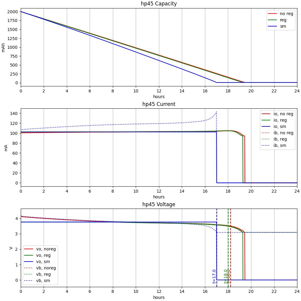
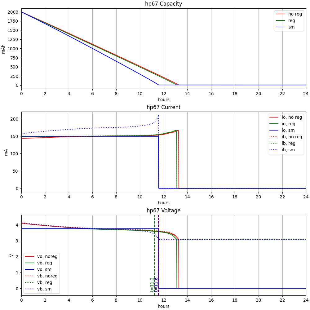
I've done a simulation of the 3 options:

  1. No regulator (default - calculator supplied with battery voltage via MAX40203 diode)
  2. Linear regulator (TLV75801, set to 3.80V)
  3. Switchmode step-up regulator (MIC2250, set to 3.80V also)

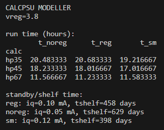
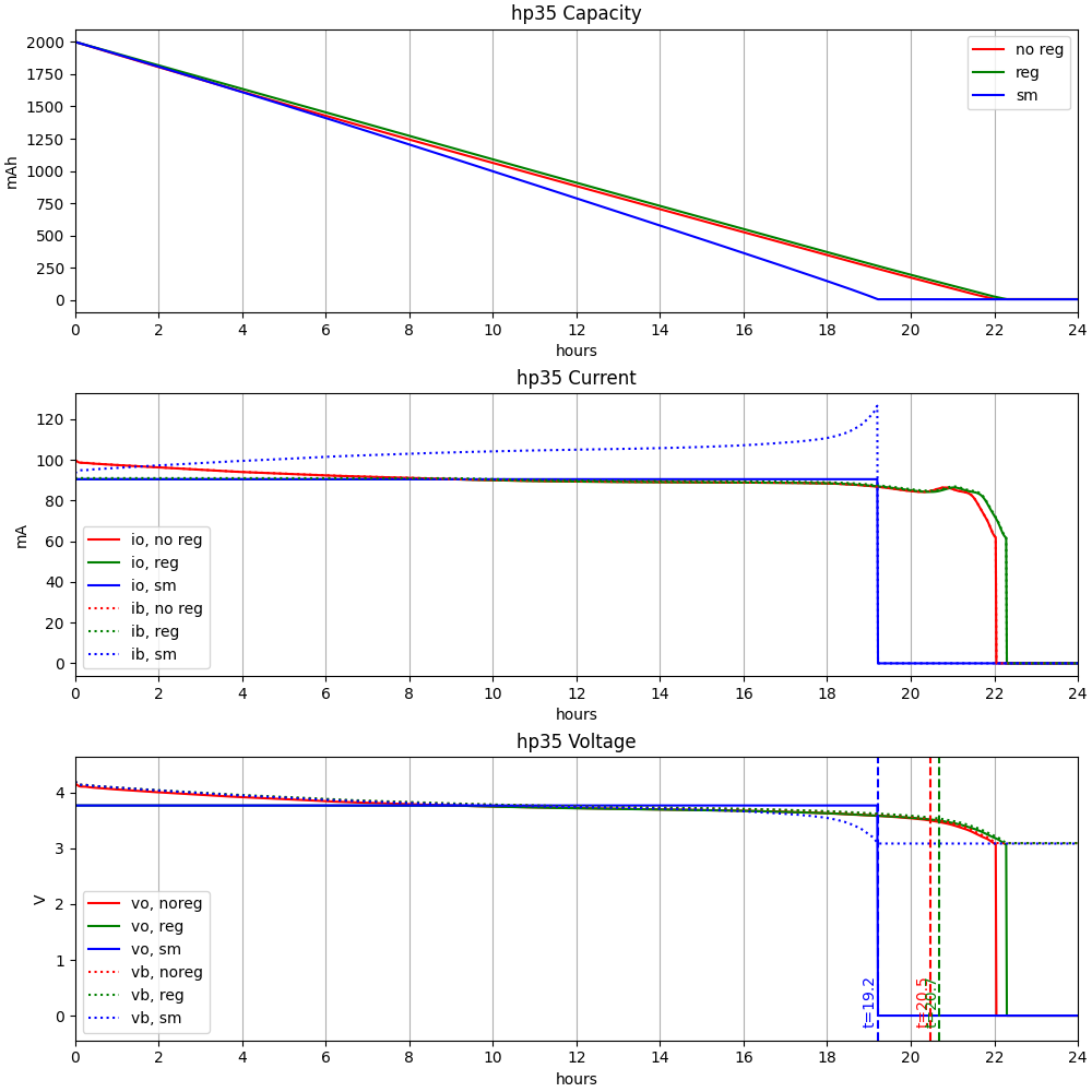
For each, the model calculates the change in output voltages given the battery state, calculator and power supply current draw, and iterates until the battery (2000mAh) is exhausted. The calculator load is measured from 3 sample calculators (HP-35, HP-45 and HP-67), reflecting the calculator being left on in the default display ("0." or "0.00" depending on the model), and accounts for the changing current with changing supply voltage. Results are shown below.

In summary, a regulated design gains a slight advantage in run time for the HP-35, while slightly reducing run time for HP-45 and HP-67. The switchmode design is actually best for the current-hungry HP-67, but not by a significant amount, and at the cost of higher quiescent current (shortening standby time significantly).

In conclusion, the regulated design provides a slight advantage for the HP-35 based on this model, however the unregulated design (with addition of necessary output short-circuit protection / current limiter) can be expected to be ideal for other models. Prototype testing with rev 3.5 showed the unregulated design works well in all the calculators, and the regulated design had noticeably faster self-discharge in practice, particularly as the quiescent current is larger than anticipated in dropout mode. As such, further designs have eliminated the regulator in favour of improved board layout and ease of use.

Results summary (t in hours)

Image of power model results

HP-35

Image of power model results

HP-45

Image of power model results

HP-67

Image of power model results

Community Builds

Built one? Send me some pics and I'll share here!

Milo van der Zee

Photo of build by Milo van der Zee

License

This work is licensed under a Creative Commons Attribution-NonCommercial-ShareAlike 4.0 International License.

CC BY-NC-SA 4.0

Parts

30
QtyValueFootprintReferences
31uCapacitor_SMD:C_0805_2012MetricC1, C4, C6
2LOGOLOGOG***, G***
110kResistor_SMD:R_0805_2012MetricR13
110uCapacitor_SMD:C_0805_2012MetricC7
11N4148WDiode_SMD:D_SOD-123D4
11k8Resistor_SMD:R_0805_2012MetricR1
12N7002Package_TO_SOT_SMD:SOT-23Q1
133kResistor_SMD:R_0805_2012MetricR9
13kResistor_SMD:R_0805_2012MetricR2
14u7Capacitor_SMD:C_0805_2012MetricC5
15V6/3WDiode_SMD:D_SMAD2
19k1Resistor_SMD:R_0805_2012MetricR8
1AO3413Package_TO_SOT_SMD:SOT-23Q2
1APX809S-31SAPackage_TO_SOT_SMD:SOT-23-3U5
1APX810-44SAPackage_TO_SOT_SMD:SOT-23-3U4
1BQ21040george:SOT-23-6_TI_DBV6U1
1Battgeorge:JST_SH_BM03B-SRSS-TB_1x03-1MP_P1.00mm_Vertical_13PADSBT1
1MAX40203AUKgeorge:SOT-23-5_TI_DBV5U3
1NCP360SNTgeorge:SOT-23-5_TI_DBV5U6
1NCP380HSN05george:SOT-23-5_TI_DBV5U7
1PAD+george:PAD_8x15J2
1PAD-george:PAD_8x15J3
1PMEG40T10ERXDiode_SMD:D_SOD-123D1
1REDLED_SMD:LED_0805_2012MetricD3
1USBmod_local:AMPHENOL_10118194-0001LFJ1

The 28 most common of 30 parts.

Questions

How big is the Cphp82001-pcb PCB?

It measures 56 × 44 mm and has 2 copper layers, 1.6 mm thick.

What parts does the Cphp82001-pcb use?

30 parts, built around the APX809S-31SA, APX810-44SAG, BQ21040DBV and MAX40203AUK+T. The full list of its parts is on this page, with links to each part's symbol and footprint where PCBKit's library has them.

Where can I download the Cphp82001-pcb KiCad files?

From the calcpsu/cphp82001 repository on GitHub, at the commit this page was made from: the board is cphp82001-pcb/cphp82001-pcb.kicad_pcb and its schematic cphp82001-pcb/cphp82001-pcb.kicad_sch. PCBKit opens the board in the browser, with nothing to install.

Can I use the Cphp82001-pcb design in my own project?

Its repository states no licence, so its author keeps all rights: ask calcpsu before reusing the design.

Similar boards

  • 2 layers51.4 × 43 mmCptibp8-pcb, the printed circuit board in 3D

    Cptibp8-pcb

    calcpsu/cptibp8

    CalcPack for TI BP8

    62 parts
  • 4 layers45.2 × 59.9 mmPcb quadrotor, the printed circuit board in 3D

    Pcb quadrotor

    AutopilotPi/V3s_Quadrotor

    A Quadrotor Using AutoPilotPi

    85 parts10GPL-3.0
  • 2 layers24.6 × 11.1 mmPWM+fan stop, the printed circuit board in 3D

    PWM+fan stop

    yvoronkin/FANSTOP

    In a small form factor, an extension of the fan control is implemented.

    24 parts2CERN-OHL-S-2.0
  • 2 layers100 × 100 mmPowersavers, the printed circuit board in 3D

    Powersavers

    Bolukan/KiCAD

    KiCad projects

    344 parts1MIT
  • 4 layers96 × 136 mmUSB C PD x2, the printed circuit board in 3D

    USB C PD x2

    Tuskar-Marine/hardware

    All tools for the Mermaid's Rest open sailing tools

    161 parts6
  • 2 layers38.1 × 19.6 mmDisplay oled, the printed circuit board in 3D

    Display oled

    joelspadin/marten_numpad

    Bluetooth numpad based on the nRF52840 SoC

    4 parts2
  • 4 layers50 × 50 mmRosmo ESC, the printed circuit board in 3D

    Rosmo ESC

    kitspace-test-repos/kicad6-file-collection

    116 partsMIT