2 layers56 × 44 mm
Cphp82001-pcb
calcpsu/cphp82001
CalcPack replacement for HP 82001, suits HP35/45/55/65/67 calculators
30 parts4

 calcpsu/cptibp8
CalcPack for TI BP8
Cptibp8-pcb is an open-source printed circuit board by calcpsu, from the calcpsu/cptibp8 repository on GitHub. It is a 2-layer board of 51.4 × 43 mm with 62 parts on 30 nets, routed with 171 tracks and 52 vias.
It is built around the AP63200WU, MIC2250-1YD5-TR and APX809S-31SA, with the BQ21040DBV, PMEG40T10ERX and AO3413 among its other parts. Its parts include 13 resistors, 12 capacitors, 7 diodes, 6 ICs and 6 connectors.


A Li-Po battery replacement design for TI BP7/8/9 battery pack calculators - e.g. TI-55, TI-30, TI Programmer, etc. The original batteries had ~ 500mAh capacity (@2.4V: 1.2Wh), while a typical 9V alkaline battery substitution as ~500mAh (@9V: 4.5Wh), albeit single-use only.
Li-Po has the advantage of far reduced self-discharge in comparison to Ni-Cd, which is an advantage for an intermittently-used device. Even with similar mAh capacity, we can expect longer battery life.
Ni-CD batteries are notorious for leaking. While Lithium Ion batteries are notorious for self-immolation, a well protected Li-Po battery (particularly in a low current application like this) should be able to be made very safe.
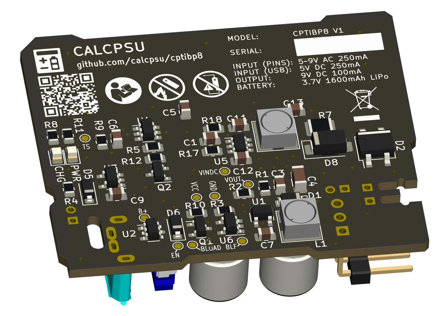
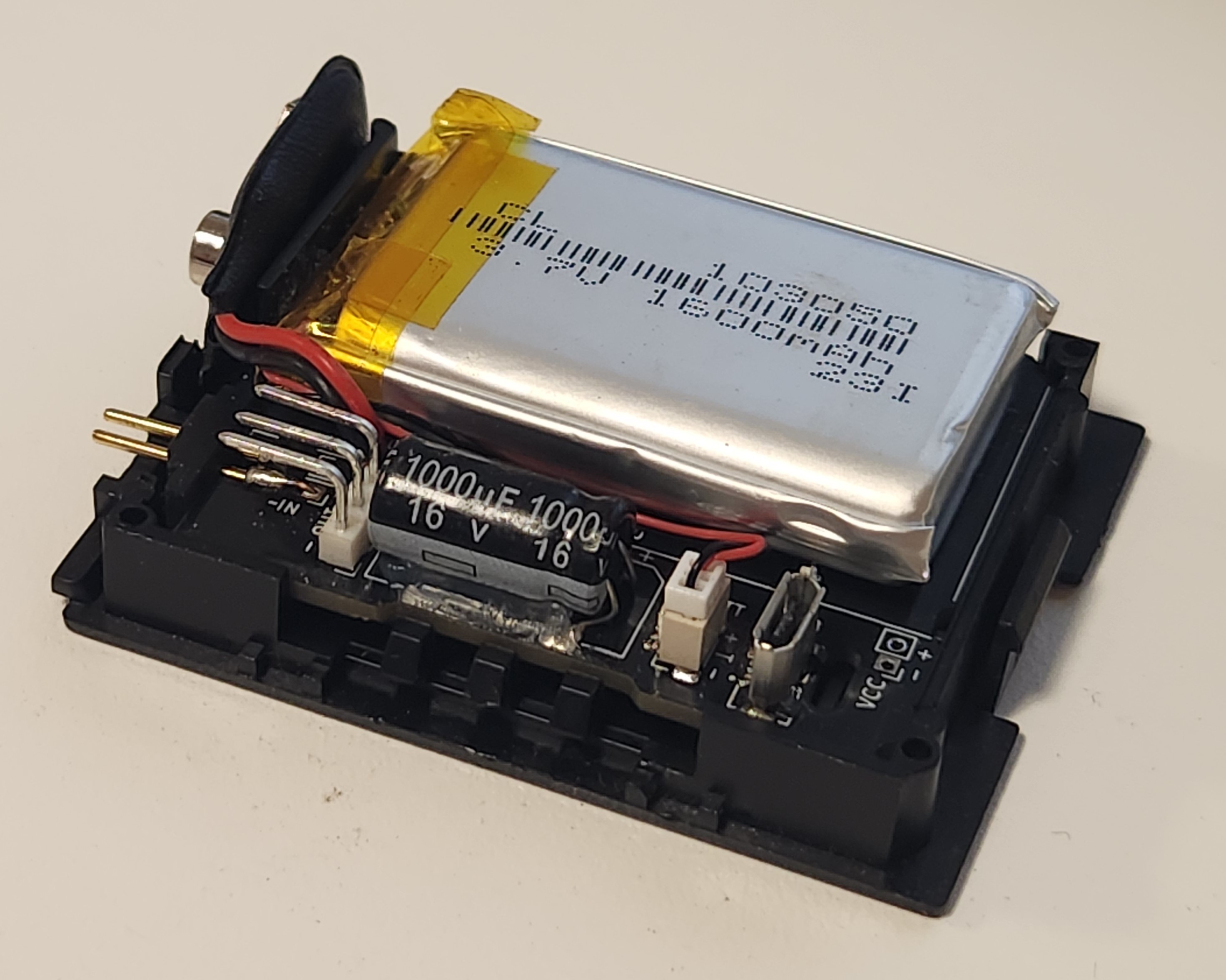
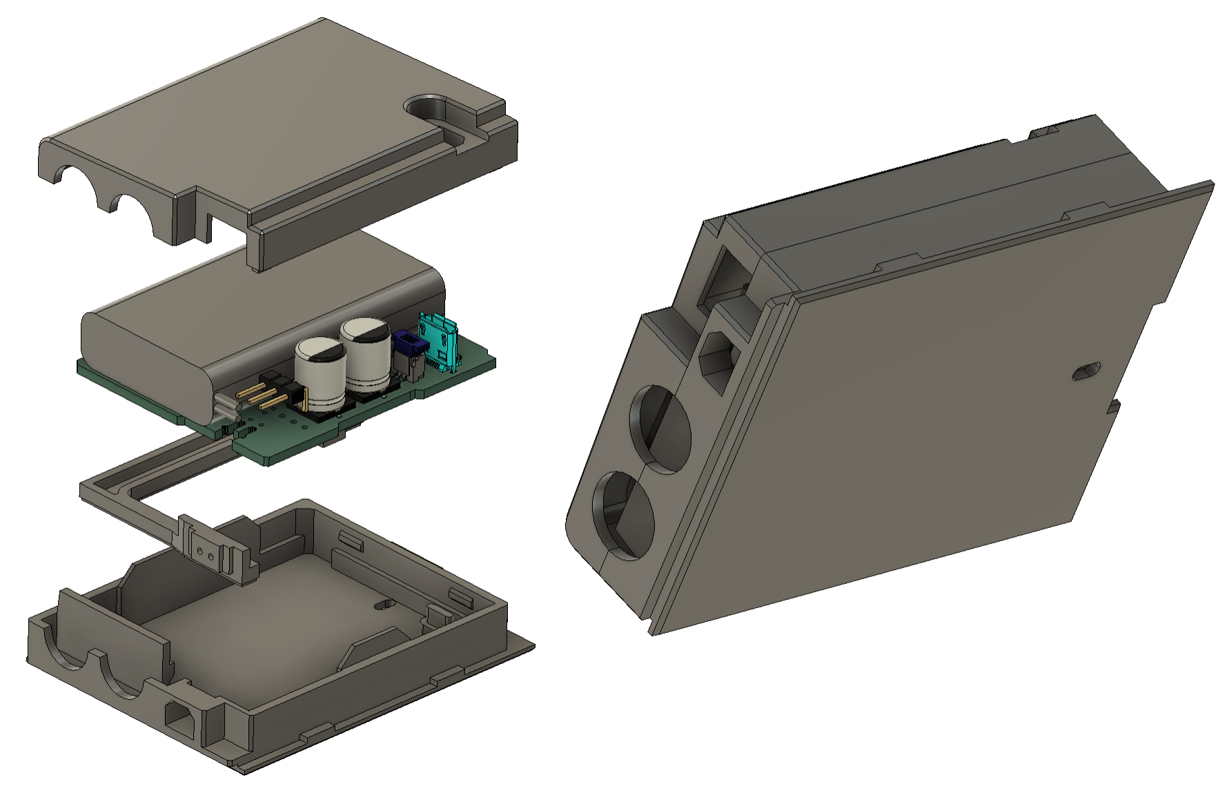
The board is designed to fit into the original TI case bottom part, to preserve an original look!
If you'd like one of these, I may be able to help! Please contact me at info@calcpsu.com.au.
This work is licensed under a Creative Commons Attribution-NonCommercial-ShareAlike 4.0 International License.

| Qty | Value | Footprint | References |
|---|---|---|---|
| 3 | 10k | Resistor_SMD:R_0805_2012Metric | R3, R4, R9 |
| 3 | 1u | Capacitor_SMD:C_0805_2012Metric | C9, C12, C13 |
| 2 | 10uH | george:Inductor_Bourns_SRR4028 | L1, L2 |
| 2 | 3k | Resistor_SMD:R_0805_2012Metric | R8, R11 |
| 2 | 470u/25V | Capacitor_SMD:CP_Elec_8x10.5 | C8, C10 |
| 2 | 4u7 | Capacitor_SMD:C_0805_2012Metric | C6, C7 |
| 2 | PMEG40T10ERX | Diode_SMD:D_SOD-123 | D1, D5 |
| 1 | 1 | Resistor_SMD:R_1210_3225Metric | R7 |
| 1 | 100k | Resistor_SMD:R_0805_2012Metric | R1 |
| 1 | 100p | Capacitor_SMD:C_0805_2012Metric | C1 |
| 1 | 10u | Capacitor_SMD:C_0805_2012Metric | C5 |
| 1 | 16k | Resistor_SMD:R_0805_2012Metric | R2 |
| 1 | 1k8 | Resistor_SMD:R_0805_2012Metric | R5 |
| 1 | 22n | Capacitor_SMD:C_0805_2012Metric | C11 |
| 1 | 22u | Capacitor_SMD:C_1206_3216Metric | C4 |
| 1 | 2N7002 | Package_TO_SOT_SMD:SOT-23 | Q2 |
| 1 | 3k6 | Resistor_SMD:R_0805_2012Metric | R12 |
| 1 | 47k | Resistor_SMD:R_0805_2012Metric | R10 |
| 1 | 49.9k | Resistor_SMD:R_0805_2012Metric | R17 |
| 1 | 9.1k | Resistor_SMD:R_0805_2012Metric | R18 |
| 1 | AO3413 | Package_TO_SOT_SMD:SOT-23 | Q1 |
| 1 | AP63200WU | Package_TO_SOT_SMD:TSOT-23-6 | U5 |
| 1 | APX809S-31SA | Package_TO_SOT_SMD:SOT-23-3 | U2 |
| 1 | B+ | TestPoint:TestPoint_Pad_D1.0mm | TP2 |
| 1 | BLOAD | TestPoint:TestPoint_Pad_D1.0mm | TP3 |
| 1 | BLOADF | TestPoint:TestPoint_Pad_D1.0mm | TP5 |
| 1 | BQ21040 | george:SOT-23-6_TI_DBV6 | U4 |
| 1 | EN | TestPoint:TestPoint_Pad_D1.0mm | TP7 |
| 1 | GND | TestPoint:TestPoint_Pad_D1.0mm | TP6 |
| 1 | GRN | LED_SMD:LED_0805_2012Metric | D4 |
| 1 | LOGO | LOGO | G*** |
| 1 | LiPo | Connector_JST:JST_SH_BM03B-SRSS-TB_1x03-1MP_P1.00mm_Vertical | BT1 |
| 1 | MB14S | Package_TO_SOT_SMD:TO-269AA | D2 |
| 1 | MIC2250-1YD5-TR | george:SOT-23-5_TI_DBV5 | U1 |
| 1 | N/P | Capacitor_SMD:C_0805_2012Metric | C3 |
| 1 | NCP360SNT | george:SOT-23-5_TI_DBV5 | U3 |
| 1 | NCP380 | george:SOT-23-5_TI_DBV5 | U6 |
| 1 | OUT | Connector_PinHeader_2.54mm:PinHeader_1x03_P2.54mm_Vertical | J4 |
| 1 | OUT | Connector_PinHeader_2.00mm:PinHeader_1x02_P2.00mm_Vertical | J2 |
| 1 | PMEG40T10ERX | Diode_SMD:D_SOD-123 | D6 |
| 1 | RED | LED_SMD:LED_0805_2012Metric | D3 |
| 1 | TS | TestPoint:TestPoint_Pad_D1.0mm | TP8 |
| 1 | VAC1 | Connector_PinHeader_2.00mm:PinHeader_1x01_P2.00mm_Vertical | J5 |
| 1 | VAC2 | Connector_PinHeader_2.00mm:PinHeader_1x01_P2.00mm_Vertical | J1 |
| 1 | VCC | TestPoint:TestPoint_Pad_D1.0mm | TP9 |
| 1 | VCC | Connector_PinHeader_2.00mm:PinHeader_1x02_P2.00mm_Vertical | J3 |
| 1 | VINDC | TestPoint:TestPoint_Pad_D1.0mm | TP1 |
| 1 | VOUT | TestPoint:TestPoint_Pad_D1.0mm | TP4 |
| 1 | Z15V | Diode_SMD:D_SMA | D8 |
| 1 | ZX80-B-5P_30_ | mod_local:HRS_ZX80-B-5P_30_ | J7 |
| 1 | \ | LOGO | G*** |
The 60 most common of 62 parts.
It measures 51.4 × 43 mm and has 2 copper layers, 1.6 mm thick.
62 parts, built around the AP63200WU, MIC2250-1YD5-TR, APX809S-31SA and BQ21040DBV. The full list of its parts is on this page, with links to each part's symbol and footprint where PCBKit's library has them.
From the calcpsu/cptibp8 repository on GitHub, at the commit this page was made from: the board is cptibp8-pcb/cptibp8-pcb.kicad_pcb and its schematic cptibp7-original.kicad_sch. PCBKit opens the board in the browser, with nothing to install.
Its repository states no licence, so its author keeps all rights: ask calcpsu before reusing the design.
calcpsu/cphp82001
CalcPack replacement for HP 82001, suits HP35/45/55/65/67 calculators

marchmare/snaphat-pcb
RaspberryPi Zero 2 W addon serving as a handheld photo camera setup

starlightk7/OpenFC
OpenFC Repository for Reproduction PCBs for Early 1980's Famicom Boards. Placeholder: Release Coming Soon!


yvoronkin/FANSTOP
In a small form factor, an extension of the fan control is implemented.

