
2 layers132.3 × 94.9 mm

 yuburoll/KeeNoard5
38-key split keyboard with rotary encoder and single board
KeeNoard SMD is an open-source printed circuit board by yuburoll, from the yuburoll/KeeNoard repository on GitHub, published under the MIT licence. It is a 2-layer board of 131.3 × 99.9 mm with 60 parts on 51 nets, routed with 1,174 tracks and 122 vias.
It is built around the RP2040-ZERO. Its parts include 20 switches, 6 transistors, 1 IC and 1 connector. It belongs with the keyboards and input boards and the RP2040 boards of this library.
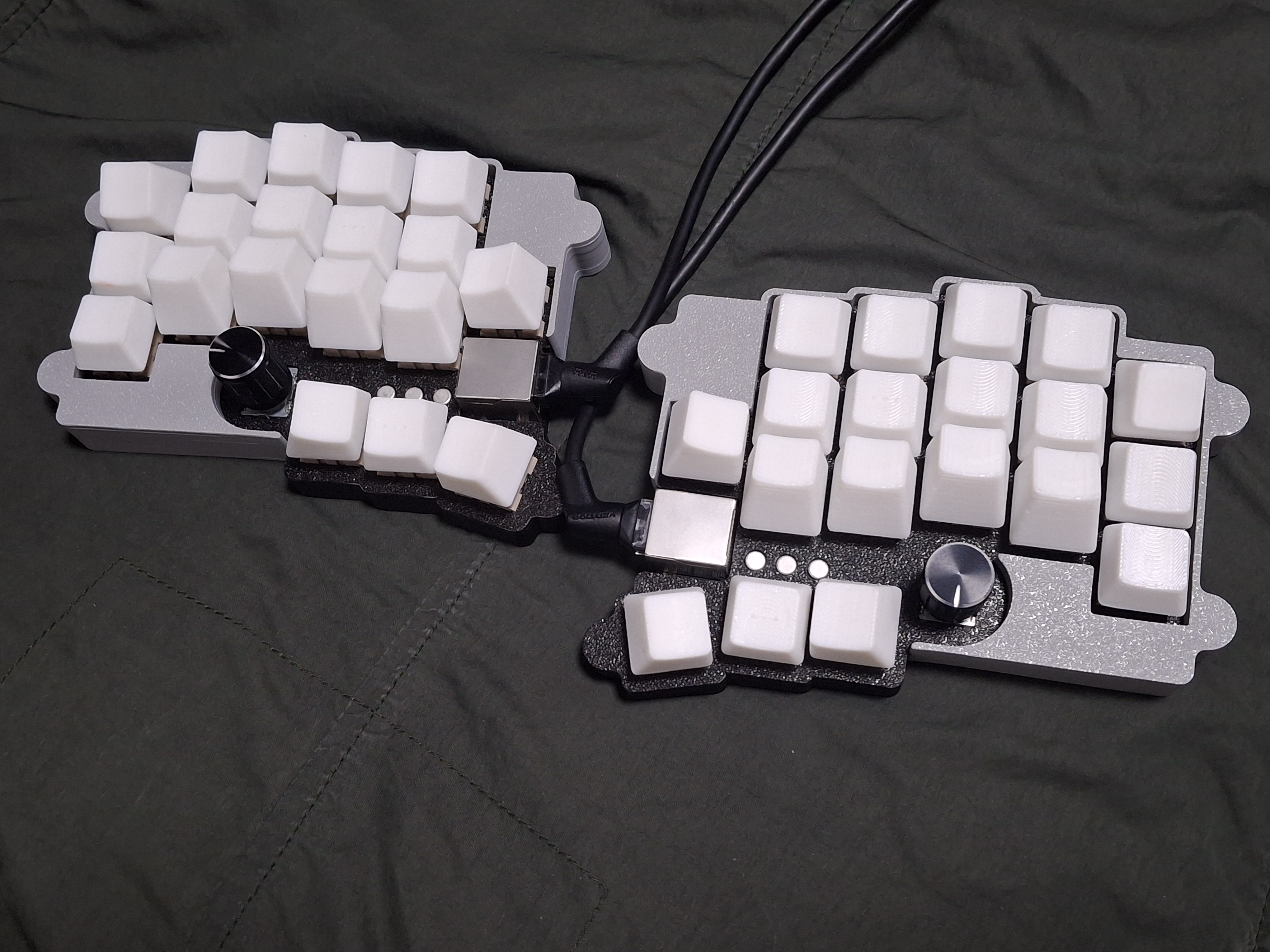
KeeNoard(name intended typo between B and N) is 38-key split keyboard with rotary encoder and multiple center key, with only one rp2040 zero board.
Inspired and learned many thing from the former great Cheapino, KeeNoard uses only one board and Japanese duplex matrix, and controlled ghosting with three PNP transistor and active-high matrix.
Default keymap uses customized Miryoku - with slight different mouse and navigator keys. Two center keys are mapped to left Y and right B, which are originally intended.
1x rp2040 zero (boards formly created by waveshare) (Approx. 2-4$)
2x KeeNoard PCB Boards (5 boards are 9$ on JLC w/o shipping cost)
1x printed case sets, which you want to make it (Approx. 8-12$ if you buy printed one)
6x TO-18 PNP transistors, or 6x SOT-23 PNP transistors. (Approx. 1-2$)
50x diodes (Approx. 1$)
2x EC11 encoders and cap (Approx. 2$)
14x M2x6 screws, flathead (Approx. 1$)
1x RJ45 cable (Approx. 3$)
2x RJ45 connector, in 18mm (Approx. 1$)
38x Keyswitches & Keycaps (Maybe this costs varies too much. 15$ on average)
Approx. 43$-50$(w/o shipping cost) needed to build one
work in progress. sorry!
You can see the images in the folder, which uploaded for build guides. Especially you may see how to solder the controller board, because this uses surface mounting by castelated pins.
Images are captured with prototype version PCB, which is different from the current gerber. current gerber has SMD transistor soldering pads on the protype's label position, and is more easy to solder controller board with larger soldering pads.
This uses qmk to build the firmware. Copy "keenoard" folder which is in "firmware" directory to "qmk_firmware\keyboards" folder, and build it via qmk msys.
Or, simply flash uf2 in "uf2Examples" folder by changing rp2040 zero in dfu mode, which can be executed by holding boot button while plugging in usb c. Vial versions are also prepared - use proper vial firmware, depending on where you placed the controller board.
matrix.c and keymaps follows GNU GPL 2.0 license.
other codes follows MIT license.
all designs and the hardware board follows CC BY-SA 4.0 license.
If you want to make a commercial product, it would be appreciated if you sponsor some bucks for me.
| Qty | Value | Footprint | References |
|---|---|---|---|
| 25 | D | BuckinBCustom:Diode_TH_SMD_REVERSIBLE | D++1, D++2, D++3, D+1, D+2, D+3, D1, D10, D11, D12, D13, D14, D15, D16, D17, D18 +9 |
| 19 | SW_Push | keyswitches:Kailh_socket_MX_optional_reversible | SW1, SW2, SW3, SW4, SW5, SW6, SW10, SW11, SW12, SW13, SW14, SW15, SW16, SW17, SW18, SW19 +3 |
| 7 | SolderJumper | Jumper:SolderJumper-2_P1.3mm_Open_TrianglePad1.0x1.5mm | JP1, JP2, JP3, JP4, JP5, JP6, JP7 |
| 3 | PNP | BuckinBCustom:SOT-23-PNP_REVERSIBLE | Q1, Q2, Q3 |
| 3 | PNP | BuckinBCustom:TO-18-3-PNP_REVERSIBLE | Q1, Q2, Q3 |
| 1 | 8P8C_Shielded | BuckinBCustom:RJ45_Ninigi_GE_REVERSIBLE | J2_RECV1 |
| 1 | RP2040-Zero | BuckinBCustom:RP2040-Zero-OPTIMIZED | U1 |
| 1 | RotaryEncoder_Switch | BuckinBCustom:RotaryEncoder_Alps_EC11E-Switch_Vertical_H20mm_REVERSIBLE | SW20 |


beekeeb/zerosprey42
Zerosprey42 Keyboard is a wired, beginner friendly, choc hotswap, MonoBlockSplit (Unibody), column-staggered, DIY mechanical keyboard.


ravinrabbid/DonCon2040
RP2040 based firmware and hardware for DIY Taiko no Tatsujin Drum Controllers
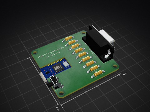
nmur/RP2040-TestPatternGenerator
A simple test pattern generator running on the RP2040 microcontroller

ChrisChrisLoLo/bunchiez40
A pocket keyboard that makes use of mouse switches to achieve a miniscule size

It measures 131.3 × 99.9 mm and has 2 copper layers, 1.6 mm thick.
60 parts, built around the RP2040-ZERO. The full list of its parts is on this page, with links to each part's symbol and footprint where PCBKit's library has them.
From the yuburoll/KeeNoard repository on GitHub, at the commit this page was made from: the board is kicad/KeeNoard-SMD.kicad_pcb and its schematic kicad/KeeNoard-SMD.kicad_sch. PCBKit opens the board in the browser, with nothing to install.
Its repository publishes it under the MIT licence: you may reuse it on that licence's terms (keep the author's notice, and for a copyleft licence share your changes alike).