4 layers68.5 × 89.9 mm

 wvdv2002/SMA-SB2500-Off-Grid11
Try to open source the grid tie solar inverter SMA Sunny Boy SB2500
SB LOGICBOARD V01 is an open-source printed circuit board by wvdv2002, from the wvdv2002/SMA-SB2500-Off-Grid repository on GitHub. It is a 2-layer board of 160 × 84 mm with 119 parts on 137 nets, routed with 1,130 tracks and 236 vias.
It is built around the STM32F405RGT6, LM358D and MCP1826S-3302E/DB, with the 1206DD106KAT2A among its other parts. Its parts include 39 resistors, 34 capacitors, 9 inductors, 5 ICs and 2 crystals. It belongs with the power boards and the STM32 boards of this library.


The grid tie solar inverter SMA Sunny Boy SB2500 is a beautifully designed transformer isolated grid tie inverter. It is probably possible to convert it to an off grid batter inverter by reprogramming or redesigning the logic board
Checkout my hackaday.io page for pictures of the inside of the inverter and a project log.
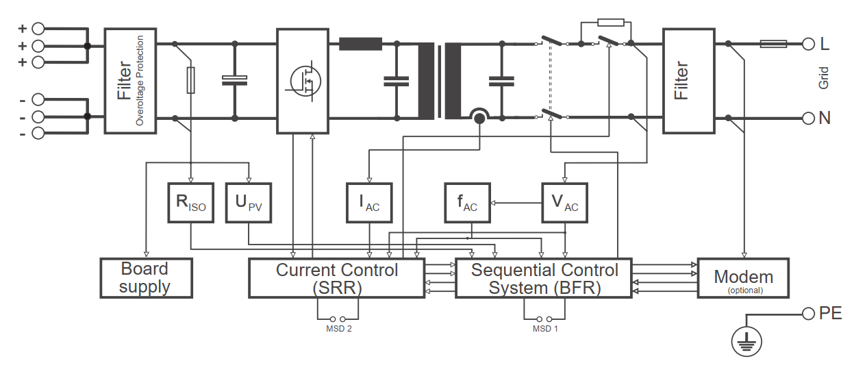 The block diagram from the SB2500 manual.
The inverter has an H-bridge with 4 IGBTs (SKW30NF60) driven by IR2113S mosfet drivers. These drive an 2mH inductor + 4.7uF capacitor step down converter and then a isolation transformer 153V primary/230V secondary 9.6A. On the grid side are three safety relais, EMC filtering and a measurement transformer for the logic board the measure the grid voltages. All the logic is powered from the DC side, several voltages are generated using a switching power converter which generates all the drive voltages for the IGBT drivers and the logi board. The logic board contains an SAFC808 microcontroller, probably with an interchangable AT70C020, 2 MBit memory chip, for grid monitoring and sequencing. A DSP56F803 from Freescale provides the switching waveforms.
The layout is drawn in Kicad.
Exported kicad images (probably not up to date) are in the images folder.
The src folder can contain the Freescale DSP code.
The datasheets folder contains datasheets of most of the electronic parts in the inverter.
| Qty | Value | Footprint | References |
|---|---|---|---|
| 11 | 100n/35v | SB_LOGICBOARD_V01:C0805 | C1, C4, C6, C7, C8, C9, C11, C12, C13, C15, C16 |
| 10 | 100n | SB_LOGICBOARD_V01:C0805 | C2, C3, C10, C14, C17, C20, C25, C31, C61, C74 |
| 9 | 10K | SB_LOGICBOARD_V01:R0805 | R7, R22, R23, R25, R28, R30, R33, R35, R46 |
| 9 | 2.2uf/6.3v/x7r | SB_LOGICBOARD_V01:C0603 | C21, C28, C30, C37, C38, C39, C40, C41, C42 |
| 9 | 22K | SB_LOGICBOARD_V01:R0805 | R8, R24, R26, R27, R29, R32, R34, R36, R47 |
| 9 | LCBB-601 | SB_LOGICBOARD_V01:L0805 | L1, L2, L3, L6, L7, L8, L9, L26, L27 |
| 7 | 10k | SB_LOGICBOARD_V01:R0805 | R3, R12, R14, R17, R20, R39, R41 |
| 6 | JP1E | SB_LOGICBOARD_V01:JP1 | AIN0, JP13, JP15, JP16, JP18, JP19 |
| 4 | 330 | SB_LOGICBOARD_V01:R0805 | R1, R4, R5, R6 |
| 4 | 39k | SB_LOGICBOARD_V01:R0805 | R15, R18, R38, R40 |
| 4 | PINHD-1X7 | SB_LOGICBOARD_V01:1X07 | JP7, JP8, JP11, JP12 |
| 3 | LED5MM | SB_LOGICBOARD_V01:LED5MM | ERR1, OK1, WARN1 |
| 3 | OSR50805C1E | SB_LOGICBOARD_V01:SML0805 | 3V3OK1, 5VOK1, HB1 |
| 3 | PINHD-1X6 | SB_LOGICBOARD_V01:1X06 | JP9, JP10, JP17 |
| 2 | 22k | SB_LOGICBOARD_V01:R0805 | R9, R10 |
| 2 | 22pf | SB_LOGICBOARD_V01:C0805 | C55, C57 |
| 2 | 2k2/1% | SB_LOGICBOARD_V01:R0805 | R108, R109 |
| 2 | 33k | SB_LOGICBOARD_V01:R0805 | R11, R13 |
| 2 | 74HCT244DW OR 74VHCT541A | SB_LOGICBOARD_V01:SO20W | IC2, IC6 |
| 2 | LM358D | SB_LOGICBOARD_V01:SO08 | IC3, IC4 |
| 2 | PINHD-1X20 | SB_LOGICBOARD_V01:1X20 | JP5, JP6 |
| 2 | PINHD-2X7 | SB_LOGICBOARD_V01:2X07 | LCD1, RX485 |
| 1 | 1206DD106KAT2A | SB_LOGICBOARD_V01:C1206 | C26 |
| 1 | 8.00M-CFPX104 | SB_LOGICBOARD_V01:CRYSTAL-SMD-5X3 | Y3 |
| 1 | MA03-1 | SB_LOGICBOARD_V01:MA03-1 | SV1 |
| 1 | MCP1826S-3302ED | SB_LOGICBOARD_V01:SOT223 | IC1 |
| 1 | NC | SB_LOGICBOARD_V01:C0603 | C5 |
| 1 | NC | SB_LOGICBOARD_V01:B2,54 | 3V3 |
| 1 | PINHD-2X20_2MM | SB_LOGICBOARD_V01:2X20_2MM | MAINB1 |
| 1 | PINHD-2X6 | SB_LOGICBOARD_V01:2X06 | ISO1 |
| 1 | SB_LOGIC_PCB | SB_LOGICBOARD_V01:SB-PCB | U$1 |
| 1 | STM32F405RG | SB_LOGICBOARD_V01:TQFP64 | U$5 |
| 1 | W237-4 | SB_LOGICBOARD_V01:W237-4 | X1 |
| 1 | ZL201-06G | SB_LOGICBOARD_V01:1X06_LOCK | J1 |

curiouselectric/Lapse-O-Matic
This is code, PCB and enclosure design for an ESP32_CAM based wildlife camera


svenssonjoel/Mattie
stM32f4 lATTIcE - MATTIE - A PCB with an STM32f4 and a LATTICE FPGA


electgpl/ESP32S3_DEV_Minimal_LowPower
This project implements a minimal low-power development board based on the ESP32-S3. The design focuses on reducing component count, board complexity, and idle power consumption, while still exposing the full…


rheejason/circular-mic-array
UIUC ECE 395: an 8-mic circular beamforming microphone array (steerable conference-table mic and acoustic imager).
It measures 160 × 84 mm and has 2 copper layers, 1.6 mm thick.
119 parts, built around the STM32F405RGT6, LM358D, MCP1826S-3302E/DB and 1206DD106KAT2A. The full list of its parts is on this page, with links to each part's symbol and footprint where PCBKit's library has them.
From the wvdv2002/SMA-SB2500-Off-Grid repository on GitHub, at the commit this page was made from: the board is PCB/kicad/logicBoard/SB_LOGICBOARD_V01.kicad_pcb. PCBKit opens the board in the browser, with nothing to install.
Its repository states no licence, so its author keeps all rights: ask wvdv2002 before reusing the design.