2 layers127 × 57.1 mm

 sphawes/glowtie25
The light-up bowtie you control over Wifi
Glowtie is an open-source printed circuit board by sphawes, from the sphawes/glowtie repository on GitHub. It is a 2-layer board of 127 × 57.1 mm with 56 parts on 43 nets, routed with 487 tracks and 25 vias.
It is built around the ESP-12F, MCP1826S-3302E/DB and MCP73831, with the WS2812B among its other parts. Its parts include 16 diodes, 13 resistors, 10 connectors, 5 ICs and 2 inductors. It belongs with the radio and wireless boards and the ESP8266 boards of this library.


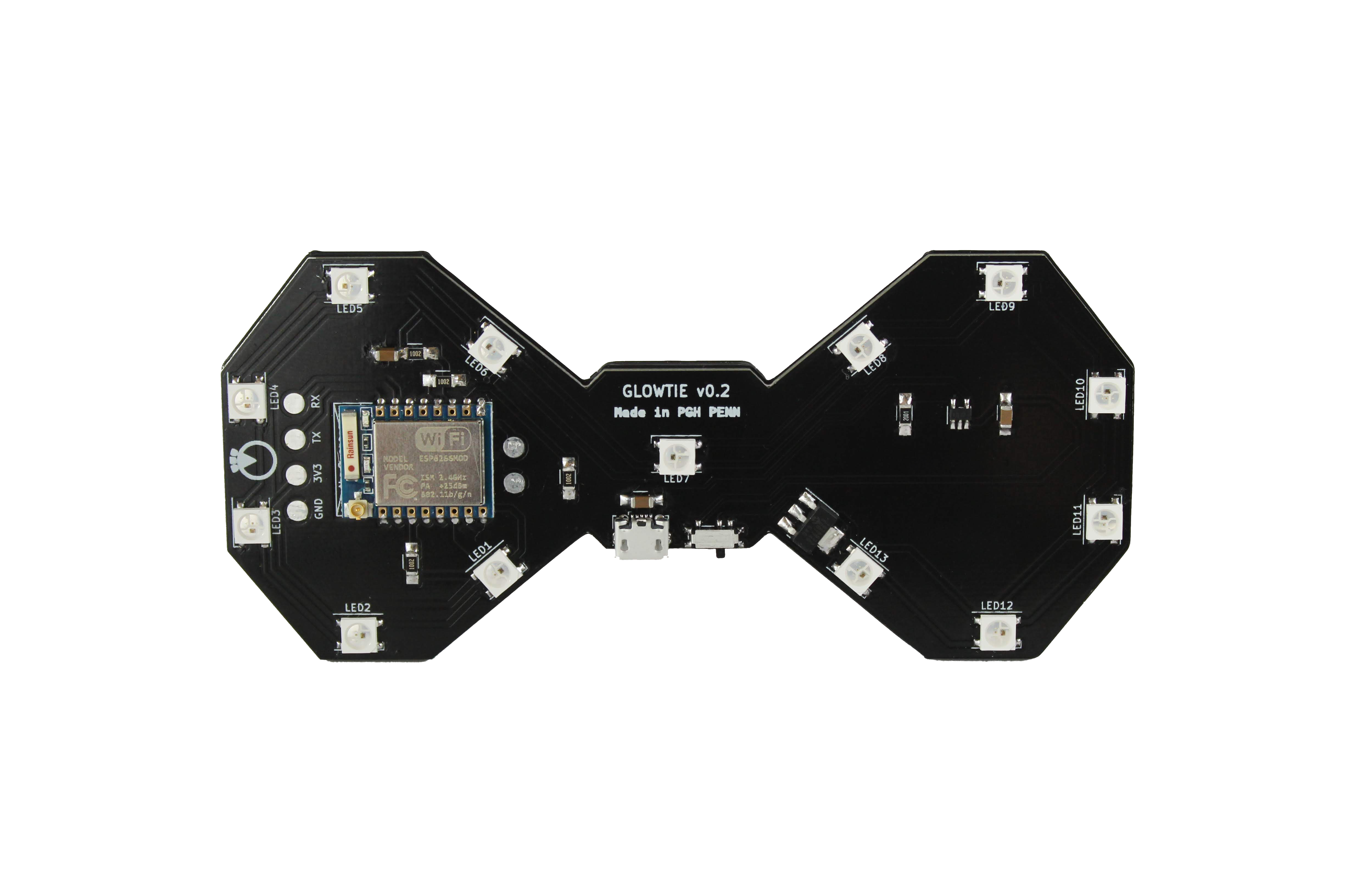
When you load the Glowtie website, you’ll see three sliders. These represent the red, green, and blue values of the lights. When you adjust them, the title background will adjust to show you what color you’re set to.
Once you pick a color, there’s a few options for animations. Tap the button next to the animation you want, then hit the “UPDATE” button. Your Glowtie will change to whatever you selected!

The Glowtie has a built-in memory function, so once you choose a color and animation it’ll remember your choice after you turn it off. This way, you don’t need to connect to it every time you turn it on if you have it set to your favorite pattern.
When the Glowtie has low battery, the center LED will turn red. Use a Micro USB cable to recharge your Glowtie. Make sure your Glowtie is turned off, then plug the Micro USB cable into the port next to the power switch. When you plug the other end into a USB port for power, you should see the top light on your Glowtie illuminate. When it’s done charging, the bottom light will illuminate.
Your Glowtie optionally has a diffusion cover. The cover is held on with a friction fit. Laser cut or print diffusion.dxf in a white or clear material, 1/16" thick. Print bumper.stl in a color of your choice, and super glue the diffusion inside the bumper. The bumper can now be friction fit onto the Glowtie.
The Glowtie is totally open-source. All PCB design files, firmware, and physical parts are hosted on the Github page. There’s a dedicated programming header on the left side so you can add your own animations, or make it do anything you want! Just solder on a few pins and reprogram the ESP8266 over UART.
| Qty | Value | Footprint | References |
|---|---|---|---|
| 13 | WS2812B | LEDs:LED_WS2812B-PLCC4 | LED1, LED2, LED3, LED4, LED5, LED6, LED7, LED8, LED9, LED10, LED11, LED12, LED13 |
| 8 | C | Capacitors_SMD:C_0603 | 1uF1, 1uF3, 10uF1, 10uF2, 10uF3, 10uF4, 10uF5, 10uF6 |
| 6 | 10K | Resistors_SMD:R_0603 | R1, R3, R4, R5, R9, R10 |
| 4 | 2K | Resistors_SMD:R_0603 | R2, R6, R7, R8 |
| 3 | R | Resistors_SMD:R_0603 | R470, R470_1, R470_2 |
| 2 | Ferrite_Bead_Small | Capacitors_SMD:C_0603 | L1, L2 |
| 1 | BOOT2 | Pin_Headers:Pin_Header_Straight_1x01_Pitch2.54mm | J5 |
| 1 | ESP-12F | ESP8266:ESP-12E_SMD | U3 |
| 1 | GND_BATT1 | Measurement_Points:Measurement_Point_Square-SMD-Pad_Big | J6 |
| 1 | GND_BATT2 | Measurement_Points:Measurement_Point_Square-SMD-Pad_Big | J7 |
| 1 | LC709203F | LC709203FQH-01TWG:SON65P400X300X80-9N | U5 |
| 1 | LED(GREEN) | LEDs:LED_0603 | D2 |
| 1 | LED(RED) | LEDs:LED_0603 | D3 |
| 1 | LED(YELLOW) | LEDs:LED_0603 | D1 |
| 1 | MAX9814 | Housings_DFN_QFN:DFN-14-1EP_3x3mm_Pitch0.4mm | U4 |
| 1 | MCP1826S-3302E | TO_SOT_Packages_SMD:SOT-223 | U2 |
| 1 | MCP73831 | TO_SOT_Packages_SMD:SOT-23-5 | U1 |
| 1 | Microphone | stephen:CMC-6013_ELECTRET_MIC | MK1 |
| 1 | POGO_3V3 | Pin_Headers:Pin_Header_Straight_1x01_Pitch2.54mm | J10 |
| 1 | POGO_GND | Pin_Headers:Pin_Header_Straight_1x01_Pitch2.54mm | J11 |
| 1 | POGO_RX | Pin_Headers:Pin_Header_Straight_1x01_Pitch2.54mm | J2 |
| 1 | POGO_TX | Pin_Headers:Pin_Header_Straight_1x01_Pitch2.54mm | J4 |
| 1 | SW_DPST_x2 | Buttons_Switches_SMD:SW_SPDT_PCM12 | SW1 |
| 1 | USB_OTG | Connectors_USB:USB_Micro-B_Molex-105017-0001 | J1 |
| 1 | VBATT1 | Measurement_Points:Measurement_Point_Round-SMD-Pad_Big | J8 |
| 1 | VBATT2 | Measurement_Points:Measurement_Point_Round-SMD-Pad_Big | J9 |


NilsEngelbach/air-quality-pcb
Seventh iteration: ESP8266 → ESP32-C3 (native USB, no UART bridge), fixes from the v6 design review, right-angle switches with longer actuators, a STEMMA QT port for optional sensors, and charge-status sensing.


curiouselectric/Lapse-O-Matic
This is code, PCB and enclosure design for an ESP32_CAM based wildlife camera

wvdv2002/SMA-SB2500-Off-Grid
Try to open source the grid tie solar inverter SMA Sunny Boy SB2500

svenssonjoel/Mattie
stM32f4 lATTIcE - MATTIE - A PCB with an STM32f4 and a LATTICE FPGA


electgpl/ESP32S3_DEV_Minimal_LowPower
This project implements a minimal low-power development board based on the ESP32-S3. The design focuses on reducing component count, board complexity, and idle power consumption, while still exposing the full…

It measures 127 × 57.1 mm and has 2 copper layers, 1.6 mm thick.
56 parts, built around the ESP-12F, MCP1826S-3302E/DB, MCP73831 and WS2812B. The full list of its parts is on this page, with links to each part's symbol and footprint where PCBKit's library has them.
From the sphawes/glowtie repository on GitHub, at the commit this page was made from: the board is pcb/V0.3/glowtie.kicad_pcb and its schematic pcb/V1.0/glowtie.kicad_sch. PCBKit opens the board in the browser, with nothing to install.
Its repository states no licence, so its author keeps all rights: ask sphawes before reusing the design.