
2 layers36.1 × 21 mm

CMSIS-DAP compatible wireless debugger for ESP8266/ESP32/ESP32C3/ESP32S3. Optional 40MHz SPI acceleration, etc. 适配多种ESP芯片的无线调试器
ESP8266 is an open-source printed circuit board by windowsair, from the windowsair/wireless-esp8266-dap repository on GitHub, published under the MIT licence. It is a 2-layer board of 40 × 20 mm with 39 parts on 42 nets, routed with 268 tracks and 75 vias.
It is built around the CH330N and ESP8266EX. Its parts include 17 capacitors, 10 resistors, 4 ICs, 2 connectors and 2 switches. It belongs with the radio and wireless boards and the ESP32, ESP8266 and RISC-V boards of this library.


 master
 develop


Wireless debugging with only one ESP Chip !
Realized by USBIP and CMSIS-DAP protocol stack.
👉 5m range, 100kb size firmware(Hex) earse and download test:

For Keil users, we now also support elaphureLink. No need for usbip to start your wireless debugging!
SoC Compatibility
Debug Communication Mode
USB Communication Mode
Debug Trace (Uart)
More..
The default connected WIFI SSID is DAP or OTA , password 12345678
Support for specifying multiple possible WAP. It can be added here: wifi_configuration.h
You can also specify your IP in the above file (We recommend using the static address binding feature of the router).

There is built-in ipv4 only mDNS server. You can access the device using dap.local.
The mDNS in ESP8266 only supports ipv4.

| SWD | |
|---|---|
| SWCLK | GPIO14 |
| SWDIO | GPIO13 |
| TVCC | 3V3 |
| GND | GND |
| JTAG | |
|---|---|
| TCK | GPIO14 |
| TMS | GPIO13 |
| TDI | GPIO4 |
| TDO | GPIO16 |
| nTRST (optional) | GPIO0* |
| nRESET | GPIO5 |
| TVCC | 3V3 |
| GND | GND |
| Other | |
|---|---|
| LED_WIFI_STATUS | GPIO15 |
| Tx | GPIO2 |
| Rx | GPIO3 (U0RXD) |
Rx and Tx is used for uart bridge, not enabled by default.
| SWD | |
|---|---|
| SWCLK | GPIO14 |
| SWDIO | GPIO13 |
| TVCC | 3V3 |
| GND | GND |
| JTAG | |
|---|---|
| TCK | GPIO14 |
| TMS | GPIO13 |
| TDI | GPIO18 |
| TDO | GPIO19 |
| nTRST (optional) | GPIO25 |
| nRESET | GPIO26 |
| TVCC | 3V3 |
| GND | GND |
| Other | |
|---|---|
| LED_WIFI_STATUS | GPIO27 |
| Tx | GPIO23 |
| Rx | GPIO22 |
Rx and Tx is used for uart bridge, not enabled by default.
| SWD | |
|---|---|
| SWCLK | GPIO6 |
| SWDIO | GPIO7 |
| TVCC | 3V3 |
| GND | GND |
| JTAG | |
|---|---|
| TCK | GPIO6 |
| TMS | GPIO7 |
| TDI | GPIO9 |
| TDO | GPIO8 |
| nTRST (optional) | GPIO4 |
| nRESET | GPIO5 |
| TVCC | 3V3 |
| GND | GND |
| Other | |
|---|---|
| LED_WIFI_STATUS | GPIO10 |
| Tx | GPIO19 |
| Rx | GPIO18 |
Rx and Tx is used for uart bridge, not enabled by default.
| SWD | |
|---|---|
| SWCLK | GPIO12 |
| SWDIO | GPIO11 |
| TVCC | 3V3 |
| GND | GND |
| JTAG | |
|---|---|
| TCK | GPIO12 |
| TMS | GPIO11 |
| TDI | GPIO10 |
| TDO | GPIO9 |
| nTRST (optional) | GPIO14 |
| nRESET | GPIO13 |
| TVCC | 3V3 |
| GND | GND |
Only a hardware reference for the ESP8266 is currently available.
Here we provide a simple example for reference:

Alternatively, you can connect directly with wires as we gave at the beginning, without additional circuits.
In addition, a complete hardware reference design is available from contributors, see circuit
You can build locally or use Github Action to build online and then download firmware to flash.
Get ESP8266 RTOS Software Development Kit
The SDK is already included in the project. Please don't use other versions of the SDK.
Build & Flash
Build with ESP-IDF build system. More information can be found at the following link: Build System
The following example shows a possible way to build on Windows:
# Build
python ./idf.py build
# Flash
python ./idf.py -p /dev/ttyS5 flashGet esp-idf
For now, please use esp-idf v6.1 : https://github.com/espressif/esp-idf/releases/tag/v6.1
Build & Flash
Build with ESP-IDF build system. More information can be found at the following link: Build System
The following example shows a possible way to build:
# Set build target
idf.py set-target esp32
# Build
idf.py build
# Flash
idf.py -p /dev/ttyS5 flash
The
idf.pyin the project root directory is only applicable to the old ESP8266 target. Don't use it in ESP32.
We also provided sample firmware for quick evaluation. See Releases
Start ESP chip and connect it to the device to be debugged
Connect it with usbip:
# HID Mode only
# for pre-compiled version on SourceForge
# or usbip old version
.\usbip.exe -D -a <your-esp-device-ip-address>  1-1

# 👉 Recommend
# HID Mode Or WinUSB Mode
# for usbip-win 0.3.0 kmdf ude
.\usbip.exe attach_ude -r <your-esp-device-ip-address> -b 1-1
If all goes well, you should see your device connected.

Here, we use MDK for testing:

Note that this project is sensitive to the network environment. If you are using a hotspot on your computer, you can try using network analyzer such as wireshark to observe the status of your AP network. During the idle time, the network should stay silent, while in the working state, there should be no too much packet loss.
Some LAN broadcast packets can cause serious impact, including:
For ESP8266, this is not far from UDP FLOOD...😰
It is also affected by the surrounding radio environment, your AP situation (some NICs have terrible AP performance), distance, etc.
The maximum rate of esp8266 pure IO is about 2MHz. When you select max clock, we will take the following actions:
clock < 2Mhz : Similar to the clock speed you choose.2MHz <= clock < 10MHz : Use the fastest pure IO speed.clock >= 10MHz : SPI acceleration using 40MHz clock.Note that the most significant speed constraint of this project is still the TCP connection speed.
This project was originally designed to run on Keil, but now you can also perform firmware flash on OpenOCD.
> halt
> flash write_image [erase] [unlock] filename [offset] [type]
pyOCD is now supported.
When this project is updated, you can update the firmware over the air.
Visit the following website for OTA operations: online OTA
For most devices, you don't need to care about flash size. However, improper setting of the flash size may cause the OTA to fail. In this case, please change the flash size with idf.py menuconfig, or modify sdkconfig:
# Choose a flash size.
CONFIG_ESPTOOLPY_FLASHSIZE_1MB=y
CONFIG_ESPTOOLPY_FLASHSIZE_2MB=y
CONFIG_ESPTOOLPY_FLASHSIZE_4MB=y
CONFIG_ESPTOOLPY_FLASHSIZE_8MB=y
CONFIG_ESPTOOLPY_FLASHSIZE_16MB=y

# Then set a flash size
CONFIG_ESPTOOLPY_FLASHSIZE="2MB"
If flash size is 2MB, the sdkconfig file might look like this:
CONFIG_ESPTOOLPY_FLASHSIZE_2MB=y
CONFIG_ESPTOOLPY_FLASHSIZE="2MB"
For devices with 1MB flash size such as ESP8285, the following changes must be made:
CONFIG_PARTITION_TABLE_FILENAME="partitions_two_ota.1MB.csv"
CONFIG_ESPTOOLPY_FLASHSIZE_1MB=y
CONFIG_ESPTOOLPY_FLASHSIZE="1MB"
CONFIG_ESP8266_BOOT_COPY_APP=y
The flash size of the board can be checked with the esptool.py tool:
esptool.py -p (PORT) flash_idThis feature provides a bridge between TCP and Uart:
Send data   ->  TCP  ->  Uart TX -> external devices

Recv data   <-  TCP  <-  Uart Rx <- external devices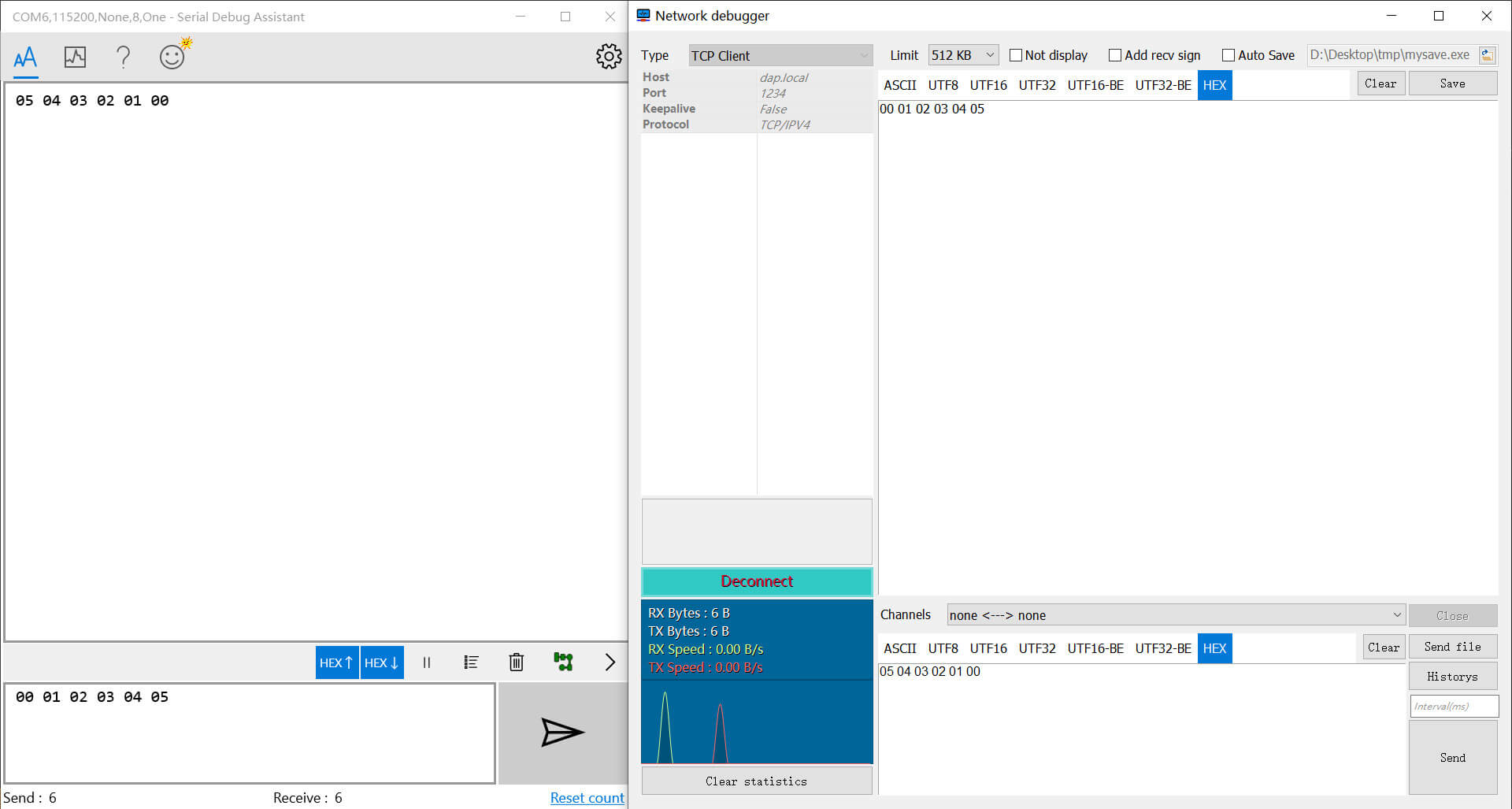
When the TCP connection is established, bridge will try to resolve the text sent for the first packet. When the text is a valid baud rate, bridge will switch to it.
For example, sending the ASCII text 115200 will switch the baud rate to 115200.
For performance reasons, this feature is not enabled by default. You can modify wifi_configuration.h to turn it on.
For the ESP8266, this feature is turned off by default. You can turn it on in menuconfig:
CONFIG_USE_WEBSOCKET_DAP=yCheck other branches to know the latest development progress.
Any kind of contribute is welcome, including but not limited to new features, ideas about circuits, documentation.
You can also ask questions to make this project better.
2020.12.1
TCP transmission speed needs to be further improved.
2020.11.11
Winusb is now available, but it is very slow.
2020.2.4
Due to the limitation of USB-HID (I'm not sure if this is a problem with USBIP or Windows), now each URB packet can only reach 255 bytes (About 1MBps bandwidth), which has not reached the upper limit of ESP8266 transmission bandwidth.
I now have an idea to construct a Man-in-the-middle between the two to forward traffic, thereby increasing the bandwidth of each transmission.
2020.1.31
At present, the adaptation to WCID, WinUSB, etc. has all been completed. However, when transmitting data on the endpoint, we received an error message from USBIP. This is most likely a problem with the USBIP project itself.
Due to the completeness of the USBIP protocol document, we have not yet understood its role in the Bulk transmission process, which may also lead to errors in subsequent processes.
We will continue to try to make it work on USB HID. Once the USBIP problem is solved, we will immediately transfer it to work on WinUSB
Credits to the following project, people and organizations:
- https://github.com/thevoidnn/esp8266-wifi-cmsis-dap for adapter firmware based on CMSIS-DAP v1.0
- https://github.com/ARM-software/CMSIS_5 for CMSIS
- https://github.com/cezanne/usbip-win for usbip windows
| Qty | Value | Footprint | References |
|---|---|---|---|
| 11 | 100nF | Capacitor_SMD:C_0603_1608Metric | C3, C5, C6, C8, C9, C12, C13, C14, C15, C16, C17 |
| 6 | 10kR | Resistor_SMD:R_0603_1608Metric | R2, R4, R5, R6, R9, R10 |
| 2 | 18pF | Capacitor_SMD:C_0603_1608Metric | C10, C11 |
| 2 | SW_DIP_x01 | Button_Switch_SMD:SW_Push_SPST_NO_Alps_SKRK | K1, K2 |
| 1 | 10uF | Capacitor_SMD:C_0603_1608Metric | C1 |
| 1 | 12kR | Resistor_SMD:R_0603_1608Metric | R3 |
| 1 | 1kR | Resistor_SMD:R_0603_1608Metric | R1 |
| 1 | 1uF | Capacitor_SMD:C_0603_1608Metric | C4 |
| 1 | 2.2nH | Inductor_SMD:L_0603_1608Metric | L1 |
| 1 | 2.4pF | Capacitor_SMD:C_0603_1608Metric | C2 |
| 1 | 200R | Resistor_SMD:R_0603_1608Metric | R7 |
| 1 | 26MHz | Crystal:Crystal_SMD_3225-4Pin_3.2x2.5mm | Y1 |
| 1 | 3.0pF | Capacitor_SMD:C_0603_1608Metric | C7 |
| 1 | 499R | Resistor_SMD:R_0603_1608Metric | R8 |
| 1 | CH330N | Package_SO:SOIC-8_3.9x4.9mm_P1.27mm | U4 |
| 1 | Conn_01x02 | RF_Antenna:Johanson_2450AT18x100 | ANT1 |
| 1 | Conn_02x04_Odd_Even | Connector_PinHeader_1.27mm:PinHeader_2x04_P1.27mm_Vertical_SMD | J1 |
| 1 | ESP8266EX | ESP8266:ESP8266 | U2 |
| 1 | HX9193 | Package_TO_SOT_SMD:SOT-23-5 | U3 |
| 1 | LED | LED_SMD:LED_0603_1608Metric | D1 |
| 1 | USB_C_Plug_USB2.0 | Connector_USB:USB_C_Receptacle_HRO_TYPE-C-31-M-12 | P1 |
| 1 | W25Q64 | Package_SO:SOIC-8_5.23x5.23mm_P1.27mm | U1 |


szbeni/forcegauge
Traning for climbing. Load cell with HX711 and real time plotting,

Icey7122/AM32_AI8051U
Using PWMA to output 3 sets of complementary PWM for driving MOSFEET, Using PWMB for capturing external throttle signals, Using ADC to sample voltage and current, for low voltage protection and over current…


TG9541/stm8s001ch330
USB Dongle STM8S001J3M3 with CH330N, e.g. for STM8 eForth
It measures 40 × 20 mm and has 2 copper layers, 1.6 mm thick.
39 parts, built around the CH330N and ESP8266EX. The full list of its parts is on this page, with links to each part's symbol and footprint where PCBKit's library has them.
From the windowsair/wireless-esp8266-dap repository on GitHub, at the commit this page was made from: the board is circuit/ESP8266.kicad_pcb and its schematic circuit/ESP8266.kicad_sch. PCBKit opens the board in the browser, with nothing to install.
Its repository publishes it under the MIT licence: you may reuse it on that licence's terms (keep the author's notice, and for a copyleft licence share your changes alike).