2 layers56 × 110 mm
Trs pcb
Windfisch/midikraken
A open source, open hardware up-to-16x USB-MIDI-interface for around 15 bucks in its smallest configuration.
125 parts28

 Windfisch/midikraken28
A open source, open hardware up-to-16x USB-MIDI-interface for around 15 bucks in its smallest configuration.
Din5 pcb is an open-source printed circuit board by Windfisch, from the Windfisch/midikraken repository on GitHub. It is a 2-layer board of 56 × 110 mm with 82 parts on 72 nets, routed with 1,020 tracks and 17 vias.
It is built around the 74HCT245, HCPL2630M and 74HC165D, with the 74HC595 among its other parts. Its parts include 25 resistors, 24 connectors, 8 diodes, 5 ICs and 2 capacitors. It belongs with the audio and music and interfaces and adapters boards of this library.


An open-source, open-hardware MIDI-USB-interface supporting up to 16 (and maybe beyond?) MIDI ports. The hardware is based on a STM32F103 "blue pill" board which can be cheaply sourced from your favourite chinese seller (note about quality differences), plus other garden variety components such as HC2630 opto couplers (that's just two 6N137 in one package), shift registers, some LEDs and resistors.
Apart from being a MIDI-USB-interface, Midikraken is a feature-packed MIDI router supporting separate clock and note event routing, clock division. Future features may include split-keyboard routing, clock generation or even a hardware arpeggiator.
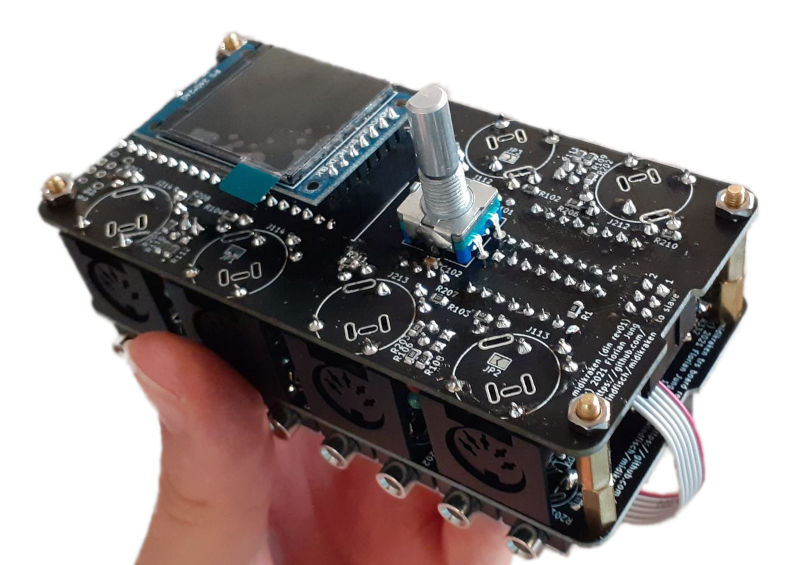
Below you will find a technical overview. A user manual is available here.
Find the latest firmware upgrade packages on the releases page. You only need an USB cable, instructions for Linux and Windows are included.
The schematics and board layout files are on a separate page. Hardware and firmware are versioned separately, their numbers do not match.
Midikraken consists of two different PCBs that can be stacked (almost) arbitrarily: The DIN board has four traditional MIDI in/out port pairs, and can house the master microcontroller.
The TRS board gives you eight TRS MIDI pairs that support both TRS-A and TRS-B. (Inputs are automatic, outputs need to be configured in software). It can not house the microcontroller and thus cannot be used without a DIN board.
The boards can be chained using their master/slave connectors and are stackable using M3 screws / spacers. Currently, the firmware must be adapted and recompiled according to the stack configuration. Currently, a maximum of 16 port pairs is supported.
For information on the hardware, the revision history and errata, see the hardware documentation. A build guide for rev01 and rev02 is available.
The firmware is written in Rust and is released under the GPLv3 license.
Since the STM32F103 only offers 3 hardware UARTs, we need to emulate the UART protocol in software. For this, a timer interrupt oversamples the UART input pins with thrice the baudrate in order to always read a stable bit at a non-edge. (Guaranteed 1/3 * bit time distance from any edge, so the signal should be quite stable until then.)
Benchmarks show that this can be done fast enough for up to 16 software UARTs (and likely even more), while leaving plenty of cpu cycles (25% for 16 UARTs) free for other work.
Further information about the firmware itself can be found in the firmware documentation.
The software in the firmware directory can be redistributed and/or modified under the terms of the GNU General Public License Version 3. Note this does not apply to the bootloader which is under its own license.
The hardware designs in the hardware directory, excluding hardware/lib/3d to which own conditions apply, can be licensed under the terms of the CERN OHL Version 2 license. This specifically includes (but is not limited to) schematics, PCB designs and gerber files.
I am happy about contributions, just open a pull request!
Note: Even though Midikraken is licensed under GPLv3 and OHL-S-v2 (the exact versions), any contributions / pull requests must be licensed under the "GPLv3 or any later version" or "OHL-S-v2 or any later version", respectively. This is because on the one hand, I want to be able to update the project to new versions of these licenses, but on the other hand, I don't like licensing my work under a license (e.g. the hypothetical GPLv4) that I haven't even read yet. If such a license is released, I will likely adopt it after revising it.
| Qty | Value | Footprint | References |
|---|---|---|---|
| 16 | 220 | Resistor_SMD:R_0805_2012Metric | R101, R102, R103, R104, R107, R108, R111, R112, R205, R206, R207, R208, R209, R210, R211, R212 |
| 8 | 1k | Resistor_SMD:R_0805_2012Metric | R105, R106, R109, R110, R201, R202, R203, R204 |
| 8 | DIN-5_180degree | footprints:DIN5 | J101, J102, J103, J104, J201, J202, J203, J204 |
| 8 | do not equip | footprints:din5-frickel | J111, J112, J113, J114, J211, J212, J213, J214 |
| 4 | LED | LED_THT:LED_D3.0mm_Horizontal_O1.27mm_Z2.0mm | D101, D102, D103, D104 |
| 4 | MountingHole_3.2mm_M3_DIN965 | MountingHole:MountingHole_3.2mm_M3_DIN965 | hole1, hole2, hole3, hole4 |
| 4 | SolderJumper_2_Open | Jumper:SolderJumper-2_P1.3mm_Open_TrianglePad1.0x1.5mm | JP1, JP2, JP3, JP4 |
| 4 | SolderJumper_3_Open | Jumper:SolderJumper-3_P1.3mm_Open_RoundedPad1.0x1.5mm | JP5, JP6, JP7, JP8 |
| 4 | yellow | LED_THT:LED_D3.0mm_Horizontal_O3.81mm_Z6.0mm | D201, D202, D203, D204 |
| 2 | 100n | Capacitor_SMD:C_0805_2012Metric | C101, C102 |
| 2 | Conn_02x02_Odd_Even | Connector_PinHeader_2.54mm:PinHeader_2x02_P2.54mm_Vertical | J6, J7 |
| 2 | Conn_02x03_Odd_Even | Connector_IDC:IDC-Header_2x03_P2.54mm_Vertical | J2, J3 |
| 2 | HCPL-2630 | Package_DIP:DIP-8_W7.62mm | U101, U102 |
| 2 | SolderJumper_3_Bridged12 | Jumper:SolderJumper-3_P1.3mm_Open_RoundedPad1.0x1.5mm | JP9, JP14 |
| 2 | USB_B_Micro | Connector_USB:USB_Micro-B_Wuerth_629105150521 | J4, J5 |
| 1 | 74HC165 | Package_DIP:DIP-16_W7.62mm | U3 |
| 1 | 74HC595 | Package_DIP:DIP-16_W7.62mm | U2 |
| 1 | 74HCT245 | Package_DIP:DIP-20_W7.62mm | U1 |
| 1 | BluePill | footprints:BLUEPILL-blackpill | A1 |
| 1 | Conn_01x03_Male | Connector_PinHeader_2.54mm:PinHeader_1x03_P2.54mm_Horizontal | J1 |
| 1 | Conn_01x07 | Connector_PinHeader_2.54mm:PinHeader_1x07_P2.54mm_Vertical | J8 |
| 1 | LOGO | windfisch:windfisch_smaller | wf |
| 1 | OSHW-Logo2_9.8x8mm_SilkScreen | Symbol:OSHW-Logo2_9.8x8mm_SilkScreen | oh |
| 1 | R | Resistor_SMD:R_0805_2012Metric | R1 |
| 1 | Rotary_Encoder_Switch | Rotary_Encoder:RotaryEncoder_Alps_EC11E-Switch_Vertical_H20mm | SW1 |
Windfisch/midikraken
A open source, open hardware up-to-16x USB-MIDI-interface for around 15 bucks in its smallest configuration.

Windfisch/midikraken
A open source, open hardware up-to-16x USB-MIDI-interface for around 15 bucks in its smallest configuration.

JhonVelasquez/Embedded_system_Synchronize_Plant
Project of a embedded system that synchronizes signals in a plant. There is electronic (PCB) and software design (FreeRTOS for STM32F7).


tioluwanimofe/neocera-test-junior-project-2024_2025
report for junior design project class


dwmorrin/teensy-step-sequencer
hardware-based step sequencer using the Teensy 4.1 microcontroller

Sutthiphong-H/project-flip-disc
FlipDisc Project was made for education of Project. Chadsadakorn Piriyasiriphan Jadesalit Suriyanimitsuk Sutthiphong Hongkham

slu4coder/Minimal-64x4-Home-Computer
My DIY TTL home computer with VGA and PS/2 and 4x the processing power of a Commodore C64 or Apple II.

westlicht/performer-hardware
PER|FORMER Eurorack Sequencer - Hardware Design Files
It measures 56 × 110 mm and has 2 copper layers, 1.6 mm thick.
82 parts, built around the 74HCT245, HCPL2630M, 74HC165D and 74HC595. The full list of its parts is on this page, with links to each part's symbol and footprint where PCBKit's library has them.
From the Windfisch/midikraken repository on GitHub, at the commit this page was made from: the board is hardware/din5_pcb/din5_pcb.kicad_pcb. PCBKit opens the board in the browser, with nothing to install.
Its repository states no licence, so its author keeps all rights: ask Windfisch before reusing the design.