2 layers340 × 100 mm
Switchplate
dwmorrin/teensy-step-sequencer
hardware-based step sequencer using the Teensy 4.1 microcontroller
9 parts

 dwmorrin/teensy-step-sequencer
hardware-based step sequencer using the Teensy 4.1 microcontroller
Teensy step sequencer is an open-source printed circuit board by dwmorrin, from the dwmorrin/teensy-step-sequencer repository on GitHub. It is a 2-layer board of 340 × 100 mm with 151 parts on 153 nets, routed with 803 tracks and 84 vias.
It is built around the 74HCT245, TEENSY 4.1 and 74HC595. Its parts include 66 diodes, 36 resistors, 32 switches, 4 capacitors and 4 ICs. It belongs with the NXP (LPC, Kinetis, i.MX RT) boards of this library.


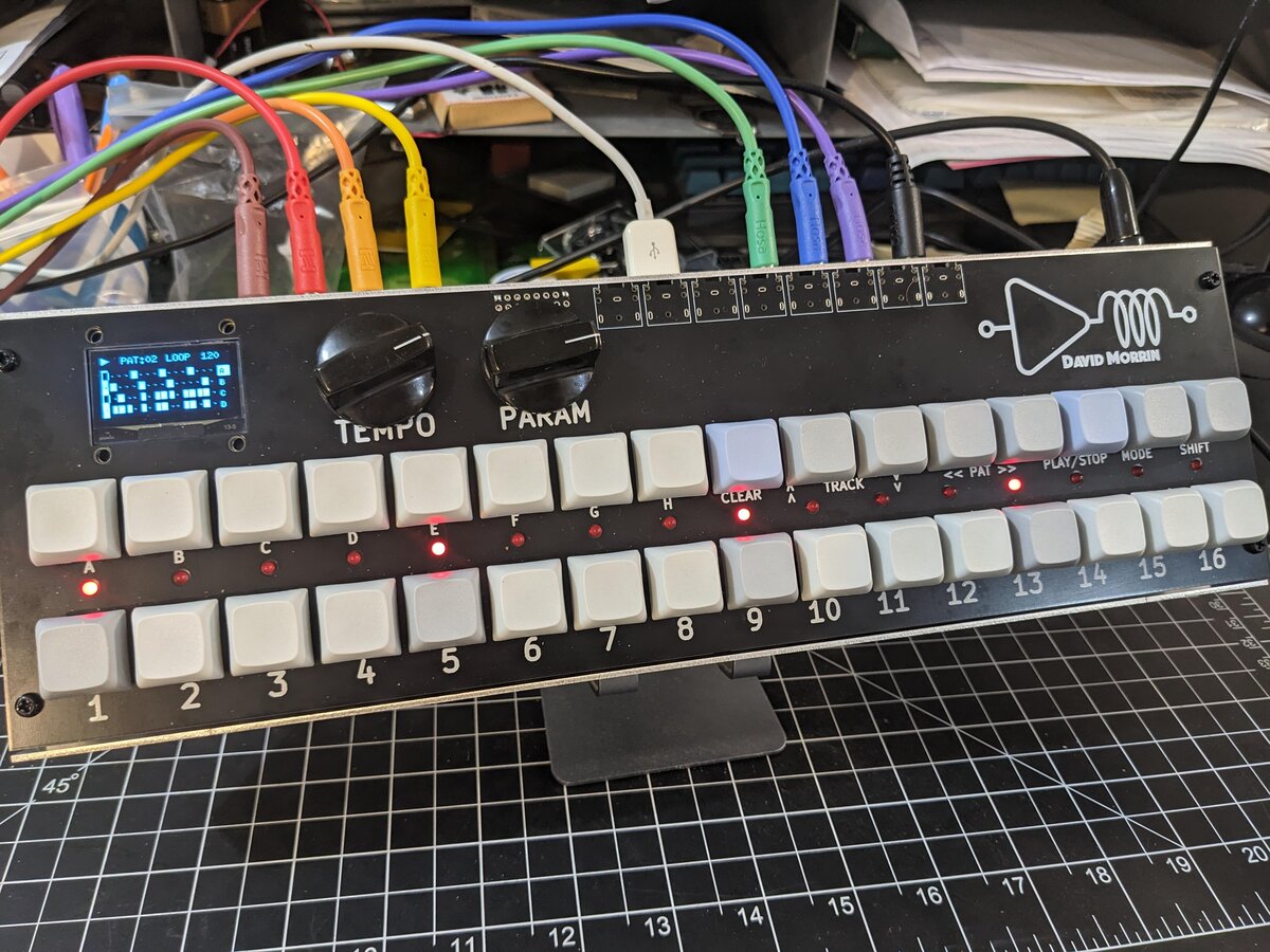
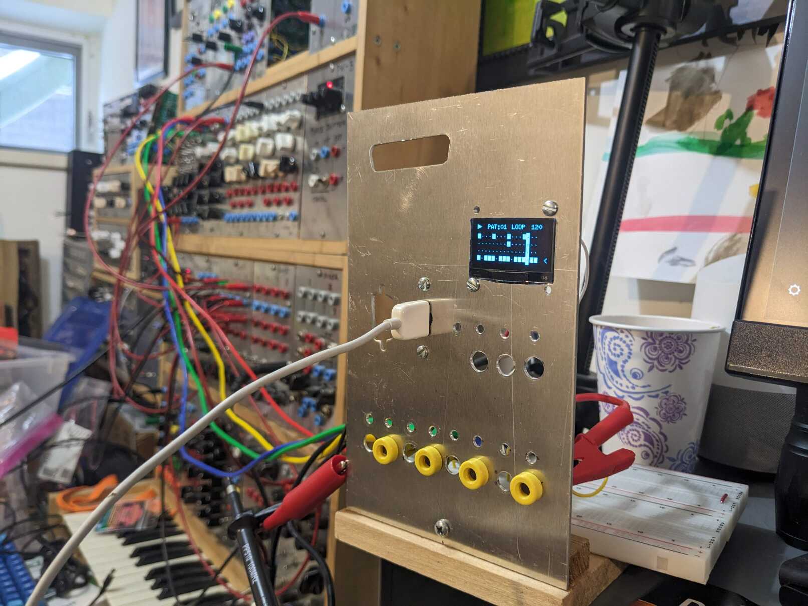
This project implements a hardware-based step sequencer using the Teensy 4.1 microcontroller. It utilizes the Teensy's onboard USB Host capabilities to accept input from standard USB keyboards, alongside a custom 32-switch diode matrix for tactile control.
| Main Board | Switchplate |
|---|---|
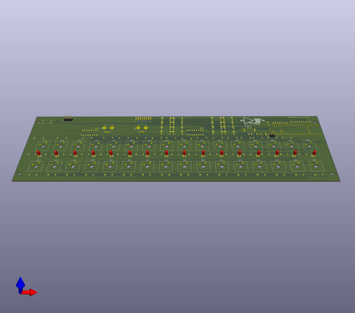 | 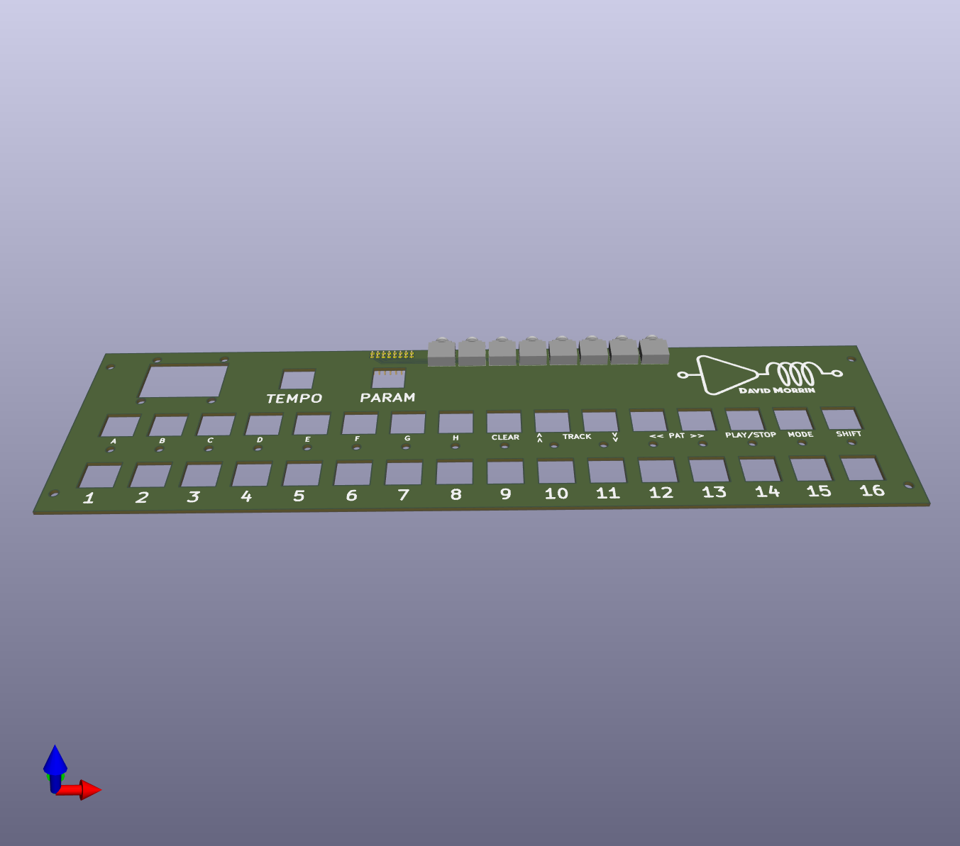 |
The application is designed as a standalone, embedded instrument. It functions as an 8-track step sequencer with support for 96 PPQN high-resolution timing, pattern chaining (Song Mode), per-track swing, real-time performance triggers, and visual feedback via an I2C OLED display with scrolling track views.
The codebase adopts a modular architecture separating data, presentation, and hardware control. The source code located in src/ is organized into the following domains:
Model (src/Model/)
This directory contains the core logic and data structures. It serves as the single source of truth for the application, managing the Pattern Pool, the Playlist (Song Mode), Swing parameters, and the Undo buffer. The Model is decoupled from hardware; it does not know if it is being driven by a clock or edited by a keyboard.
View (src/View/)
This directory handles all visual output.
DisplayManager: Observes the Model and renders the interface (Grid, Transport, Headers) to the OLED. It handles viewport scrolling to display 8 tracks on a 4-track height screen.StepLeds: Manages the 16-step LED array via SPI shift registers.
The view layer includes internal throttling logic to maintain a consistent frame rate without blocking the audio/timing threads.Controller (src/Controller/)
This directory manages user input and state routing. The UIManager aggregates inputs from multiple hardware sources:
KeyMatrix, a custom driver for scanning the 4x8 diode array.AnalogInput, which provides hysteresis and signal smoothing for potentiometers.Inputs are translated into abstract InputCommands (e.g., CMD_TRANSPORT_TOGGLE), decoupling the physical control method from the internal application logic.
Engine (src/Engine/)
This directory handles real-time operations.
ClockEngine: A 96 PPQN (Pulses Per Quarter Note) interrupt-driven engine. It calculates micro-timing for Swing and groove effects, offering 24 "ticks" per 16th-note step.OutputDriver: Abstraction layer for the physical hardware. It converts track bitmasks into GPIO signals using high-precision interrupt timers.Configuration (src/Config.h)
A global header file defining build-time constraints, including track count, pattern limits, pin mappings, and signal polarity.
The system is designed to be extensible. Developers looking to expand functionality should consider the following architectural patterns:
Current pattern data is stored in volatile RAM and is lost upon power cycle. The Teensy 4.1 includes a native micro-SD card slot. Future development should implement a PersistenceManager class. This component should:
SequencerModel data structures (Pattern Pool and Playlist) into a binary or JSON format.UIManager to allow loading and saving of projects.The system timing is based on a standard 4/4 time signature where a "beat" represents a quarter note.
The engine runs at 96 PPQN resolution. The interval $T$ (milliseconds per tick) is calculated as:
$$T = \frac{60,000}{BPM \times 96}$$
For a standard trigger pulse width of 15ms, the system manages overlapping triggers via a pulse-counter in the interrupt service routine.
| Qty | Value | Footprint | References |
|---|---|---|---|
| 32 | 1N4148 | project_footprints:D_DO-35_SOD27_P7.62mm_Horizontal | D35, D36, D37, D38, D39, D40, D41, D42, D43, D44, D45, D46, D47, D48, D49, D50 +16 |
| 32 | CherryMX | project_footprints:CherryMX_1.00u | SW1, SW2, SW10, SW11, SW12, SW13, SW14, SW15, SW16, SW17, SW18, SW19, SW20, SW21, SW22, SW23 +16 |
| 25 | 330 | project_footprints:R_Axial_DIN0207_L6.3mm_D2.5mm_P10.16mm_Horizontal | R3, R10, R11, R12, R13, R14, R15, R16, R17, R18, R20, R22, R23, R25, R26, R29 +9 |
| 18 | LED | project_footprints:LED_D3.0mm | D1, D2, D3, D4, D5, D6, D7, D10, D11, D12, D13, D14, D15, D16, D19, D20 +2 |
| 16 | 1N5817 | project_footprints:D_DO-15_P10.16mm_Horizontal | D17, D18, D21, D22, D23, D24, D25, D26, D27, D28, D29, D30, D31, D32, D33, D34 |
| 9 | 1k | project_footprints:R_Axial_DIN0207_L6.3mm_D2.5mm_P10.16mm_Horizontal | R19, R21, R24, R27, R28, R33, R34, R35, R36 |
| 3 | 100n | project_footprints:C_Disc_D5.0mm_W2.5mm_P2.50mm | C2, C3, C4 |
| 2 | 100k | project_footprints:Potentiometer_Bourns_PTV09A-1_Single_Vertical | RV1, RV2 |
| 2 | 4k7 | project_footprints:R_Axial_DIN0207_L6.3mm_D2.5mm_P10.16mm_Horizontal | R1, R2 |
| 2 | 74HC595 | project_footprints:DIP-16_W7.62mm | U2, U3 |
| 1 | 100u | project_footprints:CP_Radial_D5.0mm_P2.50mm | C1 |
| 1 | 3V3 | project_footprints:TestPoint_Keystone_5000-5004_Miniature | TP2 |
| 1 | 5V | project_footprints:TestPoint_Keystone_5000-5004_Miniature | TP1 |
| 1 | 74HCT245 | project_footprints:DIP-20_W7.62mm | U4 |
| 1 | EXT_PWR | project_footprints:PinHeader_1x02_P2.54mm_Vertical | J4 |
| 1 | GND | project_footprints:TestPoint_Keystone_5000-5004_Miniature | TP3 |
| 1 | Output | project_footprints:PinHeader_2x08_P2.54mm_Vertical | J2 |
| 1 | SH1106 Screen | project_footprints:PinHeader_1x04_P2.54mm_Vertical | J1 |
| 1 | Teensy4.1 | project_footprints:Teensy41 | U1 |
| 1 | USB_HOST | project_footprints:PinHeader_1x05_P2.54mm_Vertical | J3 |
dwmorrin/teensy-step-sequencer
hardware-based step sequencer using the Teensy 4.1 microcontroller

brianamos1/DuotrigesimalWS2811
A board for driving 32 strings of pixels from a Teensy 4.1. Similar to the OctoWS2811, but with 32 outputs.


Sutthiphong-H/project-flip-disc
FlipDisc Project was made for education of Project. Chadsadakorn Piriyasiriphan Jadesalit Suriyanimitsuk Sutthiphong Hongkham

Windfisch/midikraken
A open source, open hardware up-to-16x USB-MIDI-interface for around 15 bucks in its smallest configuration.


It measures 340 × 100 mm and has 2 copper layers, 1.6 mm thick.
151 parts, built around the 74HCT245, TEENSY 4.1 and 74HC595. The full list of its parts is on this page, with links to each part's symbol and footprint where PCBKit's library has them.
From the dwmorrin/teensy-step-sequencer repository on GitHub, at the commit this page was made from: the board is hardware/teensy-step-sequencer.kicad_pcb and its schematic hardware/teensy-step-sequencer.kicad_sch. PCBKit opens the board in the browser, with nothing to install.
Its repository states no licence, so its author keeps all rights: ask dwmorrin before reusing the design.