2 layers109.2 × 95.3 mm
 yeataro/LensRotaryDecoder1
Lens rotary decoder
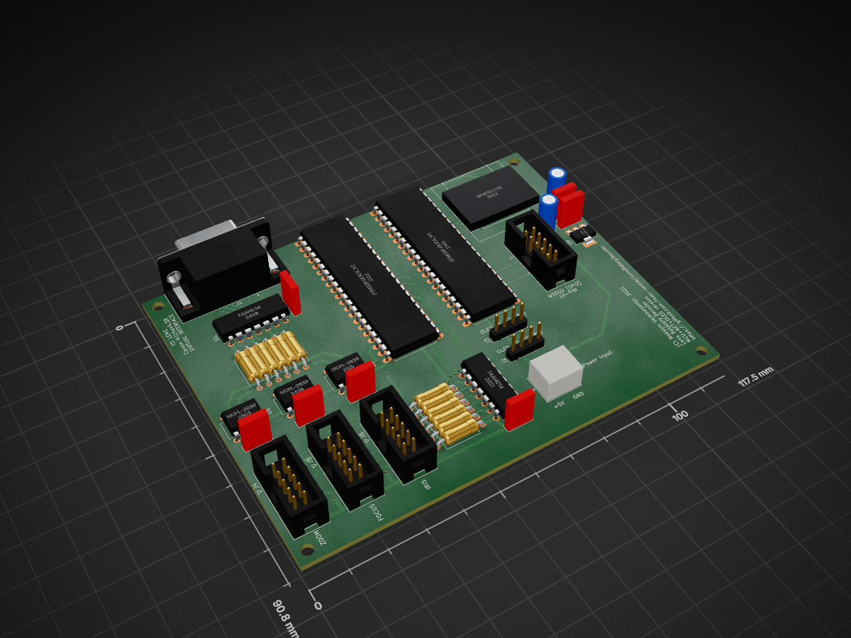
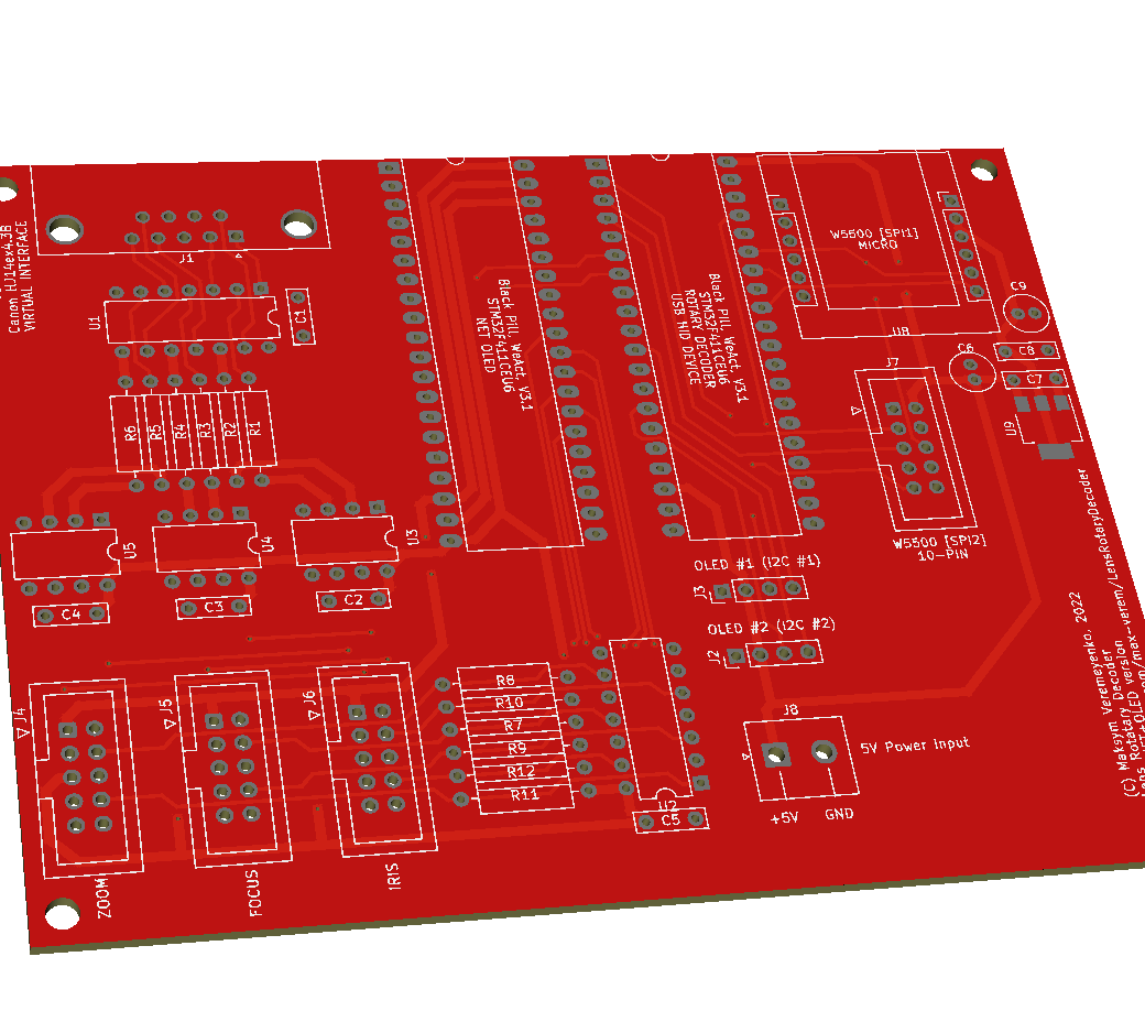
MCU NET OLED is an open-source printed circuit board by yeataro, from the yeataro/LensRotaryDecoder repository on GitHub. It is a 2-layer board of 117.5 × 90.8 mm with 42 parts on 119 nets, routed with 557 tracks and 29 vias.
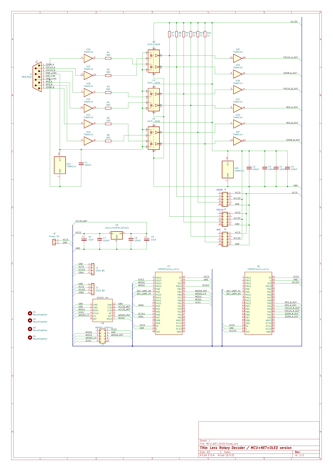
It is built around the HCPL2630M and 74AHC14D. Its parts include 12 resistors, 9 capacitors, 9 ICs and 8 connectors. It belongs with the lEDs and displays boards and the STM32 boards of this library.


This version cover both cases:
| Qty | Value | Footprint | References |
|---|---|---|---|
| 7 | 100nF | Capacitor_THT:C_Rect_L7.0mm_W2.0mm_P5.00mm | C1, C2, C3, C4, C5, C7, C8 |
| 6 | 1k | Resistor_THT:R_Axial_DIN0309_L9.0mm_D3.2mm_P12.70mm_Horizontal | R7, R8, R9, R10, R11, R12 |
| 6 | 360 | Resistor_THT:R_Axial_DIN0309_L9.0mm_D3.2mm_P12.70mm_Horizontal | R1, R2, R3, R4, R5, R6 |
| 4 | MountingHole | MountingHole:MountingHole_3.2mm_M3 | H1, H2, H3, H4 |
| 3 | Conn_02x05_Odd_Even | Connector_IDC:IDC-Header_2x05_P2.54mm_Vertical | J4, J5, J6 |
| 3 | HCPL-2630 | Package_DIP:DIP-8_W7.62mm | U3, U4, U5 |
| 2 | 10uF | Capacitor_THT:C_Radial_D5.0mm_H11.0mm_P2.00mm | C6, C9 |
| 2 | 74AHC14 | Package_DIP:DIP-14_W7.62mm | U1, U2 |
| 2 | STM32F4x1Cx_v2.0+ | Package_DIP:DIP-40_W15.24mm_LongPads | U6, U7 |
| 1 | DB9_Male | Connector_Dsub:DSUB-9_Male_Horizontal_P2.77x2.84mm_EdgePinOffset7.70mm_Housed_MountingHolesOffset9.12mm | J1 |
| 1 | LD1117S33TR_SOT223 | Package_TO_SOT_SMD:SOT-223-3_TabPin2 | U9 |
| 1 | OLED #1 | Connector_PinHeader_2.54mm:PinHeader_1x04_P2.54mm_Vertical | J2 |
| 1 | OLED #2 | Connector_PinHeader_2.54mm:PinHeader_1x04_P2.54mm_Vertical | J3 |
| 1 | Power 5V | Connector_JST:JST_NV_B02P-NV_1x02_P5.00mm_Vertical | J8 |
| 1 | W5500 (10Pins) | Connector_IDC:IDC-Header_2x05_P2.54mm_Vertical | J7 |
| 1 | W5500 lite | LensRotaryDecoder:W5500 | U8 |


Windfisch/midikraken
A open source, open hardware up-to-16x USB-MIDI-interface for around 15 bucks in its smallest configuration.

JhonVelasquez/Embedded_system_Synchronize_Plant
Project of a embedded system that synchronizes signals in a plant. There is electronic (PCB) and software design (FreeRTOS for STM32F7).

tioluwanimofe/neocera-test-junior-project-2024_2025
report for junior design project class

polpo/picogus
Emulation of ISA sound cards and CD-ROM on Raspberry Pi Pico (GUS, SB/Adlib, MPU-401, Tandy, CMS, Panasonic CD-ROM) with USB mouse/joystick support


RobertPHeller/RPi-RRCircuits
A collection of circuit designs for various MCUs, not just Raspberry Pis relating to Model Railroading
It measures 117.5 × 90.8 mm and has 2 copper layers, 1.6 mm thick.
42 parts, built around the HCPL2630M and 74AHC14D. The full list of its parts is on this page, with links to each part's symbol and footprint where PCBKit's library has them.
From the yeataro/LensRotaryDecoder repository on GitHub, at the commit this page was made from: the board is HW/MCU_NET_OLED/MCU_NET_OLED.kicad_pcb and its schematic HW/Camera_Lens_Cable/Camera_Lens_Cable.kicad_sch. PCBKit opens the board in the browser, with nothing to install.
Its repository states no licence, so its author keeps all rights: ask yeataro before reusing the design.