
2 layers117.5 × 90.8 mm
 yeataro/LensRotaryDecoder1
Lens rotary decoder
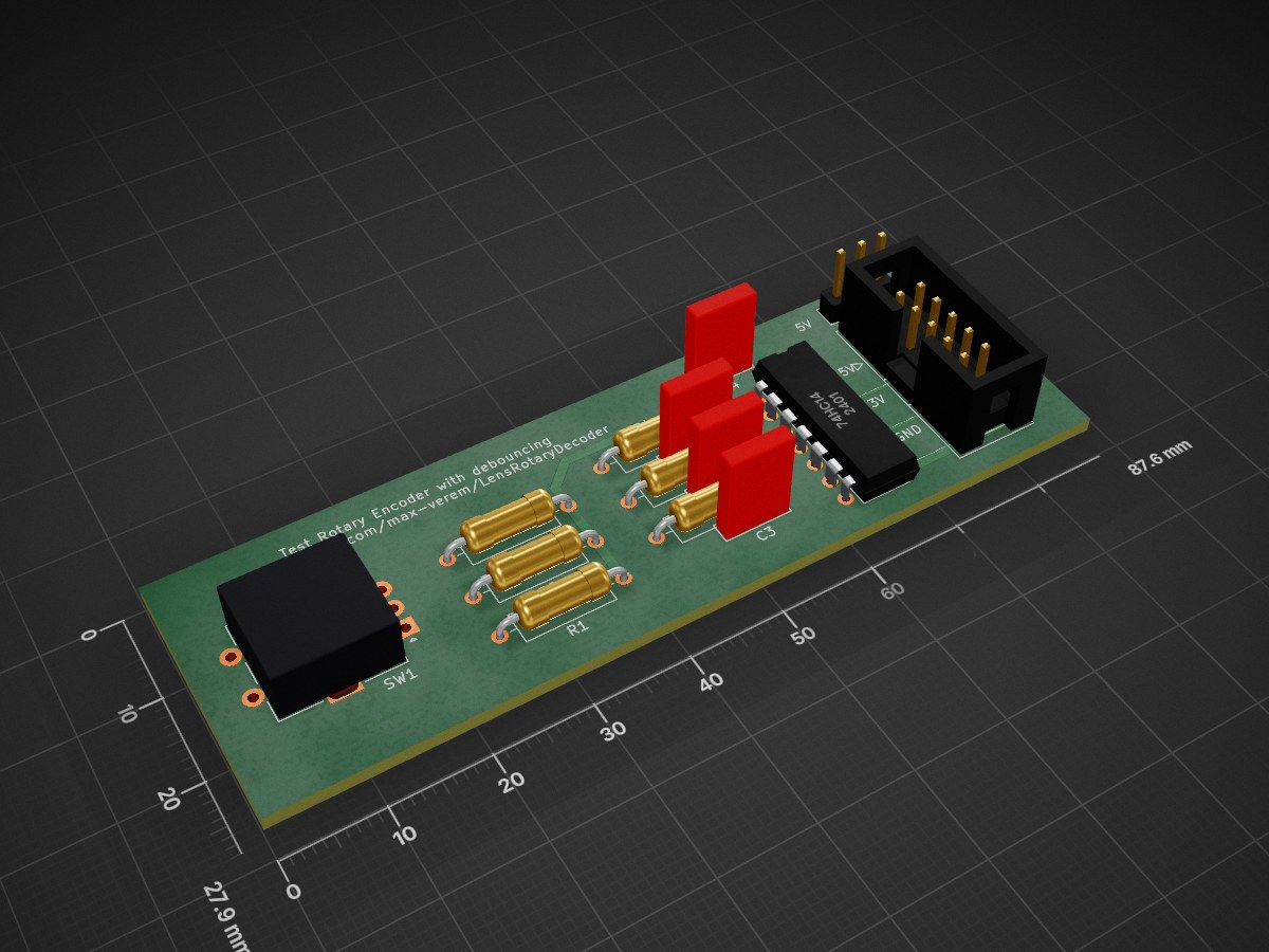
Test Rotary Encoder is an open-source printed circuit board by yeataro, from the yeataro/LensRotaryDecoder repository on GitHub. It is a 2-layer board of 87.6 × 27.9 mm with 14 parts on 20 nets, routed with 84 tracks and 0 vias.
It is built around the 74HC14. Its parts include 6 resistors, 4 capacitors, 1 IC, 1 connector and 1 switch.
This version cover both cases:
| Qty | Value | Footprint | References |
|---|---|---|---|
| 6 | 10K | Resistor_THT:R_Axial_DIN0309_L9.0mm_D3.2mm_P12.70mm_Horizontal | R1, R2, R3, R4, R5, R6 |
| 4 | 100nF | Capacitor_THT:C_Rect_L7.0mm_W2.0mm_P5.00mm | C1, C2, C3, C4 |
| 1 | 74HC14 | Package_DIP:DIP-14_W7.62mm | U1 |
| 1 | Conn_02x05_Odd_Even | Connector_IDC:IDC-Header_2x05_P2.54mm_Vertical | J1 |
| 1 | Jumper_3_Bridged12 | Connector_PinHeader_2.54mm:PinHeader_1x03_P2.54mm_Vertical | JP1 |
| 1 | RotaryEncoder_Switch | Rotary_Encoder:RotaryEncoder_Alps_EC11E-Switch_Vertical_H20mm | SW1 |


BlueSCSI/BlueSCSI-v2
BlueSCSI v2/Ultra - an open source, open hardware, SCSI emulator using the Pi Pico PR2040 and Pico 2 RP2350

keirf/pcb-projects
The old Kickstart switcher documentation is here.

anyshake/explorer
🌏 Detecting seismic wave using 3 geophones and 3-axis accelerometer, pack & send data to AnyShake Observer over RS232 / RS485 serial.

nicolacimmino/PLC-14500
Retro trainer board based on the MC14500 1-bit ICU. The project is OSHW certified and a ready to assemble kit is available on Tindie.


transistorfet/computie
A collection of 68k computer projects, including a unix-like operating system written in C that runs on them

sbstnh/programmable_precision_resistor
A SCPI programmable precision resistor

It measures 87.6 × 27.9 mm and has 2 copper layers, 1.6 mm thick.
14 parts, built around the 74HC14. The full list of its parts is on this page, with links to each part's symbol and footprint where PCBKit's library has them.
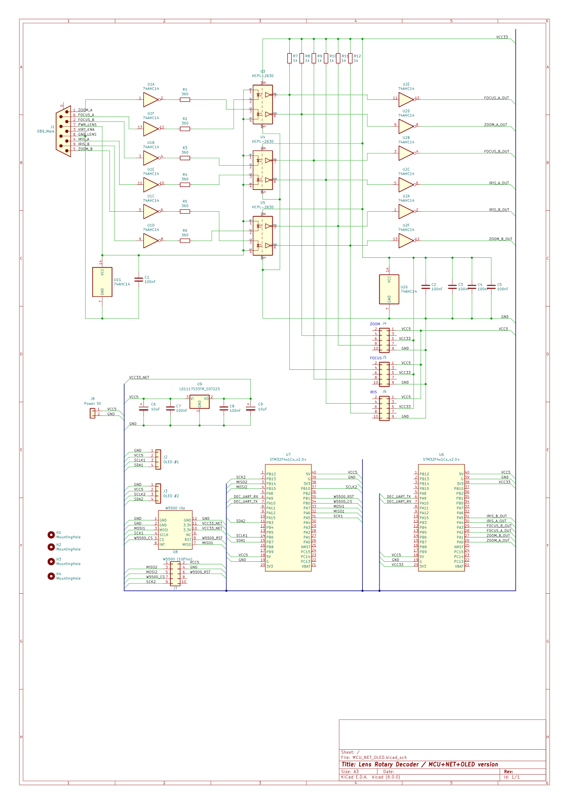
From the yeataro/LensRotaryDecoder repository on GitHub, at the commit this page was made from: the board is HW/Test_Rotary_Encoder/Test_Rotary_Encoder.kicad_pcb and its schematic HW/Camera_Lens_Cable/Camera_Lens_Cable.kicad_sch. PCBKit opens the board in the browser, with nothing to install.
Its repository states no licence, so its author keeps all rights: ask yeataro before reusing the design.