4 layers60 × 60 mm

 vodjan/uv-dosimeter
Wearable device for measuring UV irradiance with multiplatform companion app with dose warnings based on Fitzpatrick phototypes.
AOL PD 2 is an open-source printed circuit board by vodjan, from the vodjan/uv-dosimeter repository on GitHub. It is a 2-layer board of 50 × 25 mm with 33 parts on 32 nets, routed with 265 tracks and 9 vias.
It is built around the TLV9064ID, BPW34 and MBR120VLSFT1G-TP. Its parts include 12 resistors, 8 capacitors, 6 diodes, 3 ICs and 1 connector. It belongs with the ESP32 and RISC-V boards of this library.


Wearable device for measuring UV irradiance with multiplatform companion app with dose warnings based on Fitzpatrick phototypes.
This repository is a mirror of Jan Vodstrčil's and Ondřej Pokovič's project made for the Applied Optoelectronics in Medicine subject at CTU FEE. The source repository can be found at CTU FEE's GitLab. The README, docs/ and licenses (see License) have been updated for this public mirror.
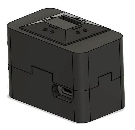
Measures UV irradiance with an ML8511, estimates the angle between the sensor face and the sun from four edge-mounted BPW34 photodiodes, and divides the reading by cos(theta) to recover the irradiance that a sun-facing sensor would have measured. The corrected value is integrated over time into an erythema-weighted dose and compared against the minimal erythema dose for the wearer's skin phototype.
Custom KiCad PCB, ESP32-H2 firmware, and a Flet/Bleak companion app.
| MCU | ESP32-H2-Zero (RISC-V, BLE) |
| UV sensor | ML8511, analog output |
| Angle sensing | 4x BPW34 into TLV9064 transimpedance amplifiers |
| ADC | 12-bit, 11 dB attenuation, factory-calibrated read |
| Sample rate | 2 Hz |
| Offline storage | 2048 records at 10 s intervals (12 KB LittleFS, ~5.7 h) |
| Link | BLE GATT, notify-only |
| App | Flet + Bleak (Linux / Windows / macOS) |
| Path | Contents |
|---|---|
| firmware/ | Sensor read-out, BLE GATT server, flash ring buffer |
| app/ | Companion app: BLE client, dose tracker, UI |
| hardware/ | KiCad 9 schematic, PCB, custom symbol and footprint libraries |
| math/ | MATLAB derivation of the erythema calibration coefficient |
A flat sensor tilted away from the sun by angle theta reads E * cos(theta) instead of E.
On a wrist the tilt is arbitrary and changes constantly, so theta has to be measured rather than assumed.
The four BPW34 diodes are tilted 20 deg outward from the PCB normal, one per edge.
Their normals are (+/-sin20, 0, cos20) and (0, +/-sin20, cos20).
Weighting each normal by its photocurrent and summing approximates the sun direction:
s          = ( (R - L) * sin20,  (T - B) * sin20,  (L + R + T + B) * cos20 )
cos(theta) = s_z / |s|
Implemented in sensors.cpp with sin20 = 0.342, cos20 = 0.940.
Two consequences of the form of the expression:
s_x and s_y, and s_z appears in both numerator and denominator, so PD_DARK_OFFSET only needs to be approximately right.|s| is undefined at zero illumination.
The implementation returns cos(theta) = 1 when the magnitude is zero.Below cos(theta) = 0.05 the division is ill-conditioned, so uvCorrected is set to NaN rather than a large number.
This propagates through the BLE packet and is treated as zero irradiance by the dose tracker.
Two-layer PCB with ground pours on both copper layers and components populated on both sides, built around the ESP32-H2-Zero module and designed in KiCad 9. Schematic: AOL_PD_2.kicad_sch.
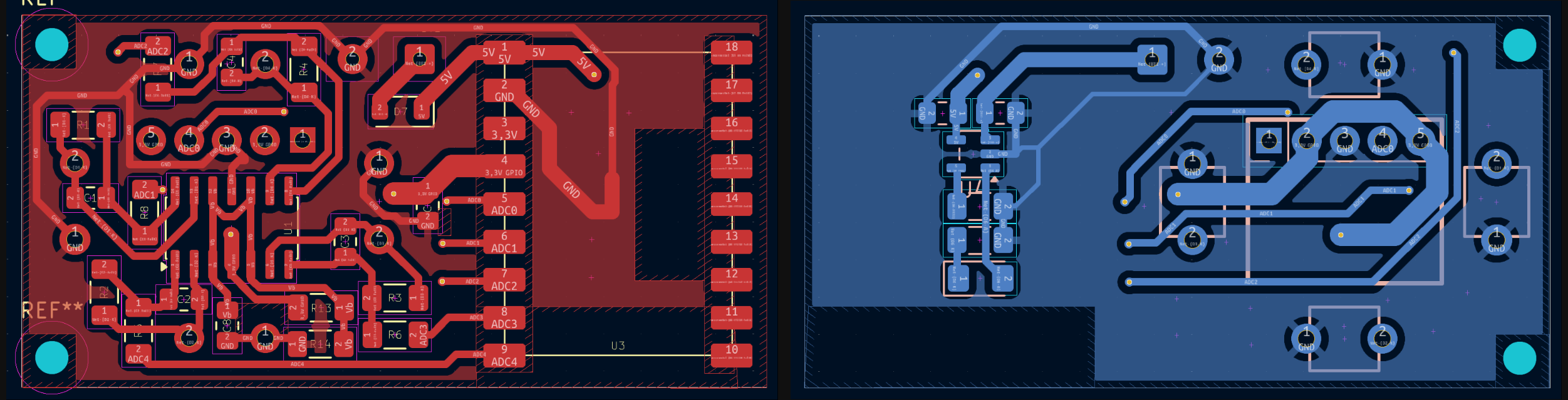
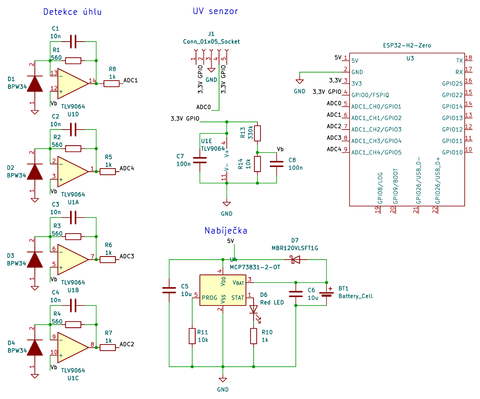
| Signal | GPIO | Schematic net |
|---|---|---|
UV_EN | 0 | 3,3V GPIO |
UV | 1 | ADC0 |
LEFT | 2 | ADC1 |
BOTTOM | 3 | ADC2 |
RIGHT | 4 | ADC3 |
TOP | 5 | ADC4 |
GPIO0 drives both the ML8511 EN pin and the divider that biases the photodiode amplifiers, so a single digitalWrite(PIN_UV_EN, HIGH) in setup() brings up the entire analog front end.
ML8511 transfer function.
Linear, 0.99 V at 0 mW/cm^2 and 2.8 V at 15 mW/cm^2, giving E = max((V - 0.99) * 15 / 1.81, 0).
Photodiode channels are inverted.
The TLV9064 stages are inverting transimpedance amplifiers with the non-inverting input biased to Vb ~= 97 mV, generated by a 330k/10k divider off GPIO0 and buffered by a fifth op-amp section.
Increasing photocurrent pulls the output toward GND, so a lower ADC count means more light.
Firmware converts with light = max(0, PD_DARK_OFFSET - raw).
The UV channel needs the calibrated ADC read.
ESP32 ADC non-linearity near the bottom of the range causes analogRead() to underestimate voltages around the ML8511's 0.99 V floor, which clipped all low readings to zero.
analogReadMilliVolts() applies the factory calibration and corrects this.
The raw count is still reported over BLE for diagnostics.
PD_DARK_OFFSET in config.h is per-board: cover all four diodes, read the peak count, add margin.
Default 110.
PlatformIO with the pioarduino platform fork, which supplies arduino-esp32 3.x (ESP-IDF 5.x) for the H2.
cd firmware
pio run -t upload && pio device monitor
On Linux, install 99-platformio-udev.rules first.
The main loop samples all five channels, then either notifies the connected client or appends to the ring buffer, and sleeps 500 ms.
Power management.
esp_pm_configure() sets 96 MHz max / 32 MHz min with automatic light sleep, so FreeRTOS sleeps during delay() while the BLE controller schedules its own wake-ups for connection events.
This avoids calling esp_light_sleep_start() manually against running BLE tasks.
Requires arduino-esp32 3.x, which enables CONFIG_PM_ENABLE and CONFIG_FREERTOS_USE_TICKLESS_IDLE by default; on 2.x the call fails silently and delay() behaves normally.
Offline buffer.
While disconnected, one {dt_s, uvCorrected} record is written every 10 s to a LittleFS-backed ring buffer, with head/tail/count indices mirrored in NVS so the buffer survives reset.
Records are 6 bytes; 2048 of them cover about 5.7 hours.
clear() resets the logical indices without erasing file data, and iteration is deliberately not invalidated by it.
Advertises as UV Sensor with the service UUID in the advertisement payload; the app connects by service UUID rather than by name.
| UUID | Properties | |
|---|---|---|
| Service | 4fafc201-1fb5-459e-8fcc-c5c9c331914b | |
| Live data | beb5483e-36e1-4688-b7f5-ea07361b26a8 | notify |
| History | d3e52b10-7a4f-4c8d-a9e6-2f1b8c3d5e70 | notify |
Live notification, 22 bytes packed little-endian (struct.unpack('<HfffHHHH', data)):
| Offset | Type | Field |
|---|---|---|
| 0 | uint16 | rawUv |
| 2 | float | uvMwCm2 |
| 6 | float | uvCorrected (NaN when cosTheta < 0.05) |
| 10 | float | cosTheta |
| 14 | uint16 x4 | rawLeft, rawBottom, rawRight, rawTop |
History transfer, on the second characteristic:
<Hf), paced 20 ms apart to avoid overflowing the stack's notify queue.0x00 byte.
The client treats any payload whose length is not 6 bytes as the terminator.While a client is connected the buffer is not written to, and the record timer is reset on every live packet so the first offline record after disconnect carries a correct dt_s.
cd app
pip install -r requirements.txt
python main.py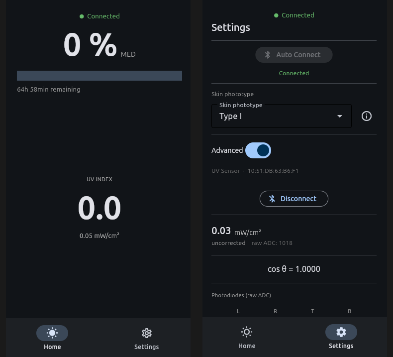
Home shows UV index, angle-corrected irradiance, and accumulated dose as a percentage of MED. The progress bar transitions green to orange at 50 % and to red at 80 %, with a subtitle estimating time remaining at the current rate. Dose is persisted to client storage along with the date it was accumulated, and restored on launch only if that date is today, so a new calendar day starts from zero.
Settings holds the connect button, a last-sync timestamp, and the Fitzpatrick phototype selector (I-VI, with a reference card sourced from NCBI StatPearls; changing the phototype resets the dose).
An "Advanced" switch reveals a developer panel, hidden by default, exposing the five raw ADC counts, cos(theta), uncorrected irradiance, and manual scan/connect/disconnect/reset controls.
On connect, buffered history is replayed through update_historical() before live streaming starts, and a snack bar reports how much offline time was synced.
A dose reset performed while disconnected sets a persisted pending_reset flag that suppresses the next replay.
K = 0.001719 is computed in sem_project.m as the ratio of two integrals over the ASTM G-173 solar spectrum: irradiance weighted by the McKinlay-Diffey erythema action spectrum, divided by irradiance weighted by the ML8511's spectral response.
It therefore converts what this specific sensor measures into what skin responds to.
Per sample, with the factor 10 converting mW/cm^2 to W/m^2:
E_ery [W/m^2] = uvCorrected * 10 * K
dose  [J/m^2] = sum(E_ery * dt)
UVI           = E_ery * 40
Dose is compared against the lower bound of the MED range for each phototype (200 / 250 / 300 / 450 / 600 / 1000 J/m^2 for types I-VI). NaN samples are treated as zero irradiance, and accumulation pauses on disconnect rather than integrating across the gap.
Working prototype; firmware and app function end to end.
Toolchain notes for the original ESP8266 prototype are kept in docs/esp8266-rtos-sdk-linux.md.
Copyright (C) 2026 Jan Vodstrčil and Ondřej Pokovič.
Different parts of this project are released under different reciprocal licenses, each carrying its full text in the directory it applies to.
| Path | License |
|---|---|
| firmware/ | GPL-3.0-or-later |
| app/ | GPL-3.0-or-later |
| hardware/ | CERN-OHL-S-2.0 |
| math/ | CC-BY-SA-4.0 |
| docs/ | CC-BY-SA-4.0 |
A file's license is determined by the directory it lives in.
math/astmg173.xls is third-party ASTM G-173 reference spectrum data distributed by NREL and is not covered by these terms.
See LICENSE for the full breakdown.
| Qty | Value | Footprint | References |
|---|---|---|---|
| 5 | 1k | Resistor_SMD:R_1206_3216Metric_Pad1.30x1.75mm_HandSolder | R5, R6, R7, R8, R10 |
| 4 | 10n | Capacitor_SMD:C_0805_2012Metric_Pad1.18x1.45mm_HandSolder | C1, C2, C3, C4 |
| 4 | 560 | Resistor_SMD:R_1206_3216Metric_Pad1.30x1.75mm_HandSolder | R1, R2, R3, R4 |
| 4 | BPW34 | KiCad:BPW34 | D1, D2, D3, D4 |
| 2 | 100n | Capacitor_SMD:C_0805_2012Metric_Pad1.18x1.45mm_HandSolder | C7, C8 |
| 2 | 10k | Resistor_SMD:R_1206_3216Metric_Pad1.30x1.75mm_HandSolder | R11, R14 |
| 2 | 10u | Capacitor_SMD:C_0805_2012Metric_Pad1.18x1.45mm_HandSolder | C5, C6 |
| 1 | 330k | Resistor_SMD:R_1206_3216Metric_Pad1.30x1.75mm_HandSolder | R13 |
| 1 | Battery_Cell | Connector_Wire:SolderWire-0.25sqmm_1x02_P4.5mm_D0.65mm_OD2mm | BT1 |
| 1 | Conn_01x05_Socket | Connector_PinHeader_2.54mm:PinHeader_1x05_P2.54mm_Vertical | J1 |
| 1 | ESP32-H2-Zero | Moje_wearable:Waveshare_ESP32-H2-Zero | U3 |
| 1 | MBR120VLSFT1G | Diode_SMD:D_SOD-123F | D7 |
| 1 | MCP73831-2-OT | Package_TO_SOT_SMD:SOT-23-5 | U4 |
| 1 | Red LED | LED_SMD:LED_1206_3216Metric_Pad1.42x1.75mm_HandSolder | D6 |
| 1 | TLV9064 | Package_SO:SOIC-14_3.9x8.7mm_P1.27mm | U1 |
The 31 most common of 33 parts.
It measures 50 × 25 mm and has 2 copper layers, 1.6 mm thick.
33 parts, built around the TLV9064ID, BPW34 and MBR120VLSFT1G-TP. The full list of its parts is on this page, with links to each part's symbol and footprint where PCBKit's library has them.
From the vodjan/uv-dosimeter repository on GitHub, at the commit this page was made from: the board is hardware/AOL_PD_2.kicad_pcb and its schematic hardware/AOL_PD_2.kicad_sch. PCBKit opens the board in the browser, with nothing to install.
Its repository states no licence, so its author keeps all rights: ask vodjan before reusing the design.


Jed0vcela/Linear-CCD-camera-V1
Prototype of "scanning" camera using linar CCD sensor ILX555K


embedded-pro/e-foc-hardware
hardware to be used with https://github.com/embedded-pro/e-foc
