2 layers120 × 120 mm
Modular LED Controller V4
victovats/Modular_LED_Board
Modular PCB to supply power to and control LED strips, providing input for both 5V and 12V. For the Mars Rover of the Toronto Metropolitan Robotics Team
40 parts

 victovats/Modular_Relay_Board_PCB_TMR
Modular relay board designed for Toronto Metropolitan Robotics featuring 4 relay circuits that isolate high-voltage inputs from low-voltage control signals to prevent interference.
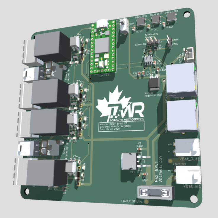
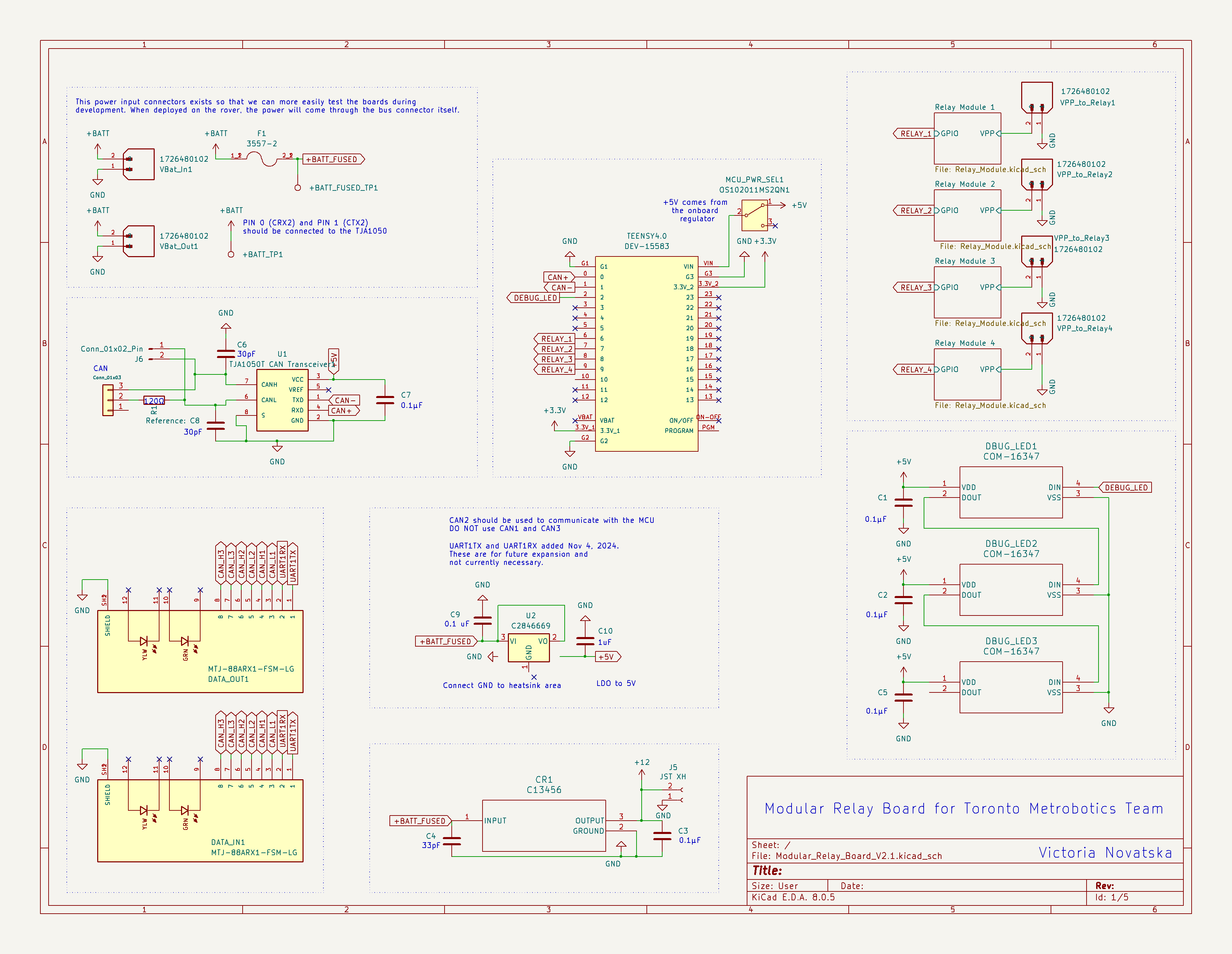
Modular Relay Board V2.1 is an open-source printed circuit board by victovats, from the victovats/Modular_Relay_Board_PCB_TMR repository on GitHub. It is a 2-layer board of 120 × 120 mm with 78 parts on 90 nets, routed with 476 tracks and 60 vias.
It is built around the BD450M5WFPJ-CZE2, CL21B104KBCNNNC and AZ943-1CH-12DE, with the KT-0805Y, LTV-816S-TA1-A and COM-16347 among its other parts. Its parts include 17 resistors, 10 capacitors, 8 diodes, 8 switches and 6 connectors. It belongs with the home automation and IoT boards of this library.


A 4 channel relay board made for the Toronto Metropolitan Robotics team for higher voltage inputs to be switched using the onboard Teensy 4.1 MCU. I have linked the 3D model below, and a high resolution pdf of the schematic can be found in the repository.
| Qty | Value | Footprint | References |
|---|---|---|---|
| 12 | 0805W8F1001T5E | LED_SMD:LED_0805_2012Metric_Pad1.15x1.40mm_HandSolder | R2, R3, R4, R5, R6, R7, R8, R9, R10, R11, R12, R13 |
| 6 | CL21B104KBCNNNC | Capacitor_SMD:C_0805_2012Metric_Pad1.18x1.45mm_HandSolder | C1, C2, C3, C5, C7, C9 |
| 4 | 0805W8F1003T5E (SMT业务专用) | LED_SMD:LED_0805_2012Metric_Pad1.15x1.40mm_HandSolder | R14, R15, R16, R17 |
| 4 | 1726480102 | TMR-25-1-1-0 Modular Control Board Template Footprints:MOLEX_1726480102 | VBat_In1, VBat_Out1, VPP_to_Relay1, VPP_to_Relay3 |
| 4 | 1757255 | connector:PHOENIX_1757255 | J1, J2, J3, J4 |
| 4 | 1N4007 | Diode_THT:D_DO-41_SOD81_P10.16mm_Horizontal | D2, D4, D6, D8 |
| 4 | 2N7002 | NPN:TRANS_2N7002 | Q1, Q2, Q3, Q4 |
| 4 | AZ943-1CH-12DE | Relay:AZ943-1CH_AMZ | K1, K2, K3, K4 |
| 4 | KT-0805Y | LED_SMD:LED_0805_2012Metric | D1, D3, D5, D7 |
| 4 | LTV-816S-TA1-A | Optocoupler:LTV-816S_LTO | K5, K6, K7, K8 |
| 3 | COM-16347 | TMR-25-1-1-0 Modular Control Board Template Footprints:COM-16347_SPK-M | DBUG_LED1, DBUG_LED2, DBUG_LED3 |
| 2 | 0805CG300J500NT | Capacitor_SMD:C_0805_2012Metric_Pad1.18x1.45mm_HandSolder | C6, C8 |
| 2 | 1726480102 | Right angle pwr con:172647-0102 | VPP_to_Relay2, VPP_to_Relay4 |
| 2 | MTJ-88ARX1-FSM-LG | TMR-25-1-1-0 Modular Control Board Template Footprints:ADAMTECH_MTJ-88ARX1-FSM-LG | DATA_IN1, DATA_OUT1 |
| 2 | TestPoint | TestPoint:TestPoint_Pad_D2.0mm | +BATT_FUSED_TP1, +BATT_TP1 |
| 1 | 0805W8F1200T5E | Resistor_SMD:R_0805_2012Metric_Pad1.20x1.40mm_HandSolder | R1 |
| 1 | 3557-2 | TMR-25-1-1-0 Modular Control Board Template Footprints:FUSE_3557-2 | F1 |
| 1 | C13456 | footprints:D2PAK_STM | CR1 |
| 1 | C2846669 | Package_TO_SOT_SMD:TO-252-4 | U2 |
| 1 | CC0805JRNPO9BN330 | Capacitor_SMD:C_0805_2012Metric_Pad1.18x1.45mm_HandSolder | C4 |
| 1 | CL21B105KAFNFNE | Capacitor_SMD:C_0805_2012Metric_Pad1.18x1.45mm_HandSolder | C10 |
| 1 | Conn_01x02_Pin | Connector_PinHeader_2.54mm:PinHeader_1x02_P2.54mm_Vertical | J6 |
| 1 | Conn_01x03 | Connector_PinHeader_2.54mm:PinHeader_1x03_P2.54mm_Vertical | TerminatingResistorSwitch1 |
| 1 | DEV-15583 | TMR-25-1-1-0 Modular Control Board Template Footprints:MODULE_DEV-15583 | TEENSY4.0 |
| 1 | JST XH | Connector_JST:JST_XH_B2B-XH-A_1x02_P2.50mm_Vertical | J5 |
| 1 | LOGO | LOGO | G*** |
| 1 | OS102011MS2QN1 | TMR-25-1-1-0 Modular Control Board Template Footprints:OS102011MS2QN1 | MCU_PWR_SEL1 |
| 1 | TJA1050T CAN Transceiver1 | TJA1050:SOT96-1 | U1 |
The 74 most common of 78 parts.
victovats/Modular_LED_Board
Modular PCB to supply power to and control LED strips, providing input for both 5V and 12V. For the Mars Rover of the Toronto Metropolitan Robotics Team

Gamecard/k2-plus-cm5
K2 Plus CM5 – Creality K2 Plus mit Upstream-Klipper auf einem Raspberry Pi CM5


kulovac/tuner-pedal
Source for my tuner pedal project from algorithm design to PCB implementation

lightningspore/shieldsigner-dev
ShieldSigner Luckfox carrier: KiCad design, smartcard docs, reproducible build tools and HTMX knowledge site


WasabiMushyPeas/coilSafetyCircuit
An electromagnet safety circuit for Dr. Biedermann's Lab.

It measures 120 × 120 mm and has 2 copper layers, 1.6 mm thick.
78 parts, built around the BD450M5WFPJ-CZE2, CL21B104KBCNNNC, AZ943-1CH-12DE and KT-0805Y. The full list of its parts is on this page, with links to each part's symbol and footprint where PCBKit's library has them.
From the victovats/Modular_Relay_Board_PCB_TMR repository on GitHub, at the commit this page was made from: the board is Modular_Relay_Board/Modular_Relay_Board_V2.1.kicad_pcb and its schematic Modular_Relay_Board/Modular_Relay_Board_V2.1.kicad_sch. PCBKit opens the board in the browser, with nothing to install.
Its repository states no licence, so its author keeps all rights: ask victovats before reusing the design.