
4 layers66 × 42 mm

Open hardware compute module with Allwinner A13 (ARM-A8 @1GHz), DDR3 (max 512MB) and expansions (USB, GPIO, WiFi, LCD, Audio)
Module is an open-source printed circuit board by vd-rd, from the vd-rd/sbc_allwinner_a13 repository on GitHub. It is a 4-layer board of 80 × 42 mm with 179 parts on 267 nets, routed with 4,355 tracks and 501 vias.
It is built around the A13, AP61100Z6 and W25Q128JVSIQ, with the AP2281-1WG, AXP209 and RTL8188CUS-GR among its other parts. Its parts include 84 capacitors, 40 resistors, 10 ICs, 6 inductors and 5 connectors. It belongs with the computers and single-board computers and radio and wireless boards of this library.


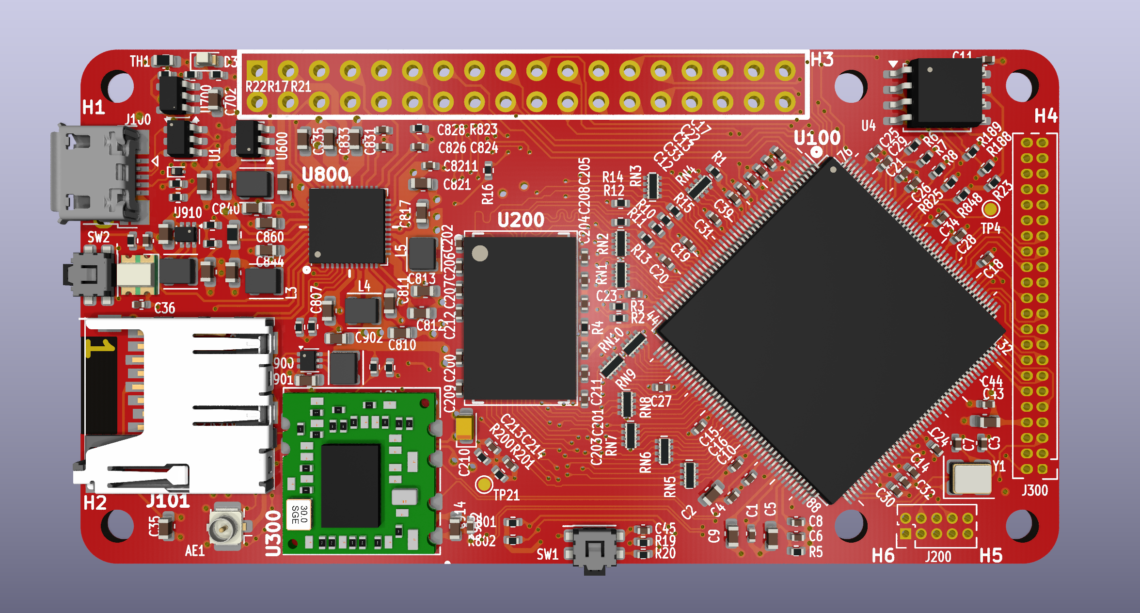
Board overview (draft): [TBD]
| Characteristic | Description |
|---|---|
| Dimensions | 80mm x 40mm |
| Processor | Allwinner A13 (ARM Cortex-A8 @ 1Ghz) |
| Oscillators | 24MHz main clock |
| RAM | DDR3 512MB max (8Gbit module) |
| Storage | microSD |
| USB | 1 microUSB OTG |
| Ethernet | N/A |
| WiFi/BT | RTL8188CUS module |
| LCD | Parallel interface 18bit |
| Expansions | 1xUART, 1xI2C, 1xSPI, 4xGPIO, Microphone, EarphoneOut |
| Supply | Power path between USB/ACIN/Battery, 5V max |
The board can be combined with several predefined capes that add functionality.
A13 features a few power rails:
The datasheet states that AVCC and VDD-DRAM must be present at all times (even standby). VDD-INT and VDD-CPU can't be tied together because VDD-CPU is DVS enabled.
A13 DRAM controller doesn't provide DDR-CS. On the memory side the pin is tied to GND. Memory tuning should be performed as described here
Build U-Boot and Linux kernel + rootFS - TBD
Flash to SDCard - TBD
You can find all necesary information to build or evaluate the module here:
Inspiration for this has been drawn from:
| Qty | Value | Footprint | References |
|---|---|---|---|
| 49 | 100nF | Capacitor_SMD:C_0402_1005Metric | C1, C10, C11, C12, C13, C14, C15, C16, C17, C18, C19, C20, C200, C201, C202, C203 +33 |
| 21 | 10uF | Capacitor_SMD:C_0603_1608Metric | C2, C9, C43, C601, C701, C702, C807, C810, C813, C817, C831, C833, C835, C839, C840, C843 +5 |
| 10 | 24 | Resistor_SMD:R_Array_Concave_4x0402 | RN1, RN2, RN3, RN4, RN5, RN6, RN7, RN8, RN9, RN10 |
| 10 | TestPoint | TestPoint:TestPoint_Pad_D1.0mm | TP2, TP3, TP4, TP5, TP6, TP14, TP15, TP16, TP17, TP21 |
| 9 | 2.2k | Resistor_SMD:R_0402_1005Metric | R9, R21, R188, R189, R200, R201, R801, R802, R804 |
| 8 | 24 | Resistor_SMD:R_0402_1005Metric | R2, R3, R10, R11, R12, R13, R14, R15 |
| 6 | 200k | Resistor_SMD:R_0402_1005Metric | R5, R19, R22, R23, R901, R911 |
| 6 | 4.7uF | Capacitor_SMD:C_0603_1608Metric | C5, C811, C812, C821, C844, C860 |
| 6 | MountingHole | MountingHole:MountingHole_2.7mm_M2.5_DIN965 | H1, H2, H3, H4, H5, H6 |
| 5 | 1uF | Capacitor_SMD:C_0402_1005Metric | C8, C36, C824, C826, C828 |
| 4 | 47k | Resistor_SMD:R_0402_1005Metric | R16, R20, R825, R848 |
| 3 | 180 | Resistor_SMD:R_0402_1005Metric | R6, R7, R8 |
| 3 | 4.7uH | Inductor_SMD:L_Wuerth_MAPI-2512 | L3, L4, L5 |
| 2 | 1uH | Inductor_SMD:L_Wuerth_MAPI-2510 | L1, L910 |
| 2 | 22pF | Capacitor_SMD:C_0402_1005Metric | C3, C7 |
| 2 | 240 | Resistor_SMD:R_0402_1005Metric | R1, R4 |
| 2 | 562k | Resistor_SMD:R_0402_1005Metric | R17, R602 |
| 2 | AP61100 | Package_TO_SOT_SMD:SOT-563 | U900, U910 |
| 2 | SW_Push | Button_Switch_SMD:SW_SPST_EVQP7C | SW1, SW2 |
| 1 | 100uF | Capacitor_Tantalum_SMD:CP_EIA-2012-15_AVX-P | C210 |
| 1 | 133k | Resistor_SMD:R_0402_1005Metric | R902 |
| 1 | 200K | Resistor_SMD:R_0402_1005Metric | R823 |
| 1 | 24MHz | Crystal:Crystal_SMD_3225-4Pin_3.2x2.5mm | Y1 |
| 1 | 30m | Resistor_SMD:R_0603_1608Metric | R18 |
| 1 | 4.7uH | Inductor_SMD:L_Wuerth_MAPI-2510 | L2 |
| 1 | 44.2k | Resistor_SMD:R_0402_1005Metric | R910 |
| 1 | 47K | Resistor_SMD:R_0402_1005Metric | R701 |
| 1 | 976k | Resistor_SMD:R_0402_1005Metric | R601 |
| 1 | A13 | allwinner:LQFP-176_20x20mm_P0.4mm | U100 |
| 1 | AP22811 | Package_TO_SOT_SMD:SOT-23-5 | U700 |
| 1 | AXP209 | Package_DFN_QFN:QFN-48-1EP_6x6mm_P0.4mm_EP4.2x4.2mm_ThermalVias | U800 |
| 1 | Antenna_Shield | Connector_Coaxial:U.FL_Hirose_U.FL-R-SMT-1_Vertical | AE1 |
| 1 | Conn_02x05_Odd_Even | Connector_PinHeader_1.27mm:PinHeader_2x05_P1.27mm_Vertical | J200 |
| 1 | Conn_02x18_Odd_Even | Connector_PinHeader_2.54mm:PinHeader_2x18_P2.54mm_Vertical | J1 |
| 1 | Conn_02x22_Odd_Even | Connector_PinHeader_1.27mm:PinHeader_2x22_P1.27mm_Vertical | J300 |
| 1 | DDR3L-x16 | winbond:BGA-96_9x14mm_P0.8mm | U200 |
| 1 | ESD9B5.0ST5G | Diode_SMD:D_SOD-923 | D2 |
| 1 | LED_BAGR | led:LED_RGB_Optosupply_OSTB0805C1E-A-0.8T | D4 |
| 1 | LED_Small | LED_SMD:LED_0603_1608Metric | D3 |
| 1 | MCP1640CH | Package_TO_SOT_SMD:SOT-23-6 | U600 |
| 1 | Micro_SD_Card_Det | gct:MEM20610118800A | J101 |
| 1 | RTL8188CUS | wifi:RTL8188CUS | U300 |
| 1 | Thermistor_NTC | Resistor_SMD:R_0603_1608Metric | TH1 |
| 1 | USBLC6-2P6 | Package_TO_SOT_SMD:SOT-23-6 | U1 |
| 1 | USB_B_Micro | Connector_USB:USB_Micro-B_Amphenol_10103594-0001LF_Horizontal | J100 |
| 1 | W25Q128JVS | Package_SO:SOIC-8_5.3x5.3mm_P1.27mm | U4 |

vd-rd/sbc_allwinner_D1
Open Hardware SBC with Allwinner D1 RISC-V CPU and 512MB DDR3 RAM


vd-rd/sbc_at91sam9g20
Open hardware SBC module based on AT91SAM9G20 @400MHz with 128MB RAM

omniframe-art/Omniframe-Hardware
Omniframe is an open source e-paper digital frame. This repository includes the source and fabrication files for the main and secondary boards for driving the 13.3" Monochrome e-ink display.


CameraNexus/sitina1
Open-source 35mm full-frame (36mm x 24mm) CCD mirror-less interchangable lens camera (MILC). The original goal of this project was to create a digital camera back to convert SLR cameras to DSLR cameras, but has since…

It measures 80 × 42 mm and has 4 copper layers, 0.95 mm thick.
179 parts, built around the A13, AP61100Z6, W25Q128JVSIQ and AP2281-1WG. The full list of its parts is on this page, with links to each part's symbol and footprint where PCBKit's library has them.
From the vd-rd/sbc_allwinner_a13 repository on GitHub, at the commit this page was made from: the board is hardware/module.kicad_pcb and its schematic hardware/cpu.kicad_sch. PCBKit opens the board in the browser, with nothing to install.
Its repository states no licence, so its author keeps all rights: ask vd-rd before reusing the design.