
4 layers80 × 42 mm
Module
vd-rd/sbc_allwinner_a13
Open hardware compute module with Allwinner A13 (ARM-A8 @1GHz), DDR3 (max 512MB) and expansions (USB, GPIO, WiFi, LCD, Audio)
179 parts38

Open SBC module based on Allwinner V3s processor
Module is an open-source printed circuit board by vd-rd, from the vd-rd/sbc_allwinner_v3s repository on GitHub. It is a 4-layer board of 66 × 42 mm with 171 parts on 193 nets, routed with 409 tracks and 112 vias.
It is built around the V3S, AP61100Z6 and PCA6408APW, with the W25Q128JVSIQ, AP2281-1WG and AXP209 among its other parts. Its parts include 86 capacitors, 35 resistors, 11 ICs, 6 connectors and 6 inductors. It belongs with the computers and single-board computers boards of this library.


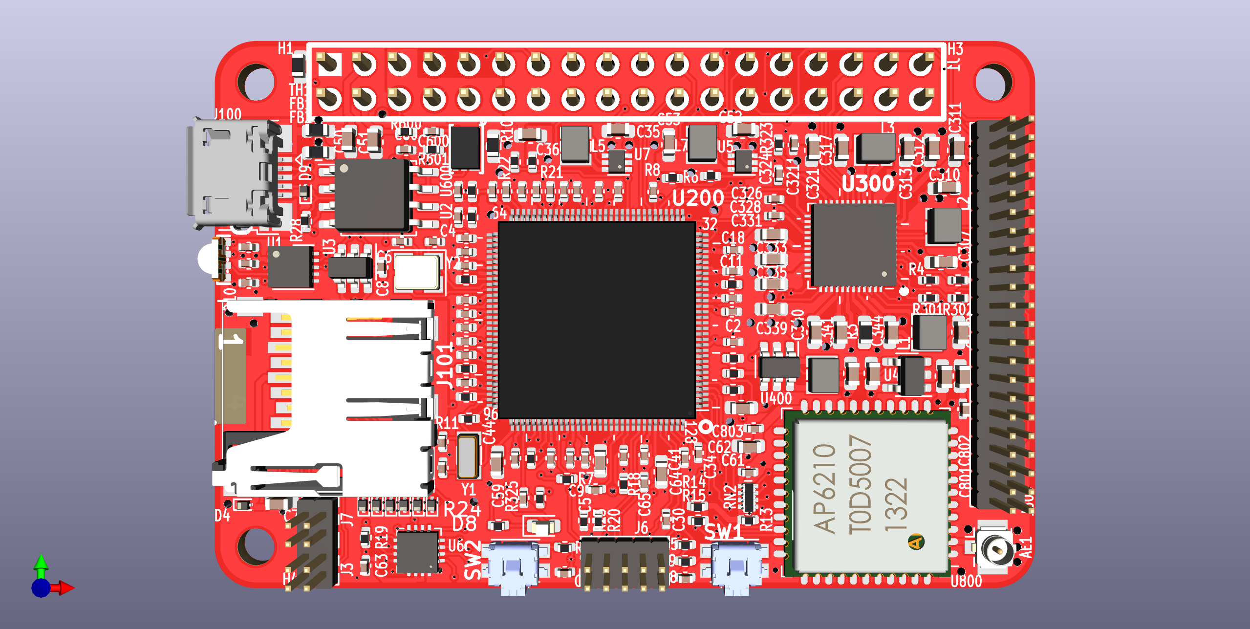
This board embeds a SIP (single core 1GHz Cortex-A7 with 64MB DDR2) with AXP203 PMIC, IO headers and microSD/eMMC storage.
Board overview (draft): [TBD]
| Characteristic | Description |
|---|---|
| Dimensions | 60mm x 40mm |
| Processor | Allwinner V3s Cortex-A7 @1GHz |
| Oscillators | 32.768kHz slow click, 24MHz main clock |
| RAM | 512Mb embedded DDR2 memory |
| Storage | SPI Flash/microSD |
| USB | 1 microUSB OTG |
| Ethernet | 10/100M PHY with pins on header |
| Supply | Power path between USB/Vin/Battery, 5V max |
The board features a number of connectors. They expose various buses for expansions:
The connectors are organized in consistent locations present on the other SBCs i have developed.
Check expansions section for example daughter cards with added functionality
The board has two boot strategies depending on component configuration. If the SPI flash memory is not used, the BROM uses the MicroSD as boot source and loads UBoot from there. If the SPI flash is populated, UBoot with a minimal Kernel and Busybox can be stored as recovery environment or main application.
Most of port D signals are mapped to the LCD connector. if LCD is not used they can be muxed as GPIO or other functions upon editing the DT overlay.
AXP203 is pin to pin compatible with the more popular AXP209, so they can be easily swapped.
Two different 1.2V rails are provided to the CPU. This is a deliberate decision to allow fixed CPU internal rail at 1.2V and provide DVFS cappability to 1.2V rail for CPU core.
All the signals on the headers, with their initial functions are detailed on the silkscreen on the bottom layer
The board schematic uses a Diodes AP9211 battery protection IC for safety protections when used toghether with a LiIon battery. If a battery pack with embedded protection and thermistor is used, TH1 and AP9211 can be left unpopulated.
The board can be combined with several predefined capes that add functionality.
You can find all necesary information to build or evaluate the module here:
| Qty | Value | Footprint | References |
|---|---|---|---|
| 34 | 1uF | Capacitor_SMD:C_0402_1005Metric | C103, C104, C106, C107, C108, C113, C114, C115, C116, C117, C118, C119, C120, C121, C122, C123 +18 |
| 20 | 10uF | Capacitor_SMD:C_0603_1608Metric | C43, C102, C111, C601, C701, C702, C807, C810, C813, C817, C831, C833, C835, C839, C840, C843 +4 |
| 18 | 100nF | Capacitor_SMD:C_0402_1005Metric | C37, C38, C44, C45, C80, C101, C105, C109, C112, C134, C135, C137, C138, C139, C904, C8211 +2 |
| 9 | TestPoint | TestPoint:TestPoint_Pad_D1.0mm | TP1, TP2, TP3, TP5, TP6, TP10, TP15, TP16, TP17 |
| 7 | 4.7uF | Capacitor_SMD:C_0603_1608Metric | C811, C812, C821, C844, C860, C903, C906 |
| 5 | 2.2k | Resistor_SMD:R_0402_1005Metric | R21, R102, R105, R106, R804 |
| 4 | 22pF | Capacitor_SMD:C_0402_1005Metric | C140, C141, C143, C144 |
| 4 | MountingHole | MountingHole:MountingHole_2.7mm_M2.5_DIN965 | H1, H2, H3, H4 |
| 3 | 180 | Resistor_SMD:R_0402_1005Metric | R6, R7, R8 |
| 3 | 200k | Resistor_SMD:R_0402_1005Metric | R101, R901, R911 |
| 3 | 33k | Resistor_SMD:R_0402_1005Metric | R903, R904, R905 |
| 3 | 4.7uH | Inductor_SMD:L_Wuerth_MAPI-2512 | L3, L4, L5 |
| 3 | 47k | Resistor_SMD:R_0402_1005Metric | R16, R825, R848 |
| 3 | Fiducial | Fiducial:Fiducial_0.75mm_Mask1.5mm | FID1, FID2, FID3 |
| 2 | 0 | Resistor_SMD:R_0402_1005Metric | R103, R104 |
| 2 | 1.8k | Resistor_SMD:R_0402_1005Metric | R801, R802 |
| 2 | 1uH | Inductor_SMD:L_Wuerth_MAPI-2510 | L1, L910 |
| 2 | AP61100 | Package_TO_SOT_SMD:SOT-563 | U900, U910 |
| 2 | LED_RGBA | led:rgb-1204 | D1, D8 |
| 2 | SW_Push | Button_Switch_SMD:SW_SPST_EVQP7C | SW1, SW2 |
| 1 | 100K | Resistor_SMD:R_0402_1005Metric | R701 |
| 1 | 100k | Resistor_SMD:R_0402_1005Metric | R19 |
| 1 | 100nF | Capacitor_SMD:C_0603_1608Metric | C35 |
| 1 | 10M | Resistor_SMD:R_0402_1005Metric | R108 |
| 1 | 133k | Resistor_SMD:R_0402_1005Metric | R902 |
| 1 | 1k | Resistor_SMD:R_0402_1005Metric | R9 |
| 1 | 1nF | Capacitor_SMD:C_0402_1005Metric | C110 |
| 1 | 200K | Resistor_SMD:R_0402_1005Metric | R823 |
| 1 | 22 | Resistor_SMD:R_0402_1005Metric | R906 |
| 1 | 240 | Resistor_SMD:R_0402_1005Metric | R109 |
| 1 | 24MHz | Crystal:Crystal_SMD_3225-4Pin_3.2x2.5mm | Y102 |
| 1 | 30m | Resistor_SMD:R_0603_1608Metric | R18 |
| 1 | 33k | Resistor_SMD:R_Array_Concave_4x0402 | RN901 |
| 1 | 4.7uF | Capacitor_SMD:C_0402_1005Metric | C142 |
| 1 | 4.7uH | Inductor_SMD:L_Wuerth_MAPI-2510 | L2 |
| 1 | 562k | Resistor_SMD:R_0402_1005Metric | R602 |
| 1 | 6.04k | Resistor_SMD:R_0402_1005Metric | R107 |
| 1 | 6.8k | Resistor_SMD:R_0402_1005Metric | R20 |
| 1 | 976k | Resistor_SMD:R_0402_1005Metric | R601 |
| 1 | AP22811 | Package_TO_SOT_SMD:SOT-23-5 | U700 |
| 1 | AXP209 | Package_DFN_QFN:QFN-48-1EP_6x6mm_P0.4mm_EP4.2x4.2mm_ThermalVias | U800 |
| 1 | Antenna_Shield | Connector_Coaxial:U.FL_Hirose_U.FL-R-SMT-1_Vertical | AE901 |
| 1 | Conn_01x08 | Connector_PinSocket_1.27mm:PinSocket_2x04_P1.27mm_Vertical | J901 |
| 1 | Conn_02x05_Odd_Even | Connector_PinHeader_1.27mm:PinHeader_2x05_P1.27mm_Vertical | J102 |
| 1 | Conn_02x18_Odd_Even | Connector_PinHeader_2.54mm:PinHeader_2x18_P2.54mm_Vertical | J1 |
| 1 | Conn_02x22_Odd_Even | Connector_PinHeader_1.27mm:PinHeader_2x22_P1.27mm_Vertical | J300 |
| 1 | Crystal_Small | Crystal:Crystal_SMD_3215-2Pin_3.2x1.5mm | Y101 |
| 1 | ESD9B5.0ST5G | Diode_SMD:D_SOD-923 | D2 |
| 1 | IS31FL3193 | Package_DFN_QFN:DFN-10-1EP_3x3mm_P0.5mm_EP1.7x2.5mm | U5 |
| 1 | LED_Small | LED_SMD:LED_0603_1608Metric | D3 |
| 1 | MCP1640CH | Package_TO_SOT_SMD:SOT-23-6 | U600 |
| 1 | Micro_SD_Card_Det | gct:MEM20610118800A | J101 |
| 1 | PCA6408A | Package_DFN_QFN:QFN-16-1EP_3x3mm_P0.5mm_EP1.7x1.7mm | U103 |
| 1 | RTL8723BS | sdio:lga44_12x12mm_P0.9 | U901 |
| 1 | Thermistor_NTC | Resistor_SMD:R_0603_1608Metric | TH1 |
| 1 | USBLC6-2P6 | Package_TO_SOT_SMD:SOT-23-6 | U1 |
| 1 | USB_B_Micro | Connector_USB:USB_Micro-B_Amphenol_10103594-0001LF_Horizontal | J100 |
| 1 | V3s | allwinner:QFP-128_14x14_Pitch0.4mm | U102 |
| 1 | W25Q128JVS | Package_SO:SOIC-8_5.3x5.3mm_P1.27mm | U902 |
| 1 | ~ | Resistor_SMD:R_0402_1005Metric | R910 |
vd-rd/sbc_allwinner_a13
Open hardware compute module with Allwinner A13 (ARM-A8 @1GHz), DDR3 (max 512MB) and expansions (USB, GPIO, WiFi, LCD, Audio)

vd-rd/sbc_allwinner_D1
Open Hardware SBC with Allwinner D1 RISC-V CPU and 512MB DDR3 RAM


omniframe-art/Omniframe-Hardware
Omniframe is an open source e-paper digital frame. This repository includes the source and fabrication files for the main and secondary boards for driving the 13.3" Monochrome e-ink display.


CameraNexus/sitina1
Open-source 35mm full-frame (36mm x 24mm) CCD mirror-less interchangable lens camera (MILC). The original goal of this project was to create a digital camera back to convert SLR cameras to DSLR cameras, but has since…


It measures 66 × 42 mm and has 4 copper layers, 0.95 mm thick.
171 parts, built around the V3S, AP61100Z6, PCA6408APW and W25Q128JVSIQ. The full list of its parts is on this page, with links to each part's symbol and footprint where PCBKit's library has them.
From the vd-rd/sbc_allwinner_v3s repository on GitHub, at the commit this page was made from: the board is hardware/module.kicad_pcb and its schematic hardware/cpu.kicad_sch. PCBKit opens the board in the browser, with nothing to install.
Its repository states no licence, so its author keeps all rights: ask vd-rd before reusing the design.