2 layers100 × 100 mm
UMMTJ Mainboard Mockup
vamatis/UMMTJ
A universal Test jig setup for small production and prototype shops
9 parts

 vamatis/UMMTJ
A universal Test jig setup for small production and prototype shops
UMMTJ Mainboard is an open-source printed circuit board by vamatis, from the vamatis/UMMTJ repository on GitHub. It is a 4-layer board of 100 × 100 mm with 147 parts on 624 nets.
It is built around the ATMEGA32U4-MU, STM32F103CBT6 and MAX14661ETI+, with the LT1910ES8#PBF, W25Q128JVSIQ and MAX14662ETI+ among its other parts. Its parts include 52 resistors, 48 capacitors, 19 ICs, 8 diodes and 5 connectors. It belongs with the computers and single-board computers boards and the RP2350, STM32 and AVR (ATmega, ATtiny) boards of this library.


The UMMTJ (Universal Midscale Manufacturing Test Jig) is an open source programmer and test jig design designed to simplify the life of small electronic manufacturing companies and prototypists.
By defining hardware an software standards, it aims at making automated programming and testing of boards or panels cheap and easy. Along with the jig itself, the project will also include all the SDKs designed to operate the whole system.
The ultimate goal is to be a turn-key solution with hardware, software and processes to simplify the design, build and use of a production-ready prog and test jig.
Please read the wiki here! The wiki covers information about all the design considerations, the state of the project, contributing instructions, and frequently asked questions.
Exported versions of the sources (STLs, schematic PDFs, compiled binaries, etc) can fbe found attached to the latest release.
The main project goals are as follow:
- As much as possible, every part should be designed in a way to facilitate acces/modification by using open source tools
- In the end, as much as the "automatable" stuff should be
- If a standard is already in place, it should be followed if possible
- Jig must be usable standalone (with an integrated single board computer) or as a "slave" for prototyping or debugging
There are multiple parts that I hope will be covered by the project in the end, to make it a real turn-key solution. The two main categories would be hardware and software.
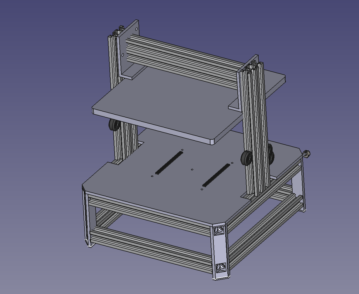
- Design and build of the main frame for the jig
PCB target dimmensions are 230x230mm to be able to run bigger boards or even small panels
As many of the shelf parts should be used, and the jig must be buildable without too much tools or experience
- Design and build of the electronic boards to let the magic happen
Most of the complexity should reside in the mainboard of the system, leaving "per-board" adapters to be as simple and cheap as possible
As many use cases as practically viable should be taken into account- KiCad plugin to automate the generation of the "per-board" adapters as much as possible
- Firmware to run on the onboard microcontroller
- SDK / application examples of the control software side, which operates the jig
--> using https://github.com/snhobbs/kicad-parts-placer and https://github.com/snhobbs/kicad-testpoints-pcm ?As this project is at the very beginning, the only way to get one is to build it yourself using the BOM and Gerbers in the release pages. In the future, I hope to be able to sell kits for the system, as well as the individual parts.
As it might show, I'm not really an expert on the subject (on anything actually), so help is very welcome! If you would like to contribute to the project, Check out the contributing page to get started.
Discussion about the project happens on the Discord server!
| Qty | Value | Footprint | References |
|---|---|---|---|
| 12 | 100n | Capacitor_SMD:C_0402_1005Metric | C19, C22, C23, C24, C25, C26, C27, C28, C29, C30, C31, C34 |
| 12 | 100nF | Capacitor_SMD:C_0402_1005Metric | C10, C13, C14, C15, C16, C46, C47, C48, C49, C50, C51, C52 |
| 10 | 100k | Resistor_SMD:R_0402_1005Metric | R4, R5, R28, R29, R32, R33, R38, R39, R42, R43 |
| 10 | R | Resistor_SMD:R_0402_1005Metric | R46, R47, R48, R49, R50, R51, R52, R53, R54, R55 |
| 8 | 1k | Resistor_SMD:R_0402_1005Metric | R17, R19, R24, R31, R40, R41, R44, R45 |
| 5 | IN-S42BT5G | LED_SMD:LED_0402_1005Metric | D6, D7, D8, D9, D10 |
| 4 | 100nF | Capacitor_SMD:C_0603_1608Metric | C2, C3, C4, C8 |
| 4 | C | Capacitor_SMD:C_0402_1005Metric | C54, C55, C56, C57 |
| 4 | MAX14661ETI+ | MAX14661ETI-:21-0139I_T2844-1_MXM | U14, U15, U16, U17 |
| 4 | MAX14662 | Package_DFN_QFN:QFN-28-1EP_4x4mm_P0.4mm_EP2.6x2.6mm | U7, U8, U12, U13 |
| 4 | MountingHole | MountingHole:MountingHole_3.2mm_M3 | H1, H2, H3, H4 |
| 3 | 10k | Resistor_SMD:R_0402_1005Metric | R3, R7, R8 |
| 3 | 1uF | Capacitor_SMD:C_0603_1608Metric | C1, C7, C9 |
| 3 | 4.7u | Capacitor_SMD:C_0402_1005Metric | C17, C18, C20 |
| 2 | 100R | Resistor_SMD:R_0402_1005Metric | R11, R12 |
| 2 | 15p | Capacitor_SMD:C_0402_1005Metric | C32, C33 |
| 2 | 2,2k 1% | Resistor_SMD:R_0603_1608Metric | R36, R37 |
| 2 | 20pF | Capacitor_SMD:C_0402_1005Metric | C11, C12 |
| 2 | 220R | Resistor_SMD:R_0402_1005Metric | R15, R16 |
| 2 | 22R | Resistor_SMD:R_0402_1005Metric | R1, R2 |
| 2 | 27 | Resistor_SMD:R_0402_1005Metric | R20, R21 |
| 2 | 30pF | Capacitor_SMD:C_0402_1005Metric | C43, C44 |
| 2 | 4.7uF | Capacitor_SMD:C_0402_1005Metric | C21, C53 |
| 2 | 4k7 | Resistor_SMD:R_0402_1005Metric | R13, R14 |
| 2 | 5,1k | Resistor_SMD:R_0402_1005Metric | R27, R35 |
| 2 | C | Capacitor_SMD:C_0603_1608Metric | C5, C6 |
| 2 | Fuse | Fuse:Fuse_0603_1608Metric | F1, F2 |
| 2 | INA138 | Package_TO_SOT_SMD:SOT-23-5 | U5, U11 |
| 2 | LT1910ES8#PBF | LT1910ES8#PBF:SOIC127P599X175-8N | IC1, IC2 |
| 2 | SW_Push | Button_Switch_SMD:SW_Push_1P1T_NO_Vertical_Wuerth_434133025816 | SW1, SW2 |
| 1 | 0 | Resistor_SMD:R_0402_1005Metric | R22 |
| 1 | 12k 1% | Resistor_SMD:R_0402_1005Metric | R34 |
| 1 | 1K5 | Resistor_SMD:R_0402_1005Metric | R6 |
| 1 | 3.3u | Inductor_SMD:L_2010_5025Metric | L1 |
| 1 | 33 | Resistor_SMD:R_0402_1005Metric | R18 |
| 1 | 39k | Resistor_SMD:R_0402_1005Metric | R9 |
| 1 | ABM8-272-T3 | Crystal:Crystal_SMD_3225-4Pin_3.2x2.5mm | Y3 |
| 1 | ATmega32U4-M | Package_DFN_QFN:QFN-44-1EP_7x7mm_P0.5mm_EP5.2x5.2mm | U1 |
| 1 | B5819W | Diode_SMD:D_SOD-123 | D1 |
| 1 | BLUE | LED_SMD:LED_0603_1608Metric | D2 |
| 1 | DNF | Resistor_SMD:R_0402_1005Metric | R23 |
| 1 | DNP | Resistor_SMD:R_0402_1005Metric | R10 |
| 1 | ECS-240-20-33-TR3 | Crystal:Crystal_SMD_EuroQuartz_MT-4Pin_3.2x2.5mm | Y4 |
| 1 | External Supply | TerminalBlock_Phoenix:TerminalBlock_Phoenix_MKDS-1,5-2-5.08_1x02_P5.08mm_Horizontal | J5 |
| 1 | FSUSB42MUX | Package_SO:MSOP-10_3x3mm_P0.5mm | U10 |
| 1 | GPIOS | Connector_PinSocket_2.54mm:PinSocket_2x30_P2.54mm_Vertical_SMD | J2 |
| 1 | MH2029-300Y | Inductor_SMD:L_0805_2012Metric | FB1 |
| 1 | Main Power | TerminalBlock_Phoenix:TerminalBlock_Phoenix_MKDS-1,5-2-5.08_1x02_P5.08mm_Horizontal | J4 |
| 1 | Power | Connector_PinSocket_2.54mm:PinSocket_2x30_P2.54mm_Vertical_SMD | J1 |
| 1 | RED | LED_SMD:LED_0603_1608Metric | D3 |
| 1 | RP2350_80QFN | RP2350B:RP2350-QFN-80-1EP_10x10_P0.4mm_EP3.4x3.4mm_ThermalVias | U3 |
| 1 | S9013 | Package_TO_SOT_SMD:SOT-23 | Q1 |
| 1 | STM32F103CB | Package_QFP:LQFP-48_7x7mm_P0.5mm | U2 |
| 1 | TPS55289 | TPS55289:TPS55289 | U6 |
| 1 | USB2514B-I/M2 | Package_DFN_QFN:QFN-36-1EP_6x6mm_P0.5mm_EP3.7x3.7mm | U9 |
| 1 | USB4105-GF-A | USBC:GCT_USB4105-GF-A | J6 |
| 1 | W25Q128JVS | Package_SO:SOIC-8_5.23x5.23mm_P1.27mm | U4 |
| 1 | ~ | Jumper:SolderJumper-3_P1.3mm_Bridged12_Pad1.0x1.5mm | JP1 |
The 146 most common of 147 parts.
vamatis/UMMTJ
A universal Test jig setup for small production and prototype shops


thecasterian/STM32F401-Playground
Have fun with an STM32F401 breakout board


xwlred/OpenHD-CM4-Carrier-Board
[Shelved] RPI CM4 carrier for use in OpenHD


It measures 100 × 100 mm and has 4 copper layers, 1.6 mm thick.
147 parts, built around the ATMEGA32U4-MU, STM32F103CBT6, MAX14661ETI+ and LT1910ES8#PBF. The full list of its parts is on this page, with links to each part's symbol and footprint where PCBKit's library has them.
From the vamatis/UMMTJ repository on GitHub, at the commit this page was made from: the board is PCB/MainBoard/UMMTJ_Mainboard.kicad_pcb and its schematic PCB/MainBoard/AVR.kicad_sch. PCBKit opens the board in the browser, with nothing to install.
Its repository states no licence, so its author keeps all rights: ask vamatis before reusing the design.