2 layers198.1 × 30.5 mm
Splitflap driver
drandyhaas/KiCadRoutingTools
A set of Python/Rust tools to aid routing in KiCad
65 parts744MIT

 Twistiee/rcm
A CAN-controlled relay driver for a car. 21 universal channels, each of which is simultaneously a low-side output and an input — so the same board builds as a relay controller or as a switch panel, decided in firmware…
Rcm is an open-source printed circuit board by Twistiee, from the Twistiee/rcm repository on GitHub. It is a 4-layer board of 140 × 70 mm with 159 parts on 170 nets, routed with 1,765 tracks and 189 vias.
It is built around the STM32F446RET6, SN65HVD230D and TPL7407LD, with the 74HC165D, 74HC595 and AMS1117-3.3 among its other parts. Its parts include 2 diodes, 2 crystals and 1 fuse. It belongs with the STM32 boards of this library.


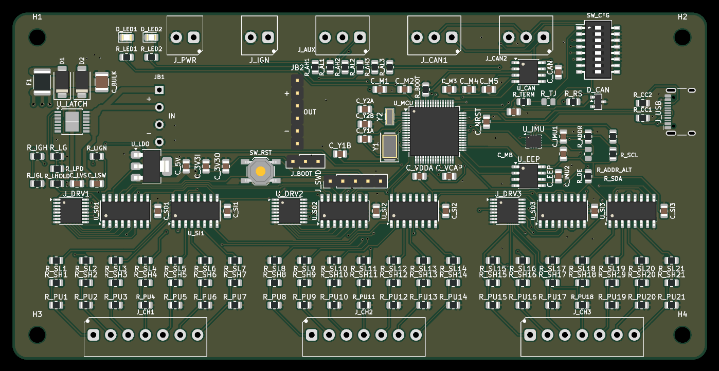
A CAN-controlled relay driver for a car. 21 universal channels, each of which is simultaneously a low-side output and an input — so the same board builds as a relay controller or as a switch panel, decided in firmware rather than by a different PCB.
Designed for a rusEFI bus (uaEFI SUPER ECU + uaDASH display), but nothing about it is rusEFI-specific beyond the choice of message IDs.
A note on how this was built
This project is largely AI-developed. The schematic, PCB layout, firmware and documentation were written by me working with Claude, and much of the text and code here came out of that. It is called out up front because some people would rather know, and because it should colour how much you trust it.
What it does not mean is unreviewed or untested. The board exists and has been brought up on the bench; the claims in the Status section below were measured rather than asserted, and where something has only been reasoned about it says so. The firmware has a host-side unit test suite. Bring-up still found real bugs that review had missed — which is rather the point of the Status section.
Treat it as you would any one-person hobby project: read the schematic before you build it, and don't put it in charge of anything you can't afford to have fail.
revA has been built, powered and brought up. Every subsystem has run on real
hardware: the MCU and its 8 MHz crystal (in use only since 2026-10-26 -- see "The core
runs from the crystal" in firmware/README.md), USB, the DIP straps, the EEPROM, CAN through the
transceiver onto a real bus, the IMU, the 12 V sense, the self-latching power, the
watchdog, the output drivers under a real relay load, a stored configuration surviving a
full save-reset-read cycle, and the board switching itself off. 289 host unit tests pass
alongside that.
What that does not mean is that it is proven in a car. Specifically, still untested:
One genuine hardware flaw has been found, and it is a missing capability rather than a
functional fault: revA cannot reach USB DFU. BOOT1 is PB2, which this board uses
for SR_OE_N and holds high at reset, so lifting BOOT0 boots from SRAM instead of the ROM
bootloader. The J_BOOT header is fitted and works; the pin conflict defeats it. Firmware
therefore needs an ST-Link on J_SWD. Configuration is unaffected — that is all over CAN.
DESIGN.md has the analysis and the one-net revB fix.
Bring-up found three real firmware bugs that no amount of desk testing had: a %f in
printf corrupting memory, a strap display that could never show a change, and a short
press on the ignition button switching the board back off. DESIGN.md records those and
everything else found along the way, which is a fair guide to how much is probably left.
This is a PDM. Running a main relay, a fuel pump and an injector feed is the job, not an edge case. But there is one behaviour to design around:
On any reset, R_OE parks all 21 channels high-impedance until firmware re-enables
them. Every channel drops. The firmware adopts failsafe_state and goes live as its
first act, and on revA hardware that is 22 ms, measured by the self-test build's W
command rather than estimated. Add a few ms of pre-main() crystal and PLL startup that
millis() cannot see, so call it ~25 ms. That applies equally to a cold start and to
a watchdog reset, so a main relay behind this board closes with the key rather than after
a timeout.
Most of the 22 ms is the EEPROM: the board cannot apply failsafe_state before it has
read failsafe_state, so cfg_load() is unavoidably inside the dropout. A scope on any
channel gives the true figure including pre-main() time.
So the question for each load is not "is this engine-critical" but "what does 25 ms off do to it?"
| Load | 25 ms off | Verdict |
|---|---|---|
| Fan, fuel pump, lights, horn, accessories | invisible | fine |
| Injector / coil supply via a main relay | at worst a single missed event | fine — set failsafe_state to hold it on |
| ECU power itself | the ECU reboots, which really is a stall | give the ECU its own ignition-switched feed |
| Brake lights | harmless in itself | hardwire anyway — see below |
failsafe_state is the board's resting state, not just a bus-timeout behaviour: it is
what gets applied at power-up, after a watchdog reset, and whenever the bus goes quiet —
anything a CAN command has not overridden. It defaults to all-off, which is right for
lighting and wrong for anything that should be on by default. It is per-channel, so one
board can drop its lighting and hold its engine loads. Set it deliberately.
Brake lights are a different argument. Not dropout time — a hardwired brake switch is
simply simpler and more reliable than anything running on a microcontroller, and there is
no upside to inserting one. Wire the switch straight through, and tap the switched feed
into a spare channel set to CH_INPUT if you want the board to know about it. 1.2 mA, and
it cannot affect the lamps.
Roadworthiness and legal compliance of anything you build with this are yours.
| Channels | 21, low-side switched, 7 per driver |
| Drivers | 3 × TPL7407L (MOSFET, not Darlington — see below) |
| I/O expansion | 74HC595 out / 74HC165 in, daisy-chained |
| MCU | STM32F446RET6, LQFP-64 |
| Bus | CAN, switchable termination, any exact bitrate |
| Sensing | every channel is read back continuously, including while driving |
| IMU | Bosch BMI270, 6-axis |
| Board | 140 × 70 mm, 4-layer, solid ground plane |
| Supply | 7–30 V (12 V nominal); board draws ~100 mA |
| Per channel, one or two on | 600 mA sink, 30 V max |
| Per channel, all 7 of a tile on | ~250 mA — limited by the driver package, not the silicon |
| All 21 channels | ~3.5 A total with typical 85 Ω relay coils |
| Ground return | all channels share one pole on J_PWR, ~8 A |
| Ambient | −20 to +70 °C |
The channels switch relay coils, they do not carry load current — that is the whole
architecture. DESIGN.md has the worked numbers, including why 600 mA is not an all-on
figure.
Each channel's terminal connects to three things at once — a driver output, a permanently connected 1M/270k sense divider, and a fitted 10k pull-down:
Getting all three from one resistor took a few goes. A pull-up would have been the obvious choice and it silently breaks fuse sensing: blown and healthy both read high, 20mV apart.
The same pull-down has a sting worth knowing: an un-driven channel is not open, it is
10k to ground, and it will pass ~1mA from anything pulled up to 12V. Relay coils ignore
that. Optocouplers and MOSFET gates do not — so a generic "active low" relay module wired
straight to a channel sits with its relays energised. DESIGN.md has the fix.
An 8-way DIP sets what can't be fixed over the bus once it's wrong:
| Pos | Function |
|---|---|
| 1 | CAN termination (passive, parallels a solder jumper) |
| 2 | Role — relay module or keypad |
| 3–4 | Node address |
| 5 | CAN bitrate — forces 500k, for when you configure yourself off the bus |
| 6 | Publish IMU data — only one board per car should |
Four relay modules and four keypads can share a bus. Everything else — channel modes, bitrate, message IDs, failsafe states — lives in EEPROM and is changeable over CAN.
PlatformIO + STM32duino, in firmware/ — see
firmware/README.md for the detail.
pio run -d firmware                     build
pio run -d firmware -e selftest -t upload   bring-up console over USB-C
pio test -d firmware -e native          289 host unit tests
Two bring-up paths. A USB-C console needs nothing but the cable — it proves the
DIP, the EEPROM, the CAN controller via internal loopback, the IMU, and walks all 21
channels. A PC-side CAN tool (firmware/tools/rcm_bench.py, any python-can interface)
does monitoring, commanding and the same channel walk over the bus.
The unit tests compile the firmware's own source against a model of the board — the shift register chains bit by bit, each channel's electrical behaviour, and the EEPROM including its page-wrap misbehaviour. They exist because the shift-register byte order is the one thing in this design that cannot be checked by reading the code back.
Message IDs were checked against rusEFI's own source rather than guessed. The board sits at
base 0x300, clear of everything rusEFI uses (0x100/0x102, 0x130/0x131, 0x190,
0x200–0x20B, OpenBLT, OBD2). The base is configurable if it clashes with something on
your loom.
docs/rcm.dbc is generated from the firmware headers, so uaDASH and
TunerStudio can render channel state, inputs and faults with no custom display code.
The board can drive channels from the ECU's own decisions, and ask the ECU to act. rusEFI broadcasts what it thinks its relays should be doing — main relay, fuel pump, both fans, O2 heater, check-engine, rev limiter — as single bits. Any of those can be bound to a channel, so the ECU decides and this board switches, which matters because rusEFI has far fewer outputs than this board has channels. In the other direction, a button can send any TunerStudio command: start/stop the engine, or one of rusEFI's Lua command counters, which is how you get traction control, launch control or a map switch without either side needing new firmware.
The BMI270 publishes as a Bosch MM5.10 at 0x174/0x178/0x17C — frames rusEFI
already decodes. Set imuType = IMU_MM5_10 and yaw rate plus lateral, longitudinal and
vertical G appear in the ECU with nothing else to configure.
enclosure/ generates a sealed 3D-printable box and two lids — a keypad face
carrying eight 25 mm anti-vandal switches, and a blank plate for the relay-control build.
Wire entry is DEUTSCH DT, one aperture that fits 2, 3 and 4-way alike.
Like the PCB, it is generated by a script rather than modelled by hand; the .FCStd files
are output and are overwritten on every build.
The schematic and PCB are generated, not drawn:
python gen_spec.py     ->  spec.json        the circuit, and the source of truth
python gen_plan.py     ->  board_plan.json  every part's physical position
tools/                                      schematic, placement, routing, export
Editing rcm.kicad_sch or rcm.kicad_pcb by hand gets overwritten. Change the generator.
mfg/ holds the gerbers, BOM and CPL exactly as ordered, so you can send that folder to a
board house without running any of the above. It is set up for JLCPCB assembly: 4-layer,
leaded HASL, Standard PCBA (the BMI270's LGA-14 package requires it).
The board house builds the board. These are not on the BOM and will not arrive with it — either because they do not mount to the PCB, or because no standard part fits.
A Waveshare DC5-36-TO-DC3V3-5 step-down module, socketed onto JB1/JB2. It takes the
ignition-latched 12V rail down to 5V, which the on-board LDO then drops to 3V3.
It ships set to 5V output and must stay that way. Getting 3V3 from the module instead needs per-unit pad rework, and forgetting it once puts 5V into a 3.3V MCU. The LDO exists precisely so that step is never required.
Two things go with it:
JB2 (output, row of 6) | ordinary 2.54mm male header, on the BOM (C37208) |
JB1 (input, 4 pins) | hand-fit — 3.50mm pitch, no header is made at that spacing |
JB1 needs four individual square pins. They set the module's ride height, so fit them
before anything else and get it square.
The board carries the header halves; the screw plugs are yours to buy. KF2EDGK-3.5-xP,
also sold as 15EDGK-3.5:
| Plug | LCSC | Mates with | Per board |
|---|---|---|---|
| 2P | C440847 | J_PWR, J_IGN | 2 |
| 3P | C440848 | J_AUX, J_CAN1, J_CAN2 | 3 |
| 7P | C440852 | J_CH1, J_CH2, J_CH3 | 3 |
About $3.20 a board. Generic parts — any supplier stocks them.
Do not buy these into JLC's Parts Library expecting them to ship with the boards. Confirmed the hard way on the 2026-08-08 order. That library is consignment stock for assembly runs, and JLC will only ship a part if the assembly process solders it down — a loose mating plug does not qualify. They will not add it to the board, and they will not put it in the box for a sane handling fee either. Money spent there is stuck: you own the parts and there is no way to take delivery of them.
Buy the plugs somewhere else entirely.
R_TJ | 0R 0805 (C17477) — solder for permanent CAN termination instead of the DIP |
| Momentary buttons | for a keypad build: 8 off, positive-switched to +12V |
| USB-CAN adapter | for the PC-side tool. Get one with slcan firmware |
gen_spec.py      -> spec.json         circuit definition, the source of truth
gen_plan.py      -> board_plan.json   every part's physical position
jlc_parts.json                        LCSC part per line; stamped into the schematic
tools/                                scripted-board pipeline
mfg/                                  gerbers, BOM, CPL as ordered
firmware/                             STM32 firmware, host unit tests, PC tools
enclosure/                            generated 3D-printable box and lids
docs/rcm.dbc                          CAN database, generated from the firmware headers
SPEC.md / DESIGN.md what was built, and whyDESIGN.md is a decision log rather than a specification, and it keeps the mistakes in.
Some that seem worth repeating here:
Three faults were caught after the board looked finished and every automated check was green — a missing ground pour, a reverse-polarity diode wired backwards, and stale manufacturing files. Two were spotted by eye, not by tooling. ERC passes a diode in either orientation, and DRC says nothing at all about an absent copper pour.
The unit tests earned their keep before any hardware existed. They caught a mirrored shift-register byte order, a CAN filter that made every other filter decorative, four broadcast frames being handed to three transmit mailboxes, and a multi-second output dropout after a watchdog reset. The pattern in every case was two independent derivations of the same fact disagreeing — which is why the tests model the hardware rather than restating the driver.
JB1 (the buck's input pins, 4 holes at 3.50mm pitch) is hand-fit — no header is made
at that pitch. Respacing it to 2.54mm is the obvious fix for a revision.
firmware/lib/bmi270/ is Bosch Sensortec's own
BMI270 Sensor API, vendored verbatim
under BSD-3-Clause. It carries the 8 KB configuration image the sensor needs at every
power-up, which is not something worth reimplementing.
MIT — hardware design files included. Copy it, change it, sell it, no attribution burden beyond keeping the notice.
MIT rather than a public-domain dedication for one reason: the "AS IS, WITHOUT WARRANTY" clause. This switches vehicle electrics, and that paragraph is worth keeping.
Bosch's vendored BMI270 driver is separately licensed under BSD-3-Clause.
| Qty | Value | Footprint | References |
|---|---|---|---|
| 25 | 1M | Resistor_SMD:R_0805_2012Metric | R_AH1, R_AH2, R_AH3, R_IGH, R_SH1, R_SH2, R_SH10, R_SH11, R_SH12, R_SH13, R_SH14, R_SH15, R_SH16, R_SH17, R_SH18, R_SH19 +9 |
| 25 | 270k | Resistor_SMD:R_0805_2012Metric | R_AL1, R_AL2, R_AL3, R_IGL, R_SL1, R_SL2, R_SL10, R_SL11, R_SL12, R_SL13, R_SL14, R_SL15, R_SL16, R_SL17, R_SL18, R_SL19 +9 |
| 24 | 10k | Resistor_SMD:R_0805_2012Metric | R_BOOT, R_OE, R_PU1, R_PU2, R_PU10, R_PU11, R_PU12, R_PU13, R_PU14, R_PU15, R_PU16, R_PU17, R_PU18, R_PU19, R_PU20, R_PU21 +8 |
| 20 | 100nF | Capacitor_SMD:C_0805_2012Metric | C_3V3O, C_CAN, C_EEP, C_IMU1, C_IMU2, C_LSW, C_LVS, C_M1, C_M2, C_M3, C_M4, C_M5, C_NRST, C_SI1, C_SI2, C_SI3 +4 |
| 4 | 20pF | Capacitor_SMD:C_0805_2012Metric | C_Y1A, C_Y1B, C_Y2A, C_Y2B |
| 4 | MountingHole_3.2mm_M3 | MountingHole:MountingHole_3.2mm_M3 | H1, H2, H3, H4 |
| 3 | 0R | Resistor_SMD:R_0805_2012Metric | R_ADDR, R_ADDR_ALT, R_TJ |
| 3 | 1k | Resistor_SMD:R_0805_2012Metric | R_LED1, R_LED2, R_LHOLD |
| 3 | 74HC165 | Package_SO:SOIC-16_3.9x9.9mm_P1.27mm | U_SI1, U_SI2, U_SI3 |
| 3 | 74HC595 | Package_SO:SOIC-16_3.9x9.9mm_P1.27mm | U_SO1, U_SO2, U_SO3 |
| 3 | TPL7407L | Package_SO:TSSOP-16_4.4x5mm_P0.65mm | U_DRV1, U_DRV2, U_DRV3 |
| 2 | 10uF_25V | Capacitor_SMD:C_0805_2012Metric | C_3V3I, C_5V |
| 2 | 4.7k | Resistor_SMD:R_0805_2012Metric | R_SCL, R_SDA |
| 2 | 5.1k | Resistor_SMD:R_0805_2012Metric | R_CC1, R_CC2 |
| 1 | 10uF_50V | Capacitor_SMD:C_1210_3225Metric | C_BULK |
| 1 | 120R | Resistor_SMD:R_0805_2012Metric | R_TERM |
| 1 | 2.2uF | Capacitor_SMD:C_0805_2012Metric | C_VCAP |
| 1 | 22k | Resistor_SMD:R_0805_2012Metric | R_LPD |
| 1 | 32.768kHz | Crystal:Crystal_SMD_3215-2Pin_3.2x1.5mm | Y2 |
| 1 | 4.7uF | Capacitor_SMD:C_0805_2012Metric | C_MB |
| 1 | 47R | Resistor_SMD:R_0805_2012Metric | R_LG |
| 1 | 47k | Resistor_SMD:R_0805_2012Metric | R_LIGN |
| 1 | 8MHz | Crystal:Crystal_SMD_5032-2Pin_5.0x3.2mm | Y1 |
| 1 | AMS1117-3.3 | Package_TO_SOT_SMD:SOT-223-3_TabPin2 | U_LDO |
| 1 | AUX_IN | rcm:TerminalBlock_KF2EDG-3.5-3P_1x03_P3.50mm_Horizontal | J_AUX |
| 1 | BMI270 | Package_LGA:Bosch_LGA-14_3x2.5mm_P0.5mm | U_IMU |
| 1 | BOOT_SEL | Connector_PinHeader_2.54mm:PinHeader_1x03_P2.54mm_Vertical | J_BOOT |
| 1 | BTS7040-1EPZ | Package_SO:Infineon_PG-TSDSO-14-22 | U_LATCH |
| 1 | CAN_A | rcm:TerminalBlock_KF2EDG-3.5-3P_1x03_P3.50mm_Horizontal | J_CAN1 |
| 1 | CAN_B | rcm:TerminalBlock_KF2EDG-3.5-3P_1x03_P3.50mm_Horizontal | J_CAN2 |
| 1 | CFG_DIP | Button_Switch_SMD:SW_DIP_SPSTx08_Slide_KingTek_DSHP08TS_W7.62mm_P1.27mm | SW_CFG |
| 1 | CH1-7 | rcm:TerminalBlock_KF2EDG-3.5-7P_1x07_P3.50mm_Horizontal | J_CH1 |
| 1 | CH15-21 | rcm:TerminalBlock_KF2EDG-3.5-7P_1x07_P3.50mm_Horizontal | J_CH3 |
| 1 | CH8-14 | rcm:TerminalBlock_KF2EDG-3.5-7P_1x07_P3.50mm_Horizontal | J_CH2 |
| 1 | GRN | LED_SMD:LED_0805_2012Metric | D_LED1 |
| 1 | IGN_IN | rcm:TerminalBlock_KF2EDG-3.5-2P_1x02_P3.50mm_Horizontal | J_IGN |
| 1 | M95640 | Package_SO:SOIC-8_3.9x4.9mm_P1.27mm | U_EEP |
| 1 | PPTC_1A | Resistor_SMD:R_1812_4532Metric | F1 |
| 1 | PWR_IN | rcm:TerminalBlock_KF2EDG-3.5-2P_1x02_P3.50mm_Horizontal | J_PWR |
| 1 | RED | LED_SMD:LED_0805_2012Metric | D_LED2 |
| 1 | RESET | Button_Switch_SMD:SW_SPST_TL3342 | SW_RST |
| 1 | SMAJ33A | Diode_SMD:D_SMA | D2 |
| 1 | SN65HVD230 | Package_SO:SOIC-8_3.9x4.9mm_P1.27mm | U_CAN |
| 1 | SS34 | Diode_SMD:D_SMA | D1 |
| 1 | STM32F446RET6 | Package_QFP:LQFP-64_10x10mm_P0.5mm | U_MCU |
| 1 | SWD | Connector_PinHeader_2.54mm:PinHeader_1x05_P2.54mm_Vertical | J_SWD |
| 1 | SZNUP2105L | Package_TO_SOT_SMD:SOT-23 | D_CAN |
| 1 | USB-C | Connector_USB:USB_C_Receptacle_HCTL_HC-TYPE-C-16P-01A | J_USB |
| 1 | WAVESHARE-IN | rcm:WaveshareBuck_IN_2x2_P3.50mm | JB1 |
| 1 | WAVESHARE-OUT | rcm:WaveshareBuck_OUT_3x3_P2.54mm | JB2 |
It measures 140 × 70 mm and has 4 copper layers, 1.6 mm thick.
159 parts, built around the STM32F446RET6, SN65HVD230D, TPL7407LD and 74HC165D. The full list of its parts is on this page, with links to each part's symbol and footprint where PCBKit's library has them.
From the Twistiee/rcm repository on GitHub, at the commit this page was made from: the board is rcm.kicad_pcb and its schematic rcm.kicad_sch. PCBKit opens the board in the browser, with nothing to install.
Its repository states no licence, so its author keeps all rights: ask Twistiee before reusing the design.
drandyhaas/KiCadRoutingTools
A set of Python/Rust tools to aid routing in KiCad

SpaceCadetJ/LoRa-Autonomous-Boat
An embedded-systems project spanning STM32 firmware, LoRa communication, PCB reconstruction and a documented V2 redesign.

sngmn7/STM32_CAN_RTOS_ETHERNET
Rear 존의 말단 두 노드를 한 장의 PCB로 합친 보드. H723 존 컨트롤러는 Nucleo-144 모듈 그대로 두고 J2 로 연결한다.

juleswwebb/portfolio
A static engineering portfolio for https://juleswwebb.github.io/portfolio/.

Ekta-Gupta27/custom-flight-controller-pcb
Custom flight controller PCB designed in KiCad with STM32F7, multiple sensors, CAN, USB, telemetry, PWM and IO interfaces.

kieraneglin/hexagon-art
A passive breakout board: two lever-terminal inputs, three JST XH outputs, all six conductors (RX bus, two spares, +12V, GND, +5V) paralleled straight across. No active components, no regulation, nothing to configure.

Stab-Rabbit-coding/Open-Secure-ESC
Governed by AGENTS.md. Build spec: ../README.md. Plan: Serenity-UAV docs/plans/2026-09-17-001-feat-tilt-controller-open-secure-esc-build-plan.md (U4).
