2 layers102.7 × 40 mm

 Ekta-Gupta27/custom-flight-controller-pcb
Custom flight controller PCB designed in KiCad with STM32F7, multiple sensors, CAN, USB, telemetry, PWM and IO interfaces.
Custom fc rat is an open-source printed circuit board by Ekta-Gupta27, from the Ekta-Gupta27/custom-flight-controller-pcb repository on GitHub. It is a 6-layer board of 51 × 53.5 mm with 122 parts on 158 nets, routed with 2,513 tracks and 312 vias.
It is built around the SN65HVD230D, BMM150 and ICP-20100, with the W25Q128JVSIQ, BMI270 and ICM-42688-P among its other parts. Its parts include 47 capacitors, 31 resistors, 17 connectors, 11 ICs and 9 diodes. It belongs with the sensors and measurement and robots and motor control boards and the STM32 boards of this library.


A custom-designed flight controller PCB developed for embedded flight-control applications, integrating a high-performance STM32 MCU, multiple inertial and pressure sensors, CAN communication, external flash memory, power management, and dedicated FMU/IO interfaces.
The PCB and schematic were designed using KiCad 9.0.7.
This project focuses on the design and development of a custom flight controller PCB with dedicated interfaces for sensors, communication peripherals, power, debugging, telemetry, PWM outputs, and RC input/output.
The design is divided into multiple functional sections:
The primary processing unit is an STM32F765VITx.
The MCU provides the main processing and peripheral interfaces for the flight-control system, including:
A dedicated STM32F103CBTx is used for the IO section of the design.
The IO controller provides interfaces for:
The design incorporates multiple sensors:
6-axis inertial measurement sensor connected through SPI.
6-axis inertial sensor with dedicated interrupt and SPI connections.
Pressure sensor connected through the I2C interface.
Magnetic sensor connected through the I2C interface.
CAN communication is implemented using the SN65HVD230 transceiver with dedicated CANH and CANL connections and protection circuitry.
A USB OTG interface is provided along with USB ESD protection using USBLC6-2P6.
Dedicated connectors are provided for:
Multiple I2C buses are available for sensor and peripheral communication.
Multiple SPI buses are routed to sensors, flash memory, and external interfaces.
The board includes external SPI flash memory:
W25Q128JVS
The flash device is connected to the main MCU through SPI with a dedicated chip-select signal.
The PCB contains dedicated power regulation and filtering circuitry for the different system power domains.
The design includes:
The schematic includes regulators such as:
| Interface | Purpose |
|---|---|
| GPS_PORT | GPS connectivity |
| POWER | Power input |
| TELEM1 | Telemetry |
| TELEM2 | Telemetry |
| TELEM3 | Telemetry |
| CAN_CONN | CAN communication |
| USB_OTG | USB connectivity |
| DEBUG | Debug/programming |
| SPI_PORT | External SPI interface |
| I2C_PORT | External I2C interface |
| UART_I2CB | UART/I2C interface |
| FMU_PWM | PWM outputs |
| IO_PWM | IO PWM interface |
| SBUS_PORT | SBUS interface |
| SBUS_IN | SBUS input |
| PPM_PORT | PPM input |
| IO_DEBUG | IO debugging |
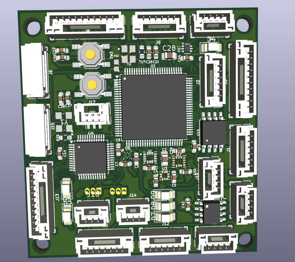
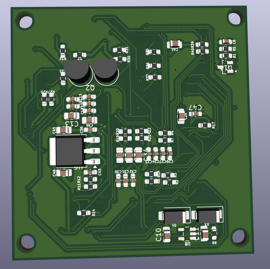
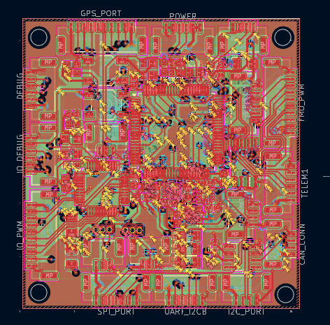
The complete schematic is provided as a multi-page KiCad schematic covering:
The PDF version is available in:
docs/schematic.pdf
The gerbers/ directory contains the manufacturing outputs generated from KiCad, including:
These files can be supplied to a PCB manufacturer for fabrication.
A Bill of Materials generated from the KiCad schematic is included in:
manufacturing/BOM.csv
The BOM contains information such as:
Custom-FC-RAT/
│
├── README.md
├── custom_fc_rat.kicad_pro
│
├── schematic/
│   └── custom_fc_rat.kicad_sch
│
├── pcb/
│   └── custom_fc_rat.kicad_pcb
│
├── gerbers/
│   ├── *.gbl
│   ├── *.gtl
│   ├── *.gbs
│   ├── *.gts
│   ├── *.gbo
│   ├── *.gto
│   ├── *.gm1
│   ├── *.g1
│   ├── *.g2
│   ├── *.g3
│   ├── *.g4
│ ├── *.drl| Tool | Purpose |
|---|---|
| KiCad 9.0.7 | Schematic & PCB design |
| KiCad 3D Viewer | PCB visualization |
| KiCad Gerber Generator | Manufacturing file generation |
Possible future development includes:
The editable KiCad design files and schematic PDF are included so that the hardware design can be inspected and further developed.
Ekta Gupta
Custom PCB / Flight Controller Design Project
Hardware Design Completed
Schematic, PCB layout, 3D visualization, BOM, and manufacturing files are included in this repository.
| Qty | Value | Footprint | References |
|---|---|---|---|
| 27 | 0.1u | Capacitor_SMD:C_0603_1608Metric_Pad1.08x0.95mm_HandSolder | C1, C12, C14, C15, C16, C17, C18, C19, C20, C23, C24, C27, C29, C30, C31, C32 +11 |
| 8 | 4K7 | Resistor_SMD:R_0603_1608Metric_Pad0.98x0.95mm_HandSolder | R2, R3, R4, R7, R8, R16, R39, R40 |
| 6 | LED | LED_SMD:LED_1206_3216Metric_Pad1.42x1.75mm_HandSolder | D2, D4, D5, D7, D8, D9 |
| 5 | 10K | Resistor_SMD:R_0603_1608Metric_Pad0.98x0.95mm_HandSolder | R11, R14, R17, R25, R27 |
| 5 | 220R | Resistor_SMD:R_0603_1608Metric_Pad0.98x0.95mm_HandSolder | R32, R33, R35, R36, R37 |
| 4 | 10u | Capacitor_SMD:C_0805_2012Metric_Pad1.18x1.45mm_HandSolder | C22, C35, C45, C46 |
| 4 | 1u | Capacitor_SMD:C_0805_2012Metric_Pad1.18x1.45mm_HandSolder | C13, C33, C34, C41 |
| 4 | 5K1 | Resistor_SMD:R_0603_1608Metric_Pad0.98x0.95mm_HandSolder | R19, R20, R21, R22 |
| 3 | 2.2u | Capacitor_SMD:C_0805_2012Metric_Pad1.18x1.45mm_HandSolder | C2, C10, C11 |
| 2 | 10k | Resistor_SMD:R_0603_1608Metric_Pad0.98x0.95mm_HandSolder | R9, R30 |
| 2 | 18pF | Capacitor_SMD:C_0603_1608Metric_Pad1.08x0.95mm_HandSolder | C37, C38 |
| 2 | 2u2 | Capacitor_SMD:C_0805_2012Metric_Pad1.18x1.45mm_HandSolder | C25, C28 |
| 2 | 60R | Resistor_SMD:R_0603_1608Metric_Pad0.98x0.95mm_HandSolder | R1, R5 |
| 2 | 8pF | Capacitor_SMD:C_0603_1608Metric_Pad1.08x0.95mm_HandSolder | C21, C26 |
| 2 | BC547 | Package_TO_SOT_THT:TO-92_Inline | Q1, Q2 |
| 2 | SS34 | Diode_SMD:D_SMA | D1, D3 |
| 2 | SW_Push | Button_Switch_SMD:SW_SPST_TL3342 | SW3, SW4 |
| 1 | 10n | Capacitor_SMD:C_0603_1608Metric_Pad1.08x0.95mm_HandSolder | C3 |
| 1 | 150R | Resistor_SMD:R_0603_1608Metric_Pad0.98x0.95mm_HandSolder | R29 |
| 1 | 1k5 | Resistor_SMD:R_0603_1608Metric_Pad0.98x0.95mm_HandSolder | R6 |
| 1 | 1u | Capacitor_SMD:C_0603_1608Metric_Pad1.08x0.95mm_HandSolder | C47 |
| 1 | 22R | Resistor_SMD:R_0603_1608Metric_Pad0.98x0.95mm_HandSolder | R12 |
| 1 | 4.7k | Resistor_SMD:R_0603_1608Metric_Pad0.98x0.95mm_HandSolder | R31 |
| 1 | 4.7n | Capacitor_SMD:C_0603_1608Metric_Pad1.08x0.95mm_HandSolder | C8 |
| 1 | 47R | Resistor_SMD:R_0603_1608Metric_Pad0.98x0.95mm_HandSolder | R15 |
| 1 | BMI270 | My_Footprints:XDCR_BMI270 | U7 |
| 1 | BMM150 | Package_CSP:WLCSP-12_1.56x1.56mm_P0.4mm | U5 |
| 1 | CAN_CONN | Connector_JST:JST_GH_BM04B-GHS-TBT_1x04-1MP_P1.25mm_Vertical | J7 |
| 1 | Crystal_GND24 | My_Footprints:OSC_X322516MLB4SI | Y2 |
| 1 | Crystal_GND24 | My_Footprints:YSX321SL_YXC | Y1 |
| 1 | DEBUG | Connector_JST:JST_GH_SM06B-GHS-TB_1x06-1MP_P1.25mm_Horizontal | J6 |
| 1 | ESD2CANFD24DBZRQ1 | My_Footprints:SOT95P237X112-3N | D11 |
| 1 | FMU_PWM | Connector_JST:JST_GH_BM10B-GHS-TBT_1x10-1MP_P1.25mm_Vertical | J5 |
| 1 | FerriteBead | My_Footprints:BEADC1608X95N | FB2 |
| 1 | GPS_PORT | Connector_JST:JST_GH_BM10B-GHS-TBT_1x10-1MP_P1.25mm_Vertical | J8 |
| 1 | I2C_PORT | Connector_JST:JST_GH_BM04B-GHS-TBT_1x04-1MP_P1.25mm_Vertical | J11 |
| 1 | ICM-42688-P | My_Footprints:PQFN50P300X250X97-14N | U1 |
| 1 | ICP-20100 | My_Footprints:PQFN50P200X200X85-10N | U3 |
| 1 | IO_DEBUG | Connector_JST:JST_GH_SM06B-GHS-TB_1x06-1MP_P1.25mm_Horizontal | J15 |
| 1 | IO_PWM | Connector_JST:JST_GH_BM10B-GHS-TBT_1x10-1MP_P1.25mm_Vertical | J13 |
| 1 | LM1117DT-3.3 | Package_TO_SOT_SMD:TO-252-3_TabPin2 | U6 |
| 1 | POWER | Connector_JST:JST_GH_BM06B-GHS-TBT_1x06-1MP_P1.25mm_Vertical | J9 |
| 1 | PPM_PORT | Connector_JST:JST_GH_BM03B-GHS-TBT_1x03-1MP_P1.25mm_Vertical | J17 |
| 1 | SBUS_IN | Connector_JST:JST_GH_BM03B-GHS-TBT_1x03-1MP_P1.25mm_Vertical | J16 |
| 1 | SBUS_PORT | Connector_JST:JST_GH_BM03B-GHS-TBT_1x03-1MP_P1.25mm_Vertical | J14 |
| 1 | SN65HVD230 | Package_SO:SOIC-8_3.9x4.9mm_P1.27mm | U9 |
| 1 | SPI_PORT | Connector_JST:JST_GH_BM07B-GHS-TBT_1x07-1MP_P1.25mm_Vertical | J3 |
| 1 | STM32F103CBTx | Package_QFP:LQFP-48_7x7mm_P0.5mm | U4 |
| 1 | STM32F765VITx | Package_QFP:LQFP-100_14x14mm_P0.5mm | U2 |
| 1 | TELEM1 | Connector_JST:JST_GH_BM06B-GHS-TBT_1x06-1MP_P1.25mm_Vertical | J1 |
| 1 | TELEM2 | Connector_JST:JST_GH_BM06B-GHS-TBT_1x06-1MP_P1.25mm_Vertical | J2 |
| 1 | TELEM3 | Connector_JST:JST_GH_BM04B-GHS-TBT_1x04-1MP_P1.25mm_Vertical | J10 |
| 1 | TLV75733PDBVR | My_Footprints:SOT95P280X145-5N | U8 |
| 1 | UART_I2CB | Connector_JST:JST_GH_BM06B-GHS-TBT_1x06-1MP_P1.25mm_Vertical | J12 |
| 1 | USBLC6-2P6 | Package_TO_SOT_SMD:SOT-666 | U11 |
| 1 | USB_OTG | Connector_JST:JST_GH_BM04B-GHS-TBT_1x04-1MP_P1.25mm_Vertical | J4 |
| 1 | W25Q128JVS | Package_SO:SOIC-8_5.3x5.3mm_P1.27mm | U10 |


FinnKrieger/dashbox-pcb
A two-layer dashboard controller board for the USC Formula Electric car. It sits on the vehicle CAN bus, drives the driver-facing dash, and takes its power from the car's 12 V rail.


desanv01/Flight-Controller-V2
STM32H743 controller: regulated power, signal-only ESC, neutral ArduPilot firmware, manufacturing data and engineering history.

It measures 51 × 53.5 mm and has 6 copper layers, 1.6 mm thick.
122 parts, built around the SN65HVD230D, BMM150, ICP-20100 and W25Q128JVSIQ. The full list of its parts is on this page, with links to each part's symbol and footprint where PCBKit's library has them.
From the Ekta-Gupta27/custom-flight-controller-pcb repository on GitHub, at the commit this page was made from: the board is pcb/custom_fc_rat.kicad_pcb and its schematic schematic/custom_fc_rat.kicad_sch. PCBKit opens the board in the browser, with nothing to install.
Its repository states no licence, so its author keeps all rights: ask Ekta-Gupta27 before reusing the design.