2 layers100 × 64 mm
Rf power monitor rev2
TheKingOfChaos/RF-Power-Monitor
A 2-layer carrier board for the WIZnet W5500-EVB-Pico-PoE. It is 80 x 51.5 mm: exactly as long as the module, so both short edges line up with the module.
129 parts

 TKAman23/AERoS
An All-Encompassing Rocket System (AERoS) currently in development
AERoS is an open-source printed circuit board by TKAman23, from the TKAman23/AERoS repository on GitHub, published under the AGPL-3.0 licence. It is a 4-layer board of 49.5 × 49 mm with 119 parts on 114 nets, routed with 1,103 tracks and 138 vias.
It is built around the STM32F411RET6, BMP390L and SHTC3, with the TPS611781RNWR, TPS62840DLCR and BMI270 among its other parts. Its parts include 37 resistors, 36 capacitors, 11 connectors, 9 ICs and 7 transistors. It belongs with the STM32 boards of this library.


 [blocked]
A high-performance, compact rocket flight controller board designed around the STM32F411RET6 microcontroller. This board integrates power management, sensor telemetry, state logging, and servo control into a single-cell Li-Po powered solution optimized for model rocketry and high-altitude aerospace tracking.
This board is currently in the active development phase. It has been fully routed and designed, but it has NOT been physically manufactured or bench-tested yet.
(No 3D-models for L1, L2, and L3 were available)
| Front 3D Render | Back 3D Render |
|---|---|
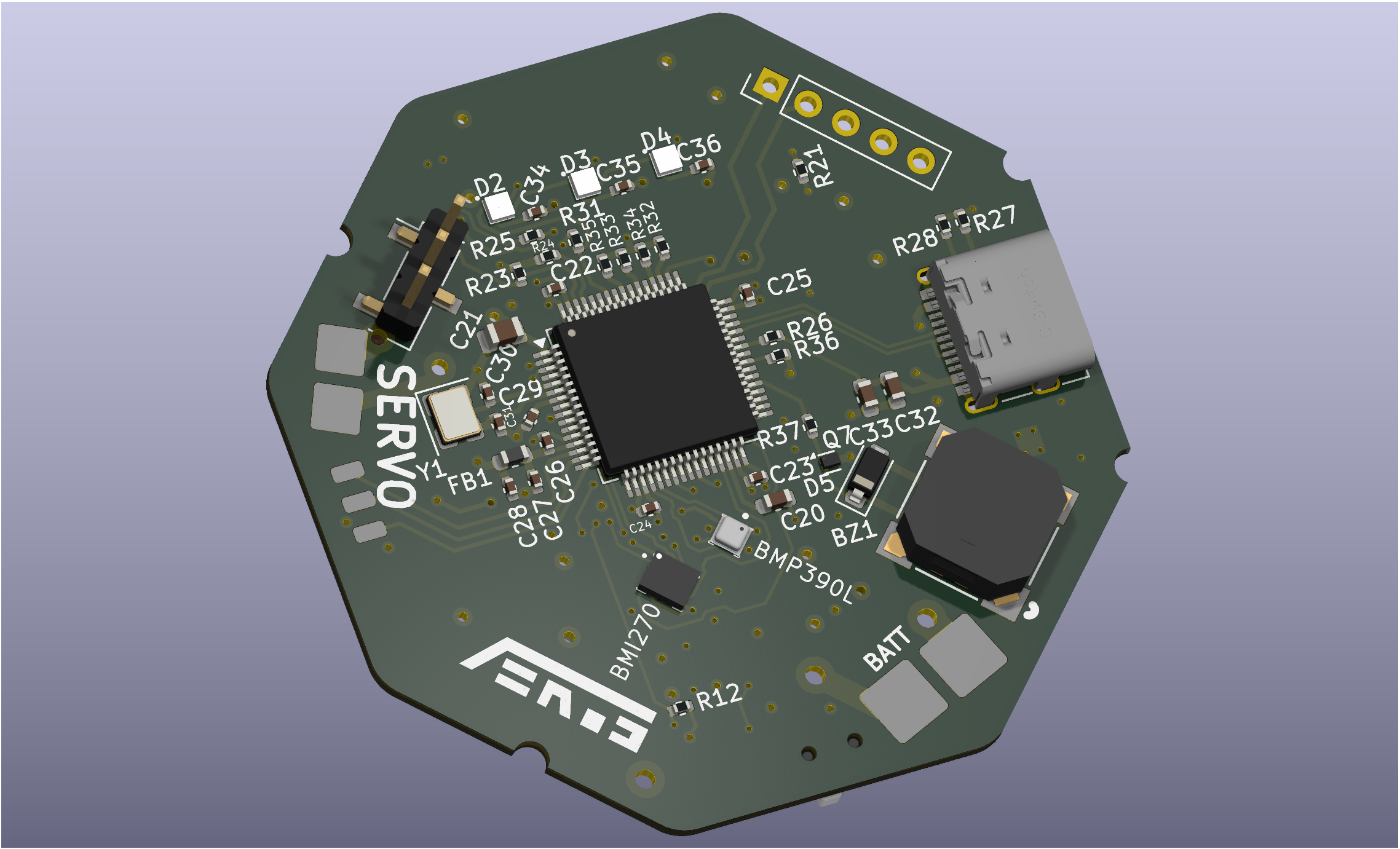 | 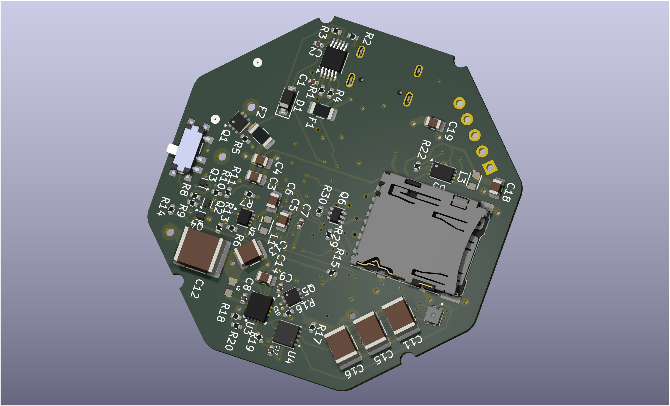 |
   +-----------------------------------------------------------------+
   |                        USB-C 2.0 / Charger                      |
   +-----------------------------------------------------------------+
        |                           |
        v                           v
   +-------+           +-------------------------+           +-------+
   | Battery| ------>  | Self-Latching MOSFET SW |  -------> | Regs  |
   +-------+           +-------------------------+           +-------+
                                                                 |
            +-----------------------+------------+---------------|
            |                                    |               v
            v                                    v       +---------------+
   +-----------------+                  +------------+   | Servo Boost   |
   | STM32F411RET6   | <--- SPI/I2C --- | Sensor Bus |   +---------------+
   | Microcontroller |                  +------------+           |
   +-----------------+------+                                    v
    |      |        |       | ---------------------------> [ Servo Pins ]
    v      v        v       v
  [LEDs][Buzzer][SD Card][ST-Link]
For schematics, open the project file through KiCad 9.0 (can be found in the board directory)
The sensor suite communicates over optimized I2C/SPI buses to provide highly accurate 9-DOF inertial, environmental, and barometric data.
| Sensor Part Number | Type | Primary Flight Function |
|---|---|---|
| BMI270 | 6-Axis IMU (Accel/Gyro) | Rocket orientation, acceleration profiling, launch detection, and apogee sensing. |
| BMP390L | High-Precision Barometer | Precise altitude tracking, descent-rate monitoring, and main/drogue parachute deployment triggering. |
| SHTC3 | Humidity & Temp Sensor | Environmental monitoring and internal enclosure/payload bay diagnostics. |
This project is licensed under the GNU GPL v3 License.
Copyright (c) 2026 Karthikeya Turimalla (TKAman23)

This program is free software: you can redistribute it and/or modify
it under the terms of the GNU General Public License as published by
the Free Software Foundation, either version 3 of the License, or
(at your option) any later version.
See the accompanying LICENSE file for full terms and conditions.
If you use parts of this repository, please reference the repository, my username (TKAman23), or me (Karthikeya Turimalla) in your work.
Since this project is in active prototyping, discussions, issues, and pull requests regarding optimization (especially around power management and thermal layout) are generally welcome! Contact: karthikeyaat@gmail.com.
| Qty | Value | Footprint | References |
|---|---|---|---|
| 13 | 1k | Resistor_SMD:R_0402_1005Metric | R1, R5, R8, R9, R23, R24, R29, R30, R32, R33, R34, R35, R36 |
| 8 | 100n | Capacitor_SMD:C_0402_1005Metric | C7, C8, C9, C22, C23, C24, C25, C29 |
| 6 | 100k | Resistor_SMD:R_0402_1005Metric | R6, R11, R12, R13, R15, R26 |
| 4 | 10u | Capacitor_SMD:C_0805_2012Metric | C5, C6, C19, C21 |
| 4 | 1u | Capacitor_SMD:C_0402_1005Metric | C1, C2, C27, C28 |
| 4 | 4u7 | Capacitor_SMD:C_0805_2012Metric | C3, C4, C14, C18 |
| 4 | MountingHole | MountingHole:MountingHole_2.2mm_M2 | H1, H2, H3, H4 |
| 4 | NMOS | CustomLibrary2:DFN-3(0.6x1) | Q2, Q3, Q4, Q7 |
| 3 | 10k | Resistor_SMD:R_0402_1005Metric | R2, R3, R31 |
| 3 | 220n | Capacitor_SMD:C_0402_1005Metric | C34, C35, C36 |
| 3 | 47u | Capacitor_SMD:C_1812_4532Metric | C11, C15, C16 |
| 3 | Conn_01x01_Pin | Connector_Wire:SolderWirePad_1x01_SMD_1x2mm | J5, J6, J7 |
| 3 | SK6805 | CustomLibrary2:SK6805-EC15 | D2, D3, D4 |
| 2 | 2u2 | CustomLibrary2:IND_LQH2MPZ2R2MGRL | L1, L3 |
| 2 | 30p | Capacitor_SMD:C_0402_1005Metric | C30, C31 |
| 2 | 5k1 | Resistor_SMD:R_0402_1005Metric | R27, R28 |
| 2 | Conn_01x01_Pin | CustomLibrary2:Pad_3x3mm | J3, J4 |
| 2 | Conn_01x01_Pin | CustomLibrary2:Pad_4x4mm | J1, J2 |
| 2 | PMOS | CustomLibrary2:DFN-6-2EP_(AGM20P16AS) | Q1, Q5 |
| 2 | SD101CW-E3-18 | Diode_SMD:D_SOD-123 | D1, D5 |
| 1 | 100 | Resistor_SMD:R_0402_1005Metric | R10 |
| 1 | 100u | Capacitor_SMD:C_2220_5750Metric | C12 |
| 1 | 10n | Capacitor_SMD:C_0402_1005Metric | C26 |
| 1 | 10u | Capacitor_SMD:C_0603_1608Metric | C32 |
| 1 | 121k | Resistor_SMD:R_0402_1005Metric | R16 |
| 1 | 16M | Crystal:Crystal_SMD_3225-4Pin_3.2x2.5mm | Y1 |
| 1 | 1k5 | Resistor_SMD:R_0402_1005Metric | R4 |
| 1 | 1n | Capacitor_SMD:C_0402_1005Metric | C17 |
| 1 | 1u | CustomLibrary2:0806 | L2 |
| 1 | 22n | Capacitor_SMD:C_0201_0603Metric | C10 |
| 1 | 22u | Capacitor_SMD:C_1210_3225Metric | C13 |
| 1 | 267k | Resistor_SMD:R_0402_1005Metric | R7 |
| 1 | 2u2 | Capacitor_SMD:C_0603_1608Metric | C20 |
| 1 | 300k | Resistor_SMD:R_0402_1005Metric | R18 |
| 1 | 365k | Resistor_SMD:R_0402_1005Metric | R14 |
| 1 | 44k2 | Resistor_SMD:R_0402_1005Metric | R19 |
| 1 | 470 | Resistor_SMD:R_0402_1005Metric | R37 |
| 1 | 4u7 | Capacitor_SMD:C_0603_1608Metric | C33 |
| 1 | 500m | Fuse:Fuse_1206_3216Metric | F2 |
| 1 | 50k | Resistor_SMD:R_0402_1005Metric | R25 |
| 1 | 536k | Resistor_SMD:R_0402_1005Metric | R17 |
| 1 | 562k | Resistor_SMD:R_0402_1005Metric | R22 |
| 1 | 600m | Fuse:Fuse_1206_3216Metric | F1 |
| 1 | 78k7 | Resistor_SMD:R_0402_1005Metric | R20 |
| 1 | 976k | Resistor_SMD:R_0402_1005Metric | R21 |
| 1 | BMI270 | Custom_Library:XDCR_BMI270 | U7 |
| 1 | BMP390L | Custom_Library:XDCR_BMP390L | U8 |
| 1 | BQ24090DGQ | Package_SO:HVSSOP-10-1EP_3x3mm_P0.5mm_EP1.57x1.88mm_ThermalVias | U1 |
| 1 | Conn_01x03_Pin | Connector_PinHeader_2.54mm:PinHeader_1x03_P2.54mm_Vertical_SMD_Pin1Left | J8 |
| 1 | Conn_01x05_Pin | Connector_PinHeader_2.54mm:PinHeader_1x05_P2.54mm_Vertical | J10 |
| 1 | GZ1608D121TF | Inductor_SMD:L_0603_1608Metric | FB1 |
| 1 | LOGO | Logos:AERoS-Logo | G*** |
| 1 | MCP1640x-xMC | Package_DFN_QFN:DFN-8-1EP_3x2mm_P0.5mm_EP1.75x1.45mm | U5 |
| 1 | MCP4552T-104E/MF | CustomLibrary2:DFN8_3x3MC_MCH | U4 |
| 1 | MLT-8530 | CustomLibrary2:MLT-8530_JHE | BZ1 |
| 1 | NMOS | Package_TO_SOT_SMD:SOT-363_SC-70-6 | Q6 |
| 1 | SD Card Hirose DM3AT | Connector_Card:microSD_HC_Hirose_DM3AT-SF-PEJM5 | J11 |
| 1 | SHTC3 | Custom_Library:SON100P200X200X80-5N | U9 |
| 1 | STM32F411RET6 | Package_QFP:LQFP-64_10x10mm_P0.5mm | U6 |
| 1 | SW_SPDT | CustomLibrary2:MK-12C02-G020_GSW | SW1 |
| 1 | TPS611781RNWR | Custom_Library:RNW0013A | U3 |
| 1 | TPS62840DLCR | CustomLibrary2:SON50P200X150X100-8N | U2 |
| 1 | USB_C_Receptacle_USB2.0_14P | Connector_USB:USB_C_Receptacle_G-Switch_GT-USB-7010ASV | J9 |
It measures 49.5 × 49 mm and has 4 copper layers, 1.01 mm thick.
119 parts, built around the STM32F411RET6, BMP390L, SHTC3 and TPS611781RNWR. The full list of its parts is on this page, with links to each part's symbol and footprint where PCBKit's library has them.
From the TKAman23/AERoS repository on GitHub, at the commit this page was made from: the board is board/AERoS.kicad_pcb and its schematic board/5v.kicad_sch. PCBKit opens the board in the browser, with nothing to install.
Its repository publishes it under the AGPL-3.0 licence: you may reuse it on that licence's terms (keep the author's notice, and for a copyleft licence share your changes alike).
TheKingOfChaos/RF-Power-Monitor
A 2-layer carrier board for the WIZnet W5500-EVB-Pico-PoE. It is 80 x 51.5 mm: exactly as long as the module, so both short edges line up with the module.

dmcke5/MiniPC_BMS
An all in one power managment solution for powering mini pc's with batteries!

Team-Micras/MicrasPCB
Micras micromouse PCBs as code: Zener circuits, KiCad layouts, CI checks and a design portal


nimishcoder1232/Bedroom-Engineering-Propulsive-Landing-Project
This repo has everything that I made for my rocket that can propulsive landing, while still being under ITAR restrictions.

nimishcoder1232/TVC-Rocket
This is the repo for my TVC rocket that took two years to develop.

Riskerx/QUADCOPTER
QuadCopter Rev B: STM32F401 four-layer flight-controller PCB, manufacturing files, hardware documentation and firmware integration plan.
