


4 layers31.8 × 130 mm

 Riskerx/QUADCOPTER
QuadCopter Rev B: STM32F401 four-layer flight-controller PCB, manufacturing files, hardware documentation and firmware integration plan.
QUADCOPTER is an open-source printed circuit board by Riskerx, from the Riskerx/QUADCOPTER repository on GitHub. It is a 4-layer board of 55.9 × 55.9 mm with 103 parts on 76 nets, routed with 735 tracks and 144 vias.
It is built around the STM32F401CCU6, BMM350 and BMP390L, with the 24LC256-I/P, BH18PB1WHFV-TR and BMI270 among its other parts. Its parts include 30 capacitors, 25 resistors, 7 ICs, 4 diodes and 3 switches. It belongs with the robots and motor control boards and the STM32 boards of this library.


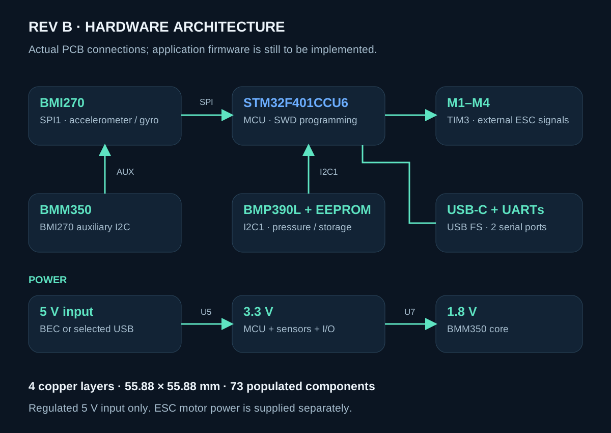
STM32F401CCU6 processing, BMI270 inertial sensing, BMP390L pressure sensing and a BMM350 magnetometer — with four ESC signal outputs, two UARTs, USB-C and SWD in a 55.88 mm square board.
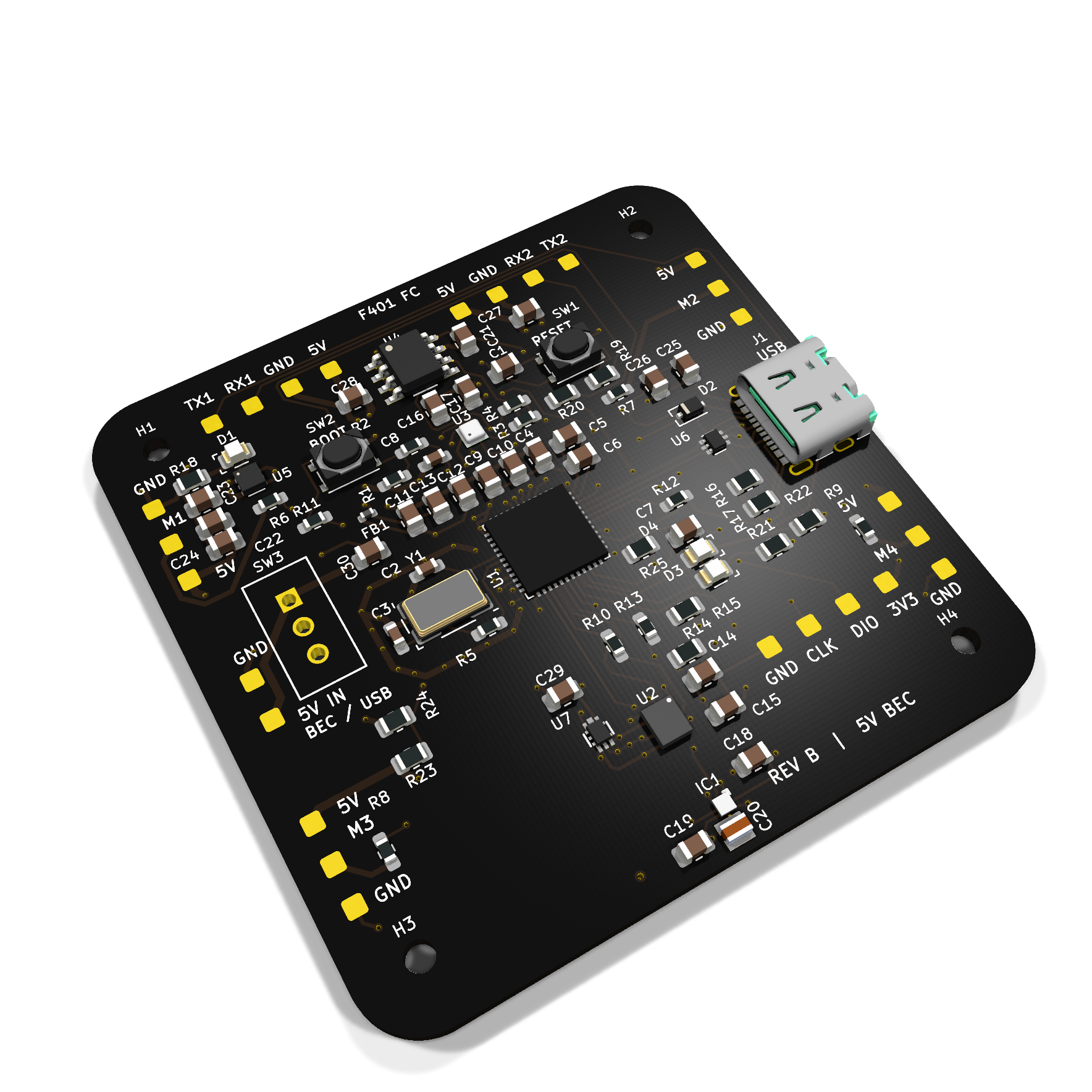
Current milestone: prototype hardware CAD release. The board is fully routed and its configured DRC/ERC checks pass. Firmware integration, first-board bring-up and flight testing remain to be completed. The image is a CAD render; SW3 is not modeled.
Hardware guide · Connections · Firmware integration · Engineering changes · Fabrication instructions
The PCB brings the sensing, processing and low-voltage interfaces of a small quadcopter flight controller onto one board. It is intended to read motion and environmental sensors, communicate with external receiver/telemetry peripherals, and send commands to four separate ESCs once the required firmware is implemented.
This is a flight-controller board, not a motor power-distribution board or an ESC. It contains no radio receiver or GPS module. Its 5 V input requires a regulated BEC; it must not be connected directly to a flight battery.
| Area | State |
|---|---|
| Schematic and four-layer layout | Completed for Rev B |
| Configured DRC errors / warnings | 0 |
| Unrouted connections | 0 |
| Schematic/PCB parity issues | 0 |
| ERC violations | 0 |
| Additional connectivity/value checks | 36 passed |
| Manufacturing and assembly exports | Gerbers, drills, BOM, placement and drawings included |
| Firmware source / binary | Not implemented in this repository |
| Assembly, powered tests, calibration and flight | Pending |
The DRC report, ERC report and validation summary with source hashes provide the evidence. No individual DRC exclusions were added. Inherited ignored rule categories and the J1 local fabrication rule are documented in the engineering notes. These are CAD results, not measured hardware or flight results.
| Feature | Implementation |
|---|---|
| Processor | STM32F401CCU6, Arm Cortex-M4F, up to 84 MHz; 256 KiB flash / 64 KiB SRAM |
| Main clock | 8 MHz ECS crystal; initial 30 pF C0G loads, 0 Ω series jumper |
| IMU | Bosch BMI270, accelerometer + gyroscope, SPI1 |
| Barometer | Bosch BMP390L, I2C1 |
| Magnetometer | Bosch BMM350, auxiliary I2C through BMI270 |
| Storage | 24LC256, 32 KiB I2C EEPROM |
| External control | Four TIM3 ESC signal outputs through 22 Ω series resistors |
| Communications | Two UARTs; USB full-speed device interface via USB-C |
| Debug / boot | SWD pads, RESET and BOOT switches, defined BOOT1 pull-down |
| Power | Regulated 5 V BEC or selected USB; onboard 3.3 V and 1.8 V LDOs |
| Monitoring | Selected 5 V rail sensing on PA0; power, status and error LEDs |
| PCB | 4 layers; 55.88 × 55.88 mm; nominal 1.6 mm thick |
| Mounting | Four Ø2.2 mm M2 clearance holes on a 50.8 mm square pitch |
| Assembly | 73 populated components; top-side placement |
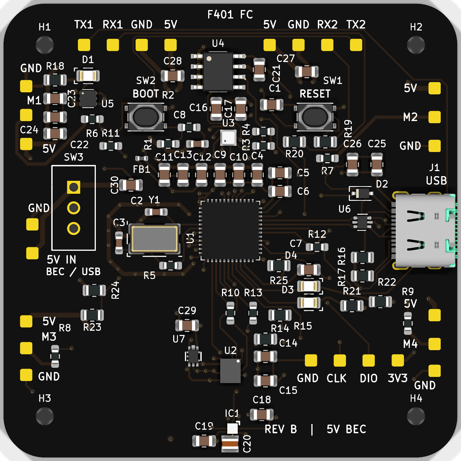
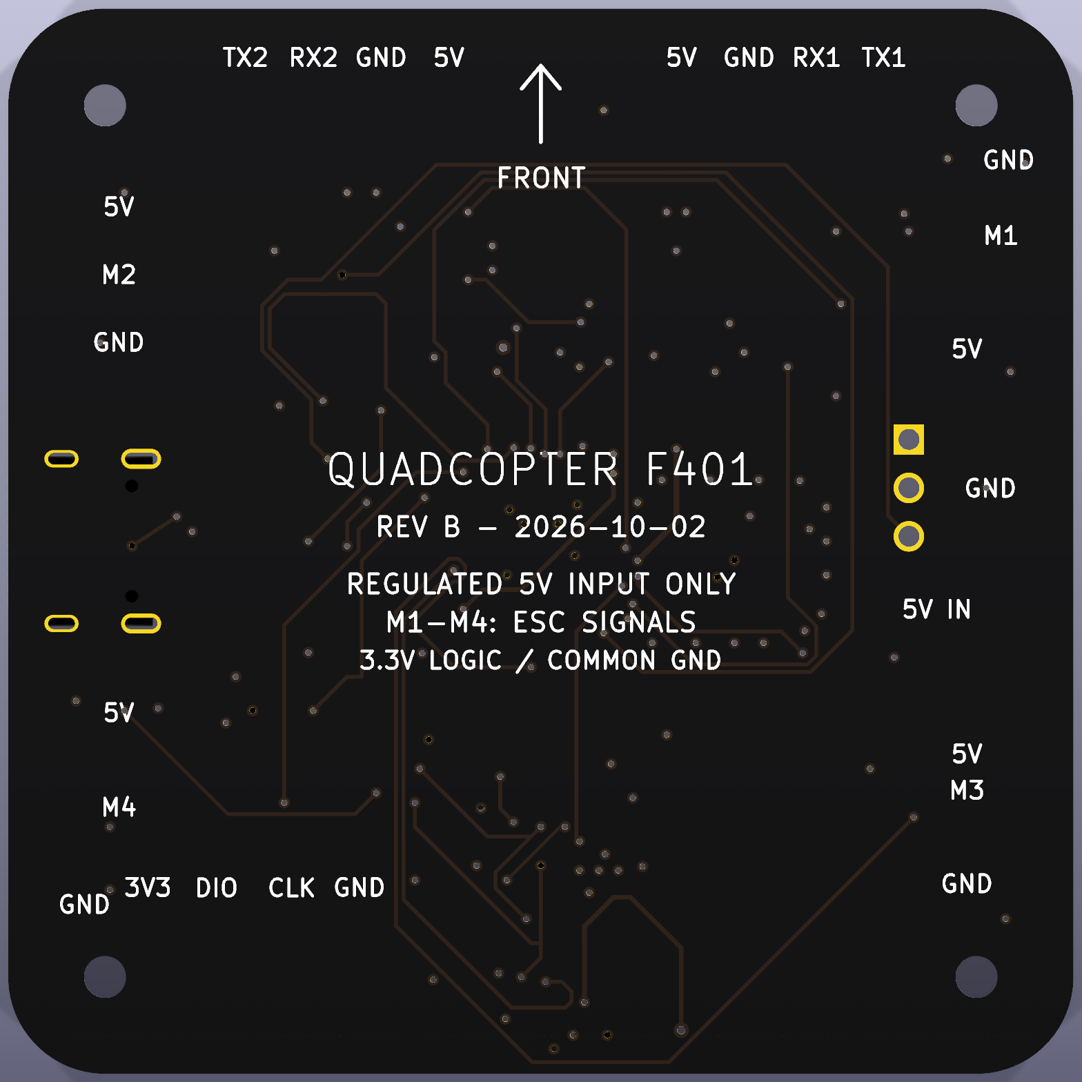
| Top: components and interfaces | Bottom: labels and orientation |
|---|---|
 |  |
Assembly drawing · Top routing view · Bottom routing view · Schematics
The renders use actual project geometry. Custom model alignment is illustrative rather than a certified mechanical enclosure model; standard KiCad 10 3D libraries are needed for a complete local preview.
Regulated 5 V only. SW3 selects the BEC input or diode-isolated USB power. U5 supplies the 3.3 V rail, while U7 supplies the BMM350's 1.8 V core. BMM350 VDDIO and auxiliary-bus pull-ups stay at 3.3 V to match the BMI270. PA0 monitors the selected 5 V rail through a 10 kΩ / 10 kΩ divider.
USB-C uses separate 5.1 kΩ CC pull-downs, both data-contact orientations, grounded shield pads and USBLC6-2P6 protection. SWD remains the primary programming/recovery interface. PA9 is allocated to UART TX, so application firmware must account for unavailable USB VBUS sensing on that pin.
The inner ground plane provides a return path; In2.Cu distributes power. The BMM350 has local core/I/O decoupling and its specified 2.2 µF nonmagnetic CRST capacitor. The MCU analog rail is filtered with a ferrite bead. C2/C3 and R5 still need oscillator startup/drive-level qualification on real hardware.
See hardware details for the power path, PCB stack, sensors, protection and fabrication constraints.
| Label | MCU function | Use |
|---|---|---|
| M1 | PB4 / TIM3_CH1 | ESC1 logic signal |
| M2 | PB5 / TIM3_CH2 | ESC2 logic signal |
| M3 | PB0 / TIM3_CH3 | ESC3 logic signal |
| M4 | PB1 / TIM3_CH4 | ESC4 logic signal |
| TX1 / RX1 | PA9 / PA10 | USART1 |
| TX2 / RX2 | PA2 / PA3 | USART2 |
| CLK / DIO | PA14 / PA13 | SWD clock / data |
| 3V3 | Target reference | SWD target-voltage reference |
| 5V IN / GND | Regulated input | One BEC; no raw LiPo |
| 5V / GND | Selected rail | External low-voltage peripherals |
TX/RX labels are from the controller's perspective. Use compatible 3.3 V logic and a common ground. Motor power goes directly to external ESCs; do not connect motor windings or battery power to the signal pads. Full pad ordering and wiring notes.
This repository currently contains hardware and firmware integration documentation, not flight firmware. There is no flashable binary, tested CubeMX project, ready-made Betaflight/INAV/ArduPilot target or qualified DShot DMA map.
The firmware guide covers:
The intended flow is timestamped sensor acquisition → calibration/filtering → state estimation → control → mixer/limits → ESC commands, supervised by arming and fault logic. Actual scheduling rates, filter settings, PID gains and motor protocol must be selected and validated on the assembled system.
Upstream starting points are STM32CubeF4, BMI270 SensorAPI, BMP3 SensorAPI and BMM350 SensorAPI. They are referenced rather than included as tested dependencies.
QuadCopter.kicad_pro in KiCad 10.99 or a compatible newer version. Close/reload any editor still holding an earlier board before saving.Complete project archive · Archive checksums
Generic passives are specified by value/package/tolerance/dielectric/voltage in the BOM. Use the exact C20 reverse-geometry nonmagnetic part. Confirm the retained ROHM 1.8 V regulator's availability before assembly. Do not infer a high-current peripheral rating or flight certification from the existence of manufacturing files.
Python 3 and the KiCad CLI are required; the CAD verification/export scripts use only Python's standard library.
python3 tools/verify_project.py
python3 tools/build_release.py
Set KICAD_CLI if the executable is not on PATH or at the normal macOS location. Verification refills and saves copper zones, checks schematic parity and ERC, then asserts critical net connections/values. The release builder exports manufacturing data and packages the project. Social image generation is separate; see the image-set instructions.
QuadCopter.kicad_pro / .kicad_pcb / .kicad_dru
QuadCopter.kicad_sch             Root schematic
mcu.kicad_sch                    MCU, clock, reset, debug
IMU.kicad_sch                    Sensor subsystem
power.kicad_sch                  Input selection and rails
pad.kicad_sch                    External pads
libraries/                      Local symbols, footprints, custom models
docs/                           Hardware/connection guides and images
firmware/README.md               Firmware integration plan (no binary)
manufacturing/                  Gerbers, drills, BOM, placement, SVGs
verification/baseline/           Original CAD-check evidence
verification/final/              Rev B reports, views and source hashes
release/                        Fabrication and complete-project archives
social/linkedin/                Caption, four shareable images, alt text
tools/                          Verification, export and media-generation scripts
HARDWARE_RELEASE.md Detailed corrections and bench acceptanceThe revision corrects the 3.3 V supply/LED path, USB-C CC resistor values and connectivity, the ADC divider, magnetometer supply/bypass/CRST connections, boot pull-down and crystal selection. It also completes routing, revises ground returns, refines fine-pitch mask geometry, packages local libraries and reorganizes silkscreen. Before/after details and primary sources.
Download the LinkedIn image kit · Caption · Four-image preview · Upload order and alt text
The images use actual KiCad renders and distinguish CAD verification from pending hardware/firmware tests. Repository access depends on the current GitHub visibility setting.
Hardware CAD is the current milestone. Every future test result should identify the exact PCB revision and firmware commit used.
| Qty | Value | Footprint | References |
|---|---|---|---|
| 1 | 0 | QuadCopter:QC_R5 | R5 |
| 1 | 0.47u | QuadCopter:QC_C29 | C29 |
| 1 | 1.5k | QuadCopter:QC_R3 | R3 |
| 1 | 1.5k | QuadCopter:QC_R4 | R4 |
| 1 | 100n | QuadCopter:QC_C6 | C6 |
| 1 | 100n | QuadCopter:QC_C1 | C1 |
| 1 | 100n | QuadCopter:QC_C11 | C11 |
| 1 | 100n | QuadCopter:QC_C14 | C14 |
| 1 | 100n | QuadCopter:QC_C19 | C19 |
| 1 | 100n | QuadCopter:QC_C8 | C8 |
| 1 | 100n | QuadCopter:QC_C15 | C15 |
| 1 | 100n | QuadCopter:QC_C16 | C16 |
| 1 | 100n | QuadCopter:QC_C18 | C18 |
| 1 | 100n | QuadCopter:QC_C21 | C21 |
| 1 | 100n | QuadCopter:QC_C9 | C9 |
| 1 | 100n | QuadCopter:QC_C17 | C17 |
| 1 | 100n | QuadCopter:QC_C5 | C5 |
| 1 | 100n | QuadCopter:QC_C10 | C10 |
| 1 | 10k | QuadCopter:QC_R23 | R23 |
| 1 | 10k | QuadCopter:QC_R25 | R25 |
| 1 | 10k | QuadCopter:QC_R24 | R24 |
| 1 | 10k | QuadCopter:QC_R1 | R1 |
| 1 | 10u | QuadCopter:QC_C4 | C4 |
| 1 | 12402012E212A | QuadCopter:QC_J1 | J1 |
| 1 | 1u | QuadCopter:QC_C12 | C12 |
| 1 | 1u | QuadCopter:QC_C22 | C22 |
| 1 | 1u | QuadCopter:QC_C13 | C13 |
| 1 | 1u | QuadCopter:QC_C23 | C23 |
| 1 | 2.2u | QuadCopter:QC_C25 | C25 |
| 1 | 2.2u | QuadCopter:QC_C24 | C24 |
| 1 | 2.2u | QuadCopter:QC_C28 | C28 |
| 1 | 2.2u | QuadCopter:QC_C26 | C26 |
| 1 | 2.2u | QuadCopter:QC_C20 | C20 |
| 1 | 2.2u | QuadCopter:QC_C27 | C27 |
| 1 | 22 | QuadCopter:QC_R12 | R12 |
| 1 | 22 | QuadCopter:QC_R7 | R7 |
| 1 | 22 | QuadCopter:QC_R9 | R9 |
| 1 | 22 | QuadCopter:QC_R8 | R8 |
| 1 | 22 | QuadCopter:QC_R19 | R19 |
| 1 | 22 | QuadCopter:QC_R11 | R11 |
| 1 | 22 | QuadCopter:QC_R13 | R13 |
| 1 | 22 | QuadCopter:QC_R20 | R20 |
| 1 | 22 | QuadCopter:QC_R6 | R6 |
| 1 | 22 | QuadCopter:QC_R10 | R10 |
| 1 | 22R | QuadCopter:QC_R2 | R2 |
| 1 | 22u | QuadCopter:QC_C30 | C30 |
| 1 | 24LC256 | QuadCopter:QC_U4 | U4 |
| 1 | 30p | QuadCopter:QC_C2 | C2 |
| 1 | 30p | QuadCopter:QC_C3 | C3 |
| 1 | 330 | QuadCopter:QC_R22 | R22 |
| 1 | 330 | QuadCopter:QC_R18 | R18 |
| 1 | 330 | QuadCopter:QC_R21 | R21 |
| 1 | 4.7k | QuadCopter:QC_R14 | R14 |
| 1 | 4.7k | QuadCopter:QC_R15 | R15 |
| 1 | 4.7u | QuadCopter:QC_C7 | C7 |
| 1 | 5.1k | QuadCopter:QC_R16 | R16 |
| 1 | 5.1k | QuadCopter:QC_R17 | R17 |
| 1 | 500ASSP3M2QE | QuadCopter:QC_SW3 | SW3 |
| 1 | BH18PB1WHFV-TR | QuadCopter:QC_U7 | U7 |
| 1 | BMI270 | QuadCopter:QC_U2 | U2 |
| 1 | BMM350 | QuadCopter:QC_IC1 | IC1 |
| 1 | BMP390L | QuadCopter:QC_U3 | U3 |
| 1 | ECS-80-18-23B-JGN-TR | QuadCopter:QC_Y1 | Y1 |
| 1 | FerriteBead | QuadCopter:QC_FB1 | FB1 |
| 1 | LED | QuadCopter:QC_D1 | D1 |
| 1 | LED_error | QuadCopter:QC_D3 | D3 |
| 1 | LED_status | QuadCopter:QC_D4 | D4 |
| 1 | MountingHole | QuadCopter:QC_H4 | H4 |
| 1 | MountingHole | QuadCopter:QC_H1 | H1 |
| 1 | MountingHole | QuadCopter:QC_H2 | H2 |
| 1 | MountingHole | QuadCopter:QC_H3 | H3 |
| 1 | PMEG3020EJ | QuadCopter:QC_D2 | D2 |
| 1 | PTS810SJM250SMTR LFS | QuadCopter:QC_SW2 | SW2 |
| 1 | PTS810SJM250SMTR LFS | QuadCopter:QC_SW1 | SW1 |
| 1 | STM32F401CCU6 | QuadCopter:QC_U1 | U1 |
| 1 | TLV75733PDRV | QuadCopter:QC_U5 | U5 |
| 1 | TestPoint | QuadCopter:QC_TP_m1_pwr2 | TP_m1_pwr2 |
| 1 | TestPoint | QuadCopter:QC_TP_m1_pwr3 | TP_m1_pwr3 |
| 1 | TestPoint | QuadCopter:QC_TP_M2 | TP_M2 |
| 1 | TestPoint | QuadCopter:QC_TP_m1_pwr7 | TP_m1_pwr7 |
The 80 most common of 103 parts.
It measures 55.9 × 55.9 mm and has 4 copper layers, 1.6 mm thick.
103 parts, built around the STM32F401CCU6, BMM350, BMP390L and 24LC256-I/P. The full list of its parts is on this page, with links to each part's symbol and footprint where PCBKit's library has them.
From the Riskerx/QUADCOPTER repository on GitHub, at the commit this page was made from: the board is QuadCopter.kicad_pcb and its schematic IMU.kicad_sch. PCBKit opens the board in the browser, with nothing to install.
Its repository states no licence, so its author keeps all rights: ask Riskerx before reusing the design.

Ozonised/FeroFlyF405
FeroFlyF405 an open source STM32F405 based flight controller running INAV

kristofkatzenberger/windsensor
This repository contains the design files for a portable wind sensor developed in 2025/26 at the University of Applied Sciences Technikum Wien. This project was completed as part of the Bachelor's Thesis:

nimishcoder1232/Bedroom-Engineering-Propulsive-Landing-Project
This repo has everything that I made for my rocket that can propulsive landing, while still being under ITAR restrictions.

nimishcoder1232/TVC-Rocket
This is the repo for my TVC rocket that took two years to develop.

TheUnknownAlias/betr_kicad_resources
This repository contains shared KiCad symbols and footprints for our projects.

TKAman23/AERoS
An All-Encompassing Rocket System (AERoS) currently in development
