4 layers34 × 101 mm
NucDeck Left Top Controller BMS PCB - Rev 1.1
dmcke5/NucDeck
The Open Source DIY Handheld Gaming PC!
59 parts561CERN-OHL-S-2.0

 dmcke5/MiniPC_BMS60
An all in one power managment solution for powering mini pc's with batteries!
Standalone Mini PC BMS - Rev 1.1 is an open-source printed circuit board by dmcke5, from the dmcke5/MiniPC_BMS repository on GitHub, published under the CERN-OHL-S-2.0 licence. It is a 4-layer board of 55 × 35 mm with 113 parts on 101 nets, routed with 517 tracks and 323 vias.
It is built around the ATMEGA32U4-AU, TPS611781RNWR and BQ25792RQMR, with the MAX17261METD+, SMBJ24CA and CSD17581Q3A among its other parts. Its parts include 40 capacitors, 29 resistors, 6 ICs, 4 diodes and 4 transistors. It belongs with the power boards and the AVR (ATmega, ATtiny) boards of this library.


A tiny UPS for powering Mini PC's from battery!
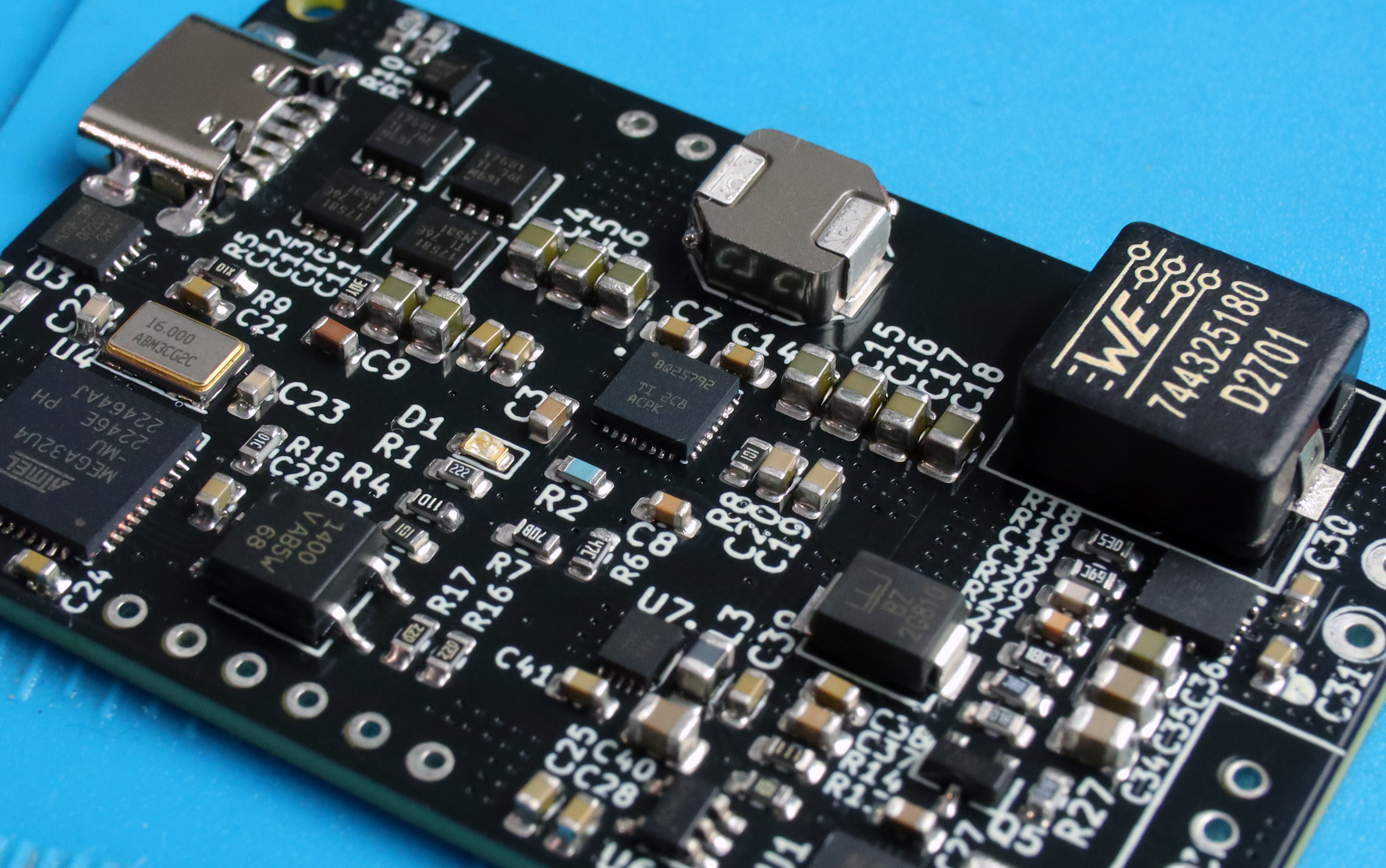
The software for this project is based on this HID power device library: https://github.com/abratchik/HIDPowerDevice
The software is complete and functional, although it could use some polish and some comments. I would recommend changing the "debug" variable in MiniPC_UPS.ino to true before you flash the code for the first time. This will enable debug output and stop the BMS from trying to shut your computer down due to a "Low battery". Once you've confirmed all of the values are being read correctly, you should be safe to go back in and set that variable to false and the BMS will begin functioning.
USB-C PD charging is slow. I found a small issue in the PCB design (which I have now fixed) before uploading that may or may not have solved this problem. I suspect that the issues I've had with this are just down to soldering or faulty hardware because the second charger input works as intended and it is basically identical to the first one after all of the USB PD components. I have checked and the correct values are being requested from the USB charger so the issue has somewhere down the line from the USB PD hardware. This was working for me at one stage, which is why I suspect its an assembly issue.
USB HID is sometimes not detected by windows. This one has been difficult to track down, but I'm certain its a software issue that's causing the problem. A simple restart of the system always seems to rectify the problem so I've left it alone for now.
This is hopefully sorted now. Please let me know if this issue still occurs!
| Qty | Value | Footprint | References |
|---|---|---|---|
| 6 | 0.1uF | Capacitor_SMD:C_0603_1608Metric | C7, C10, C11, C14, C24, C30 |
| 6 | 10uF | Capacitor_SMD:C_0805_2012Metric | C4, C5, C6, C12, C13, C36 |
| 6 | 22uF | Capacitor_SMD:C_0805_2012Metric | C15, C16, C17, C18, C39, C44 |
| 4 | CSD17581Q3A | Parts:Q3A_TEX | Q1, Q2, Q3, Q4 |
| 3 | 1nF | Capacitor_SMD:C_0603_1608Metric | C8, C42, C43 |
| 2 | 100k | Resistor_SMD:R_0603_1608Metric | R3, R13 |
| 2 | 10uF | Capacitor_SMD:C_0603_1608Metric | C19, C20 |
| 2 | 1uF | Capacitor_SMD:C_0603_1608Metric | C25, C26 |
| 2 | 22R | Resistor_SMD:R_0603_1608Metric | R16, R17 |
| 2 | 22pF | Capacitor_SMD:C_0603_1608Metric | C22, C23 |
| 2 | 294 ohm | Resistor_SMD:R_0603_1608Metric | R25, R26 |
| 2 | 4.7uF | Capacitor_SMD:C_0603_1608Metric | C3, C31 |
| 2 | 47nF | Capacitor_SMD:C_0603_1608Metric | C1, C2 |
| 2 | BZT52C12T-7 | Parts:SOD-523_0P9X1P3_ONS | D2, D3 |
| 2 | GND | TestPoint:TestPoint_THTPad_D1.5mm_Drill0.7mm | GND2, GND3 |
| 1 | +5v | TestPoint:TestPoint_Pad_D1.0mm | TP6 |
| 1 | .1uF | Capacitor_SMD:C_0603_1608Metric | C28 |
| 1 | .47uF | Capacitor_SMD:C_0603_1608Metric | C27 |
| 1 | 0.01R | Resistor_SMD:R_2512_6332Metric | R12 |
| 1 | 0.1uF | Capacitor_SMD:C_0603_1608Metric_Pad1.08x0.95mm_HandSolder | C21 |
| 1 | 1.0uF | Capacitor_SMD:C_0603_1608Metric | C29 |
| 1 | 1.2M | Resistor_SMD:R_0603_1608Metric | R21 |
| 1 | 100K | Resistor_SMD:R_0603_1608Metric | R29 |
| 1 | 100ohm | Resistor_SMD:R_0603_1608Metric | R8 |
| 1 | 10k | Resistor_SMD:R_0603_1608Metric | R15 |
| 1 | 10ohm | Resistor_SMD:R_0603_1608Metric_Pad0.98x0.95mm_HandSolder | R9 |
| 1 | 10pF | Capacitor_SMD:C_0603_1608Metric | C33 |
| 1 | 11.1k | Resistor_SMD:R_0603_1608Metric | R14 |
| 1 | 127k | Resistor_SMD:R_0603_1608Metric | R4 |
| 1 | 133k | Resistor_SMD:R_0603_1608Metric | R20 |
| 1 | 16 MHZ | Crystal:Crystal_SMD_5032-4Pin_5.0x3.2mm | Y2 |
| 1 | 1K | Resistor_SMD:R_0603_1608Metric | R23 |
| 1 | 1SS367 | Diode_SMD:D_SOD-323 | D4 |
| 1 | 2.2K | Resistor_SMD:R_0603_1608Metric | R1 |
| 1 | 2.2uF | Capacitor_SMD:C_0603_1608Metric | C9 |
| 1 | 2.2uH | Parts:IND_SPM6530_TDK | L1 |
| 1 | 2.7K | Resistor_SMD:R_0603_1608Metric | R24 |
| 1 | 22nF | Capacitor_SMD:C_0603_1608Metric | C37 |
| 1 | 27k | Resistor_SMD:R_0603_1608Metric | R2 |
| 1 | 2ohm | Resistor_SMD:R_0603_1608Metric | R5 |
| 1 | 3.3uH | Parts:IND_1050-WE-HCI_WRE | L2 |
| 1 | 30.31K | Resistor_SMD:R_0603_1608Metric | R6 |
| 1 | 330pF | Capacitor_SMD:C_0603_1608Metric | C32 |
| 1 | 348K | Resistor_SMD:R_0603_1608Metric | R18 |
| 1 | 49.9K | Resistor_SMD:R_0603_1608Metric_Pad0.98x0.95mm_HandSolder | R11 |
| 1 | 5.1K | Resistor_SMD:R_0603_1608Metric_Pad0.98x0.95mm_HandSolder | R10 |
| 1 | 5.24K | Resistor_SMD:R_0603_1608Metric | R7 |
| 1 | 68.1K | Resistor_SMD:R_0603_1608Metric | R19 |
| 1 | 68uF | Capacitor_THT:CP_Radial_D5.0mm_P2.00mm | C34 |
| 1 | 80.6k | Resistor_SMD:R_0603_1608Metric | R22 |
| 1 | AONR21321 | Parts:DFN8_3x3_EP_AOS | MOSFET2 |
| 1 | ATmega32U4-A | Package_DFN_QFN:QFN-44-1EP_7x7mm_P0.5mm_EP5.15x5.15mm | U4 |
| 1 | BQ25792RQMR | Library:QFN40P400X400X100-29N | U2 |
| 1 | D+ | TestPoint:TestPoint_THTPad_D1.5mm_Drill0.7mm | D+1 |
| 1 | D- | TestPoint:TestPoint_THTPad_D1.5mm_Drill0.7mm | D-1 |
| 1 | DO NOT PLACE | Resistor_SMD:R_0603_1608Metric_Pad0.98x0.95mm_HandSolder | R27 |
| 1 | Do Not Place | Resistor_SMD:R_0603_1608Metric_Pad0.98x0.95mm_HandSolder | R28 |
| 1 | GND | TestPoint:TestPoint_THTPad_D2.0mm_Drill1.0mm | GND1 |
| 1 | GND | TestPoint:TestPoint_Pad_D1.0mm | TP8 |
| 1 | IRLHS2242TRPBF | Parts:PQFN6_2X2_INF | MOSFET1 |
| 1 | LED | LED_SMD:LED_0603_1608Metric | D1 |
| 1 | MAX17261METD+ | Analog Devices:21-0137_T1433+2C_MXM | U1 |
| 1 | MISO | TestPoint:TestPoint_Pad_D1.0mm | TP3 |
| 1 | MOSI | TestPoint:TestPoint_Pad_D1.0mm | TP2 |
| 1 | NCP718xSN330 | Package_TO_SOT_SMD:SOT-23-5 | U6 |
| 1 | PC_Sw1 | TestPoint:TestPoint_THTPad_D1.5mm_Drill0.7mm | TP4 |
| 1 | PC_Sw2 | TestPoint:TestPoint_THTPad_D1.5mm_Drill0.7mm | TP5 |
| 1 | REGN | TestPoint:TestPoint_Pad_D1.0mm | TP12 |
| 1 | RESET | TestPoint:TestPoint_Pad_D1.0mm | TP7 |
| 1 | S4B-EHLFSN | Parts:CONN_S4B-EHLFSN_JST | J2 |
| 1 | SCK | TestPoint:TestPoint_Pad_D1.0mm | TP1 |
| 1 | SMBJ24CA | Parts:SMBJ24CA_LTF | U9 |
| 1 | SYS | TestPoint:TestPoint_Pad_D1.0mm | TP9 |
| 1 | TL4100AF240QG | Parts:SW_TL4100AF240QG | S1 |
| 1 | TPS611781RNWR | Parts:RNW0013A | U5 |
| 1 | UJC-HP-M-G-5-MSMT-TR | Parts:CUI_UJC-HP-M-G-5-MSMT-TR | J3 |
| 1 | USB V+ | TestPoint:TestPoint_Pad_D1.0mm | TP10 |
| 1 | USB V+ | TestPoint:TestPoint_THTPad_D1.5mm_Drill0.7mm | USBV+1 |
| 1 | V+ OUT | TestPoint:TestPoint_THTPad_D2.0mm_Drill1.0mm | VOUT1 |
| 1 | VAC2 | TestPoint:TestPoint_THTPad_D1.5mm_Drill0.7mm | VAC2 |
The 110 most common of 113 parts.
It measures 55 × 35 mm and has 4 copper layers, 1.6 mm thick.
113 parts, built around the ATMEGA32U4-AU, TPS611781RNWR, BQ25792RQMR and MAX17261METD+. The full list of its parts is on this page, with links to each part's symbol and footprint where PCBKit's library has them.
From the dmcke5/MiniPC_BMS repository on GitHub, at the commit this page was made from: the board is KiCad Files/Standalone Mini PC BMS - Rev 1.1.kicad_pcb and its schematic KiCad Files/Standalone Mini PC BMS - Rev 1.1.kicad_sch. PCBKit opens the board in the browser, with nothing to install.
Its repository publishes it under the CERN-OHL-S-2.0 licence: you may reuse it on that licence's terms (keep the author's notice, and for a copyleft licence share your changes alike).
dmcke5/NucDeck
The Open Source DIY Handheld Gaming PC!

LUntiedt/Smart_IOT_PowerBank_PCB
A bidirectional USB-C Power Delivery (PD) power bank built around a software-defined PD stack and an I²C buck-boost charger. This repository holds the KiCad hardware design (schematic, layout, BOM, fabrication outputs).


dmcke5/ZenDeck
This is the second revision of my Mini PC based handheld Gaming PC! It is designed for a Beelink SER 5 Mini PC but could be adapted to other systems by changing the mounting brackets and outlet plate.

Team-Micras/MicrasPCB
Micras micromouse PCBs as code: Zener circuits, KiCad layouts, CI checks and a design portal

TKAman23/AERoS
An All-Encompassing Rocket System (AERoS) currently in development

