4 layers60 × 60 mm
Rocket payload
Gupatron/Gupsfirstpcb
This is the first pcb that I will manufacture and intend to use for teleop usecases in my personal projects.
138 parts

 timdrysdale/atmega-demo
PCB to demonstrate atmega microcontroller
Atmega demo is an open-source printed circuit board by timdrysdale, from the timdrysdale/atmega-demo repository on GitHub, published under the GPL-3.0 licence. It is a 4-layer board of 69.6 × 20.8 mm with 36 parts on 53 nets, routed with 264 tracks and 41 vias.
It is built around the ATMEGA328P-AU, CH340G and PRTR5V0U2X. Its parts include 12 capacitors, 4 resistors, 4 ICs, 4 connectors and 3 diodes. It belongs with the AVR (ATmega, ATtiny) boards of this library.


PCB to demonstrate atmega microcontroller together with ACS712 and temperature sensor.
This board will be used to monitor power consumption and temperature in remote lab boxes.
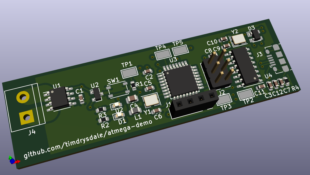
The key components are an Atmega328P, a CH340 USB transceiver, an ACS712 current sensor and a simple analog temperature sensor. DTR reset is enabled to support re-programming over USB, while ICSP header is supplied for initial programming. Both CH340 and Atmega are using 12MHz crystals, which yields 0.1% baud rate error at 57600 baud for the Atmega.
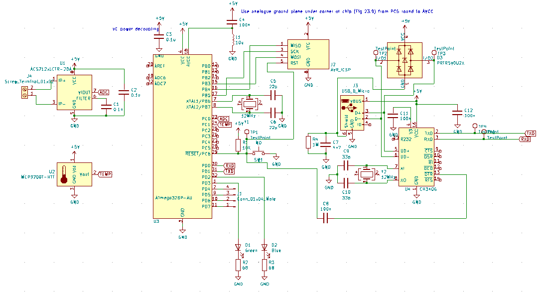
| Comment | Designator | Footprint | LCSC |
|---|---|---|---|
| 0.1n | C1 | Capacitor_SMD:C_0603_1608Metric | C100040 |
| 100n | C8,C11,C12 | Capacitor_SMD:C_0603_1608Metric | C14663 |
| 0.1u | C2,C3 | Capacitor_SMD:C_0603_1608Metric | C14663 |
| 100n | C4 | Capacitor_SMD:C_0805_2012Metric | C49678 |
| 22p | C5,C6 | Capacitor_SMD:C_0603_1608Metric | C1653 |
| 4n7 | C7 | Capacitor_SMD:C_0603_1608Metric | C53987 |
| 33p | C9,C10 | Capacitor_SMD:C_0603_1608Metric | C1663 |
| Green | D1 | LED_SMD:LED_0603_1608Metric | C72043 |
| Blue | D2 | LED_SMD:LED_0603_1608Metric | C72043 |
| PRTR5V0U2X | D3 | Package_TO_SOT_SMD:SOT-143 | C2827688 |
| Conn_01x04_Male | J1 | Connector_PinSocket_2.54mm:PinSocket_1x04_P2.54mm_Vertical | |
| AVR_ICSP | J2 | Connector_PinHeader_2.54mm:PinHeader_2x03_P2.54mm_Vertical | |
| USB_B_Micro | J3 | Connector_USB:USB_Micro-B_Amphenol_10118194_Horizontal | C132563 |
| Screw_Terminal_01x02 | J4 | TerminalBlock:TerminalBlock_bornier-2_P5.08mm | |
| 10u | L1 | Inductor_SMD:L_0805_2012Metric | C1046 |
| 10K | R1 | Resistor_SMD:R_0603_1608Metric | C25804 |
| 68 | R2,R3 | Resistor_SMD:R_0603_1608Metric | C27592 |
| 1M | R4 | Resistor_SMD:R_0603_1608Metric | C22935 |
| NO | SW1 | Button_Switch_SMD:SW_SPST_PTS810 | C116501 |
| TestPoint | TP1,TP2,TP3,TP4,TP5 | TestPoint:TestPoint_Keystone_5015_Micro-Minature | C238130 |
| ACS712xLCTR-20A | U1 | Package_SO:SOIC-8_3.9x4.9mm_P1.27mm | C10681 |
| MCP9700T-HTT | U2 | Package_TO_SOT_SMD:SOT-23 | C150830 |
| ATmega328P-AU | U3 | Package_QFP:TQFP-32_7x7mm_P0.8mm | C14877 |
| CH340G | U4 | Package_SO:SOIC-16_3.9x9.9mm_P1.27mm | C14267 |
| 12MHz | Y1,Y2 | Crystal:Crystal_SMD_3225-4Pin_3.2x2.5mm | C97242 |
The design for manufacture showed a couple of small issues:
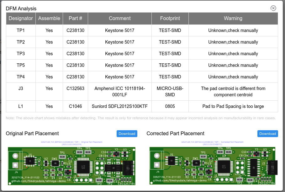
The parts placement as shown on upload (known to disply with incorrect rotations):
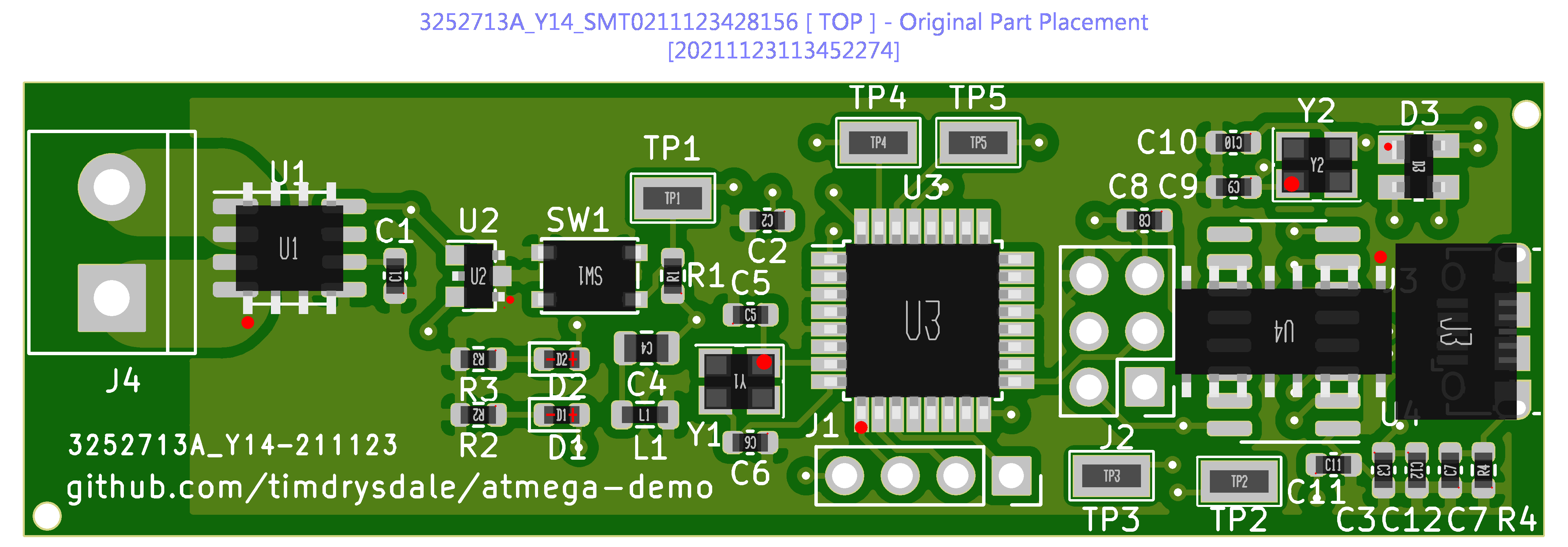
The corrected placement after processing by JLCPCB (parts now oriented the same as the 3D output from KiCAD:
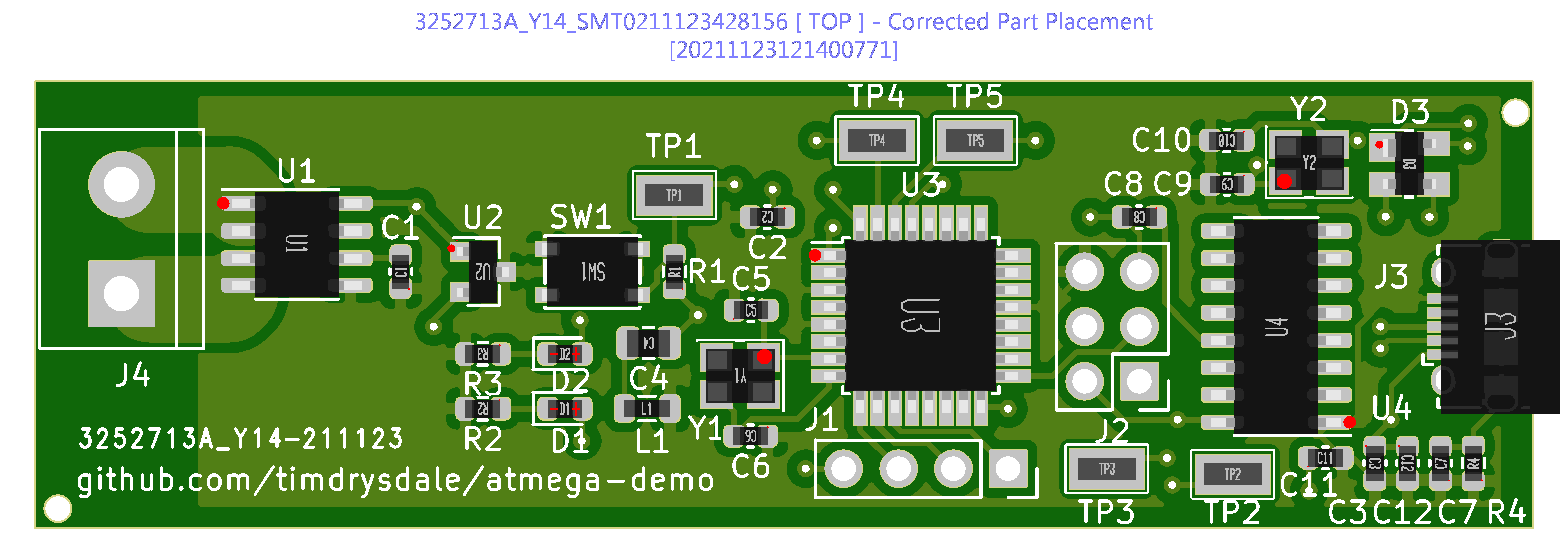
| Qty | Value | Footprint | References |
|---|---|---|---|
| 5 | TestPoint | TestPoint:TestPoint_Keystone_5015_Micro-Minature | TP1, TP2, TP3, TP4, TP5 |
| 3 | 100n | Capacitor_SMD:C_0603_1608Metric | C8, C11, C12 |
| 2 | 0.1u | Capacitor_SMD:C_0603_1608Metric | C2, C3 |
| 2 | 12MHz | Crystal:Crystal_SMD_3225-4Pin_3.2x2.5mm | Y1, Y2 |
| 2 | 22p | Capacitor_SMD:C_0603_1608Metric | C5, C6 |
| 2 | 33p | Capacitor_SMD:C_0603_1608Metric | C9, C10 |
| 2 | 68 | Resistor_SMD:R_0603_1608Metric | R2, R3 |
| 1 | 0.1n | Capacitor_SMD:C_0603_1608Metric | C1 |
| 1 | 100n | Capacitor_SMD:C_0805_2012Metric | C4 |
| 1 | 10K | Resistor_SMD:R_0603_1608Metric | R1 |
| 1 | 10u | Inductor_SMD:L_0805_2012Metric | L1 |
| 1 | 1M | Resistor_SMD:R_0603_1608Metric | R4 |
| 1 | 4n7 | Capacitor_SMD:C_0603_1608Metric | C7 |
| 1 | ACS712xLCTR-20A | Package_SO:SOIC-8_3.9x4.9mm_P1.27mm | U1 |
| 1 | ATmega328P-AU | Package_QFP:TQFP-32_7x7mm_P0.8mm | U3 |
| 1 | AVR_ICSP | Connector_PinHeader_2.54mm:PinHeader_2x03_P2.54mm_Vertical | J2 |
| 1 | Blue | LED_SMD:LED_0603_1608Metric | D2 |
| 1 | CH340G | Package_SO:SOIC-16_3.9x9.9mm_P1.27mm | U4 |
| 1 | Conn_01x04_Male | Connector_PinSocket_2.54mm:PinSocket_1x04_P2.54mm_Vertical | J1 |
| 1 | Green | LED_SMD:LED_0603_1608Metric | D1 |
| 1 | MCP9700T-HTT | Package_TO_SOT_SMD:SOT-23 | U2 |
| 1 | NO | Button_Switch_SMD:SW_SPST_PTS810 | SW1 |
| 1 | PRTR5V0U2X | Package_TO_SOT_SMD:SOT-143 | D3 |
| 1 | Screw_Terminal_01x02 | TerminalBlock:TerminalBlock_bornier-2_P5.08mm | J4 |
| 1 | USB_B_Micro | Connector_USB:USB_Micro-B_Amphenol_10118194_Horizontal | J3 |
Gupatron/Gupsfirstpcb
This is the first pcb that I will manufacture and intend to use for teleop usecases in my personal projects.

vul-os/sirboard
Open hardware: 107 KiCad PCB designs — SMD-to-THT breakout adapters, ATTiny/ATMega/ESP development boards, and a 39-part sensor line on a common JST-SH connector.


4x1md/vx8_gps
DIY GPS module for Yaesu VX-8DR/VX-8DE handheld transceiver.

valerionew/Banana-Random-Number-Generator
Random number generator based on radioactivity from bananas

elVucko/Duino_Coin_AVR
This is the simplest DUINO coin mining board design with four Atmega328p and CH340 connected to the FE1.1S USB hub.

spacebiz24/Thermal-Profiling
A Thermal Profiling Platform built with ATMega328P and MAX31856

ArduProject/PCB_DRONE_C8
En este repositorio encontrareis los archivos de fabricación y las listas de montaje del PCB con STM32F103C8 que hemos visto en el curso.
It measures 69.6 × 20.8 mm and has 4 copper layers, 1.6 mm thick.
36 parts, built around the ATMEGA328P-AU, CH340G and PRTR5V0U2X. The full list of its parts is on this page, with links to each part's symbol and footprint where PCBKit's library has them.
From the timdrysdale/atmega-demo repository on GitHub, at the commit this page was made from: the board is pcb/atmega-demo/atmega-demo.kicad_pcb. PCBKit opens the board in the browser, with nothing to install.
Its repository publishes it under the GPL-3.0 licence: you may reuse it on that licence's terms (keep the author's notice, and for a copyleft licence share your changes alike).