4 layers180.8 × 300.3 mm
Dilemma
Bastardkb/Dilemma
The Dilemma is a vertical stagger low-profile keyboard with mods.
383 parts590

 theonlydesigner/custom-rp2040
at the center of the madness is the RP2040 microcontroller chip which handles all the processing. it is paired with a W25Q128 QSPI flash memory chip for storing firmware and a 12MHz crystal oscillator to provide the…
Half life is an open-source printed circuit board by theonlydesigner, from the theonlydesigner/custom-rp2040 repository on GitHub. It is a 2-layer board of 21 × 51 mm with 37 parts on 54 nets, routed with 489 tracks and 50 vias.
It is built around the RP2040, W25Q128JVSIQ and SK6812MINI-E. Its parts include 17 capacitors, 7 resistors, 4 connectors, 3 ICs and 1 diode. It belongs with the RP2040 boards of this library.


this project is essentially a custom raspberry pi pico clone built from scratch using the hack club stasis devboard guide. instead of buying a ready-made dev board you have to manually route every single trace and place every tiny passive component [because suffering builds character].
at the center of the madness is the RP2040 microcontroller chip which handles all the processing. it is paired with a W25Q128 QSPI flash memory chip for storing firmware and a 12MHz crystal oscillator to provide the clock signal. power is delivered via a USB-C connector featuring 5.1k pull-down resistors so modern power supplies actually negotiate power correctly. an MCP1700 LDO voltage regulator takes that input and steps it down to a stable 3.3V for the system. finally every single GPIO pin is broken out onto dual headers so the board can easily interface with a mini hackpad.
| Part | Quantity | No of items in 1 unit | Price w/o shipping | Price |
|---|---|---|---|---|
| 1uF Capacitor | 1 | 2 | 0.1 | 0.1 |
| 0.1uF Capacitor | 1 | 11 | 0.1 | 0.1 |
| 10uF Capacitor | 1 | 2 | 0.1 | 0.1 |
| 33pF Capacitor | 1 | 2 | 0.2 | 0.2 |
| USB_C_Receptacle_USB2.0_14P | 1 | 1 | 0.3 | 0.3 |
| Conn_01x20 | 1 | 2 | 0.6 | 0.6 |
| Conn_01x03 | 1 | 1 | 0.16 | 0.16 |
| 5.1K Resistor | 1 | 2 | 0.1 | 0.1 |
| 27 Resistor | 1 | 2 | 0.1 | 0.1 |
| 1K Resistor | 1 | 2 | 0.1 | 0.1 |
| 10K Resistor | 1 | 1 | 0.1 | 0.1 |
| SW_Push | 1 | 1 | 0.11 | 0.11 |
| RP2040 Chip | 1 | 1 | 0.84 | 1.3 |
| MCP1700x-330xxTT | 1 | 1 | 0.5 | 0.5 |
| W25Q128JVS | 1 | 1 | 5.02 | 5.02 |
| 12MHz Crystal | 1 | 1 | 0.39 | 0.39 |
| PCB w/ Stencil | 1 | 1 | 6 | 10 |
| Solder Paste | 1 | 1 | 2.3 | 3 |
| Tweezers | 1 | 1 | 1.8 | 1.8 |
| Solder Iron and stuff related to that | 1 | 1 | 3.2 | 3.2 |
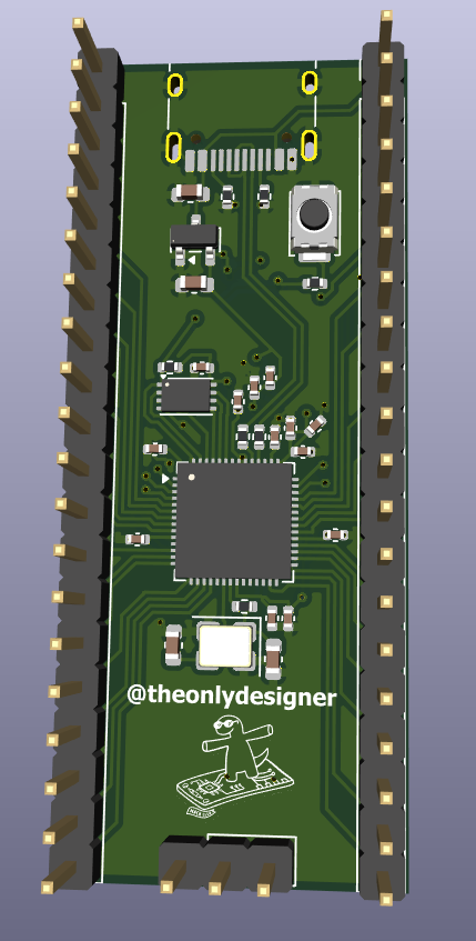 (a gorgeous 3D render of a board that will probably release the magic smoke the second power is applied)
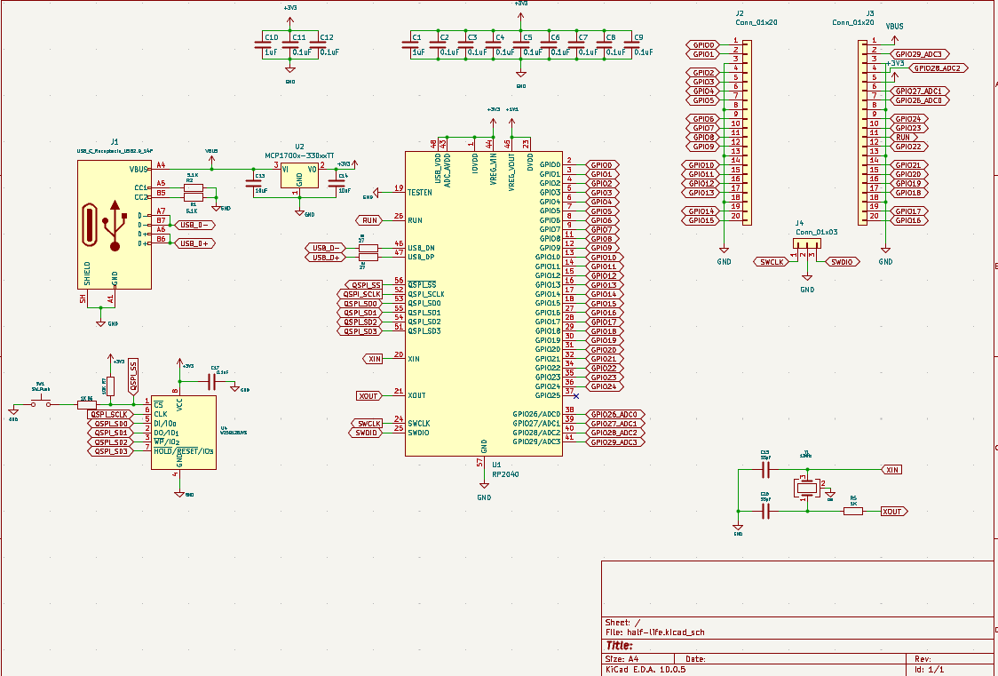 (the schematic page where i stared into the void until the net names started making sense)
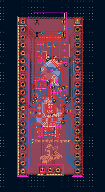 (the actual PCB layout before sending it off to the fab house to be judged)
| Qty | Value | Footprint | References |
|---|---|---|---|
| 11 | 0.1uF | Capacitor_SMD:C_0402_1005Metric | C2, C3, C4, C5, C6, C7, C8, C9, C11, C12, C17 |
| 3 | LOGO | LOGO | G***, G***, G*** |
| 2 | 10uF | Capacitor_SMD:C_0603_1608Metric | C13, C14 |
| 2 | 1K | Resistor_SMD:R_0402_1005Metric | R5, R6 |
| 2 | 1uF | Capacitor_SMD:C_0402_1005Metric | C1, C10 |
| 2 | 27 | Resistor_SMD:R_0402_1005Metric | R3, R4 |
| 2 | 33pF | Capacitor_SMD:C_0603_1608Metric | C15, C16 |
| 2 | 5.1K | Resistor_SMD:R_0402_1005Metric | R1, R2 |
| 2 | Conn_01x20 | Connector_PinHeader_2.54mm:PinHeader_1x20_P2.54mm_Vertical | J2, J3 |
| 1 | 10K | Resistor_SMD:R_0402_1005Metric | R7 |
| 1 | 12MHz | Crystal:Crystal_SMD_3225-4Pin_3.2x2.5mm | Y1 |
| 1 | Conn_01x03 | Connector_PinHeader_2.54mm:PinHeader_1x03_P2.54mm_Vertical | J4 |
| 1 | MCP1700x-330xxTT | Package_TO_SOT_SMD:SOT-23 | U2 |
| 1 | RP2040 | Package_DFN_QFN:QFN-56-1EP_7x7mm_P0.4mm_EP3.2x3.2mm | U1 |
| 1 | SK6812MINI-E | LED_SMD:LED_SK6812MINI-E_3.2x2.8mm_P1.5mm_ReverseMount | LED5 |
| 1 | SW_Push | Button_Switch_SMD:SW_Push_SPST_NO_Alps_SKRK | SW1 |
| 1 | USB_C_Receptacle_USB2.0_14P | Connector_USB:USB_C_Receptacle_HRO_TYPE-C-31-M-12 | J1 |
| 1 | W25Q128JVS | Package_SON:Winbond_USON-8-1EP_3x2mm_P0.5mm_EP0.2x1.6mm | U4 |
Bastardkb/Dilemma
The Dilemma is a vertical stagger low-profile keyboard with mods.

weteor/Qazikat
qaz-like keyboard with offset space, arrow cluster and ISO-enter


yuz207/agentpad13
agentpad13 — open-source 13-key macropad for agentic work (RP2040, vial-qmk, planar joystick, Raw HID agent-status protocol)

defvs/minigeki
A portable implementation of an ONGEKI controller, with all necessary buttons, two macros, RGB LED support, USB-C.

slopus/codex-keybored
A 100% vibe-coded hardware build: Fusion 360, six-layer KiCad PCB, STM32 firmware, and live JLC factory handoff.


BigTuna94/RP2.65-F
RP2.65-F Mechanical Keyboard - a 65% Ortholinear Keyboard with Faders
It measures 21 × 51 mm and has 2 copper layers, 1.6 mm thick.
37 parts, built around the RP2040, W25Q128JVSIQ and SK6812MINI-E. The full list of its parts is on this page, with links to each part's symbol and footprint where PCBKit's library has them.
From the theonlydesigner/custom-rp2040 repository on GitHub, at the commit this page was made from: the board is KiCAD/half-life.kicad_pcb and its schematic KiCAD/half-life.kicad_sch. PCBKit opens the board in the browser, with nothing to install.
Its repository states no licence, so its author keeps all rights: ask theonlydesigner before reusing the design.