2 layers
IgnisV1-TP4056
TehoorMarjan/Ignis
An autonomous flame-shaped lamp/nightlight controlled by microcontroller with WS2812B LED ring and integrated Qi wireless charging. 🔥
11 parts1

 TehoorMarjan/Ignis1
An autonomous flame-shaped lamp/nightlight controlled by microcontroller with WS2812B LED ring and integrated Qi wireless charging. 🔥
IgnisV2 is an open-source printed circuit board by TehoorMarjan, from the TehoorMarjan/Ignis repository on GitHub. It is a 4-layer board with 86 parts on 47 nets, routed with 420 tracks and 67 vias.
It is built around the ATTINY212-SSN, 74LVC1G17GW,125-JSM and FP6277XR-G1, with the BQ24073RGTR, BQ51013BRHLT and FN15X104K160PNG among its other parts. Its parts include 30 capacitors, 20 resistors, 6 diodes, 6 connectors and 5 ICs. It belongs with the lEDs and displays boards and the AVR (ATmega, ATtiny) boards of this library.


An autonomous flame-shaped lamp/nightlight controlled by microcontroller with WS2812B LED ring and integrated Qi wireless charging.
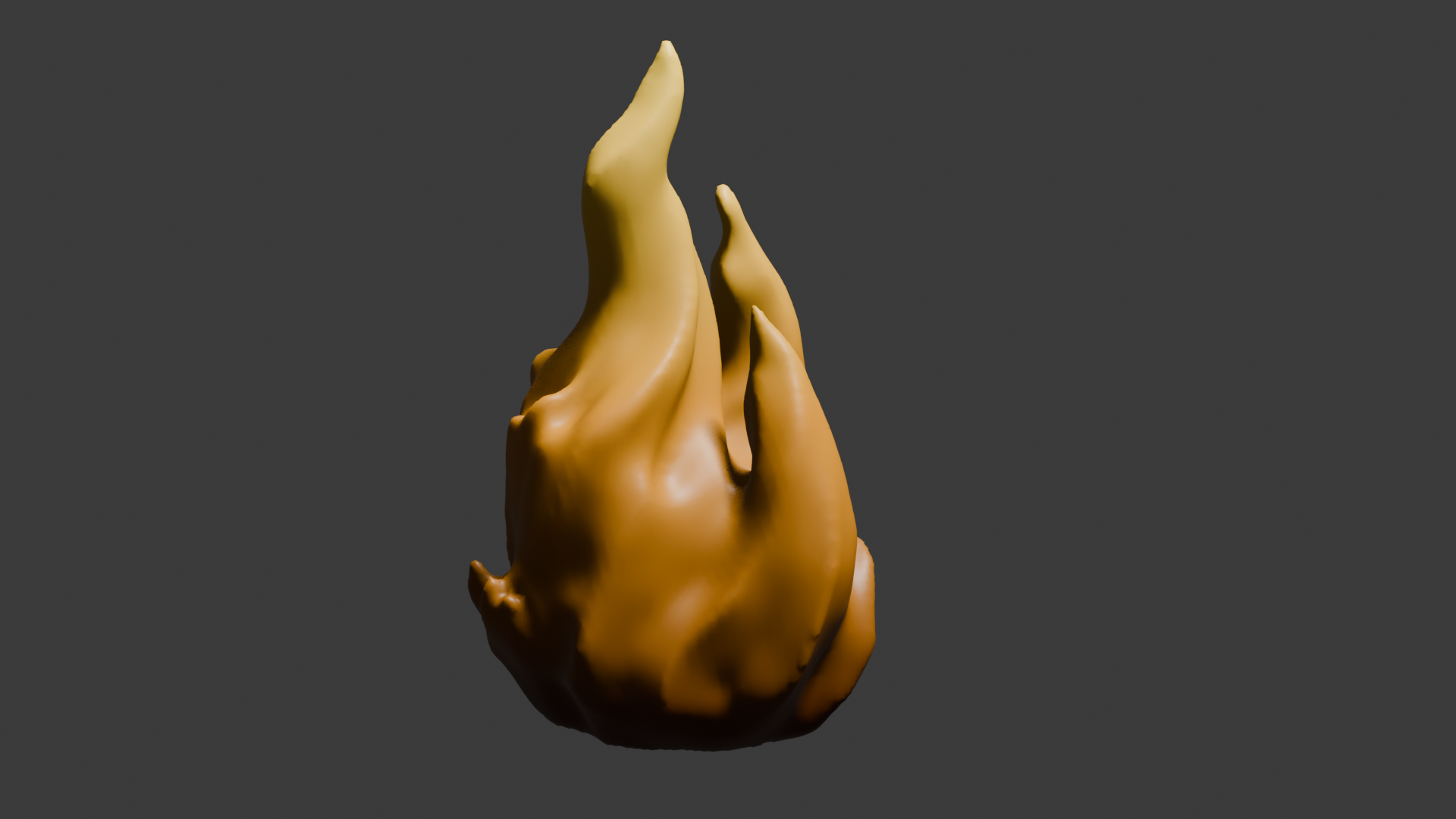
Status : Hardware validated ✅ - Firmware development in progress
Last update : September 2025
flowchart TD
  QiCharger["📡 BQ51013B<br/>Qi Charger"] ==> Charger["🔌 BQ24073<br/>Battery Charger"]
  Charger <==> Battery["🔋 LiPo Battery<br/>320mAh"]
  Charger ==> Boost["⚡ FP6277 Boost<br/>3.7V → 5V"]

  subgraph SYS["System"]
    MCU["🖥️ ATtiny212 @ 20MHz"]
    ShockSensor["💥 SW-18030<br/>Shock Sensor"]
    MCU -. "User Interaction" .- ShockSensor
    MCU --> WS2812B["💡 WS2812B<br/>6 LEDs"]
  end

  Boost ==> SYS
  Charger -. "Charge Status" .-> MCU
QiCharger -. "Coil Status" .-> MCUThis repository contains comprehensive documentation for all aspects of the Ignis project. Navigate to the relevant sections based on your interests:
For Contributors: Start with PROJECT_STATUS.md to understand current progress, then refer to the relevant documentation sections above based on your area of contribution.
| Qty | Value | Footprint | References |
|---|---|---|---|
| 8 | 100n | Capacitor_SMD:C_0402_1005Metric | C14, C16, C24, C25, C26, C27, C28, C29 |
| 6 | 10k | Resistor_SMD:R_0402_1005Metric | R3, R7, R14, R19, R20, R21 |
| 6 | WS2812B | Ignis:LED_WS2812B2020 | D2, D3, D4, D5, D6, D7 |
| 3 | 10u | Capacitor_SMD:C_0402_1005Metric | C12, C13, C15 |
| 3 | 220 | Resistor_SMD:R_0402_1005Metric | R1, R8, R9 |
| 3 | ToolingHole | MountingHole:ToolingHole_1.152mm | H1, H2, H3 |
| 2 | 10n | Capacitor_SMD:C_0402_1005Metric | C6, C7 |
| 2 | 1n | Capacitor_SMD:C_0402_1005Metric | C3, C4 |
| 2 | 22u | Capacitor_SMD:C_1206_3216Metric | C20, C21 |
| 2 | 4.7u | Capacitor_SMD:C_0603_1608Metric | C18, C19 |
| 2 | 470n | Capacitor_SMD:C_0603_1608Metric | C8, C9 |
| 2 | 47n | Capacitor_SMD:C_0402_1005Metric | C10, C11 |
| 1 | 0 | Capacitor_SMD:C_0805_2012Metric_Pad1.18x1.45mm_HandSolder | C5 |
| 1 | 100u | Capacitor_SMD:CP_Elec_5x5.4 | C22 |
| 1 | 150n | Capacitor_SMD:C_0402_1005Metric | C1 |
| 1 | 15n | Capacitor_SMD:C_0402_1005Metric | C2 |
| 1 | 196 | Resistor_SMD:R_0805_2012Metric | R5 |
| 1 | 1M | Resistor_SMD:R_0402_1005Metric | R18 |
| 1 | 1u | Capacitor_SMD:C_0603_1608Metric | C17 |
| 1 | 2.4k | Resistor_SMD:R_0402_1005Metric | R6 |
| 1 | 2.7k | Resistor_SMD:R_0402_1005Metric | R11 |
| 1 | 20k | Resistor_SMD:R_0402_1005Metric | R4 |
| 1 | 220 | Resistor_SMD:R_0805_2012Metric | R2 |
| 1 | 22n | Capacitor_SMD:C_0402_1005Metric | C30 |
| 1 | 24k | Resistor_SMD:R_0402_1005Metric | R10 |
| 1 | 3.3u | Inductor_SMD:L_1008_2520Metric | L1 |
| 1 | 330 | Resistor_SMD:R_0402_1005Metric | R16 |
| 1 | 390k | Resistor_SMD:R_0402_1005Metric | R12 |
| 1 | 470 | Resistor_SMD:R_0402_1005Metric | R17 |
| 1 | 470u | Capacitor_SMD:CP_Elec_6.3x7.7 | C23 |
| 1 | 530480210 | Ignis:CONN02_530480210_MOL | J3 |
| 1 | 74LVC1G17 | Ignis:IC_74LVC1G17GW_125 | U4 |
| 1 | 75k | Resistor_SMD:R_0402_1005Metric | R13 |
| 1 | ATtiny212-SS | Package_SO:SOIC-8_3.9x4.9mm_P1.27mm | U5 |
| 1 | BQ24073RGTR | Ignis:IC_BQ24073RGTR | U2 |
| 1 | BQ51013BRHLT | Ignis:BQ51013BRHLT | U1 |
| 1 | COIL_A | TestPoint:TestPoint_THTPad_D1.5mm_Drill0.7mm | J1 |
| 1 | COIL_A | TestPoint:TestPoint_Pad_D1.0mm | TP1 |
| 1 | COIL_B | TestPoint:TestPoint_THTPad_D1.5mm_Drill0.7mm | J2 |
| 1 | COIL_B | TestPoint:TestPoint_Pad_D1.0mm | TP2 |
| 1 | FP6277XR-G1 | Ignis:SOIC127P599X175-9N | U3 |
| 1 | GND | TestPoint:TestPoint_Pad_D1.0mm | TP6 |
| 1 | GND | TestPoint:TestPoint_THTPad_D1.5mm_Drill0.7mm | J6 |
| 1 | LED_DIN | TestPoint:TestPoint_Pad_D1.0mm | TP12 |
| 1 | SSW | TestPoint:TestPoint_Pad_D1.0mm | TP14 |
| 1 | SSW_RAW | TestPoint:TestPoint_Pad_D1.0mm | TP13 |
| 1 | SW-18030 | Ignis:SW-180 | SW1 |
| 1 | UPDI | TestPoint:TestPoint_THTPad_D1.5mm_Drill0.7mm | J4 |
| 1 | VBAT | TestPoint:TestPoint_Pad_D1.0mm | TP5 |
| 1 | VBATS | Jumper:SolderJumper-3_P1.3mm_Bridged12_RoundedPad1.0x1.5mm | JP1 |
| 1 | VBUS | TestPoint:TestPoint_Pad_D1.0mm | TP3 |
| 1 | VGNDS | Jumper:SolderJumper-3_P1.3mm_Bridged12_RoundedPad1.0x1.5mm | JP2 |
| 1 | VSYS | TestPoint:TestPoint_THTPad_D1.5mm_Drill0.7mm | J5 |
| 1 | VSYS | TestPoint:TestPoint_Pad_D1.0mm | TP7 |
| 1 | ~{CHRG} | TestPoint:TestPoint_Pad_D1.0mm | TP8 |
| 1 | ~{IND} | TestPoint:TestPoint_Pad_D1.0mm | TP4 |
| 1 | ~{PGOOD} | TestPoint:TestPoint_Pad_D1.0mm | TP9 |
86 parts, built around the ATTINY212-SSN, 74LVC1G17GW,125-JSM, FP6277XR-G1 and BQ24073RGTR. The full list of its parts is on this page, with links to each part's symbol and footprint where PCBKit's library has them.
From the TehoorMarjan/Ignis repository on GitHub, at the commit this page was made from: the board is hardware/IgnisV2/IgnisV2.kicad_pcb and its schematic hardware/IgnisV1-TP4056/IgnisV1-TP4056.kicad_sch. PCBKit opens the board in the browser, with nothing to install.
Its repository states no licence, so its author keeps all rights: ask TehoorMarjan before reusing the design.
TehoorMarjan/Ignis
An autonomous flame-shaped lamp/nightlight controlled by microcontroller with WS2812B LED ring and integrated Qi wireless charging. 🔥


jostsalathe/ctfl-rakete-pcb
Converting this sticker desing into a PCB that lights up its flame and lighthouse top from the bottom side using some LEDs and a coin cell battery.

CmdrZin/Educational-Projects
A group of educational projects to promote hardware and software development.


FujiNetWIFI/fujinet-hardware
Schematics and design files for FujiNet hardware

Nicolai-Electronics/tanmatsu-hardware
Hardware design of the Tanmatsu mainboard

Nicolai-Electronics/kami-hardware
Kami is a modernized re-imagining of the SHA2017 epaper badge by Badge.Team.
