MoodLogger
Attribution note: This README (state documentation, roadmap) and the Proposed v1 architecture section were drafted by Claude (Fable 5) on 2026-07-07 and updated as the design converged (part selection finalized 2026-07-10 with Claude (Opus 4.8)), based on the KiCad files in this repo, the project motivation, and the Picoclick-C3 reference project. Sections contributed by Claude are marked with 🤖. Hardware design decisions, part orders, prototypes, and project direction by Silvan Roth.
A tiny, battery-powered button logger. Press one of (at least) four buttons and the device wakes up, appends which button was pressed at what time to a CSV file, and goes back to sleep. To get the data, you plug the device into any USB host (cable or docking station) and it shows up as an ordinary USB flash drive — no companion app, no driver, no cloud. Grab the CSV, done.
Design goals
- ≥ 4 buttons, each press logged as
timestamp, button to a CSV file
- Wake on button press, sleep otherwise — the device spends almost all of its life asleep
- Battery life measured in months: recharging should rarely, ideally almost never, be necessary
- Host-agnostic data access: the device enumerates as USB mass storage (a flash drive), so any OS can read the CSV without extra software
- Accurate timestamps from a dedicated RTC that keeps time even while the MCU sleeps
Current state
Two prototype PCB revisions exist, both built around a Seeed Studio XIAO ESP32-S3 module. They differ only in the RTC chip. Both are functional as prototypes but share one critical flaw (see Known problems).
Common to both boards
- MCU: XIAO ESP32-S3 (U1) — provides USB-C, LiPo charging, and deep sleep
- 4 tactile buttons (SW1–SW4, C&K PTS125) on XIAO pins D0–D3, each with a 10 k pull-up and 1 k series resistor, used as wake-up sources
- I²C RTC on D4/D5 (SDA/SCL)
- CR1216 coin cell (BT1) as RTC backup so time survives even when the main battery is empty
- SPDT slide switch (SW5) in the battery line as a hard power switch
- Main power from a LiPo cell on the XIAO's battery pads
Version A — DS3231 (EmotionTracker_DS32/)
Board silkscreen: EmotionLog v0 8.2025
- DS3231M (U2, SOIC-16): temperature-compensated RTC with internal oscillator — very accurate, no external crystal needed, but comparatively power-hungry
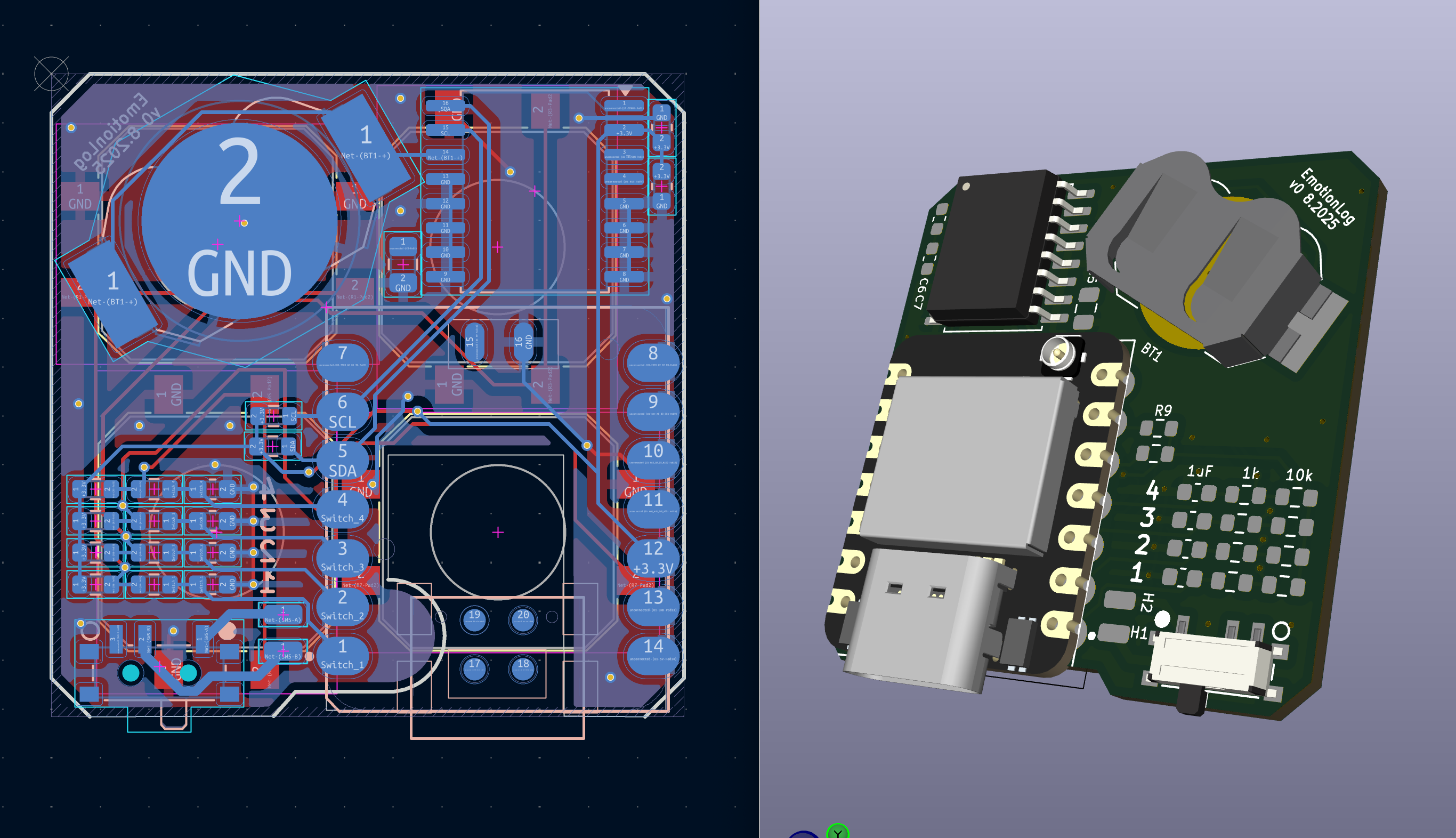
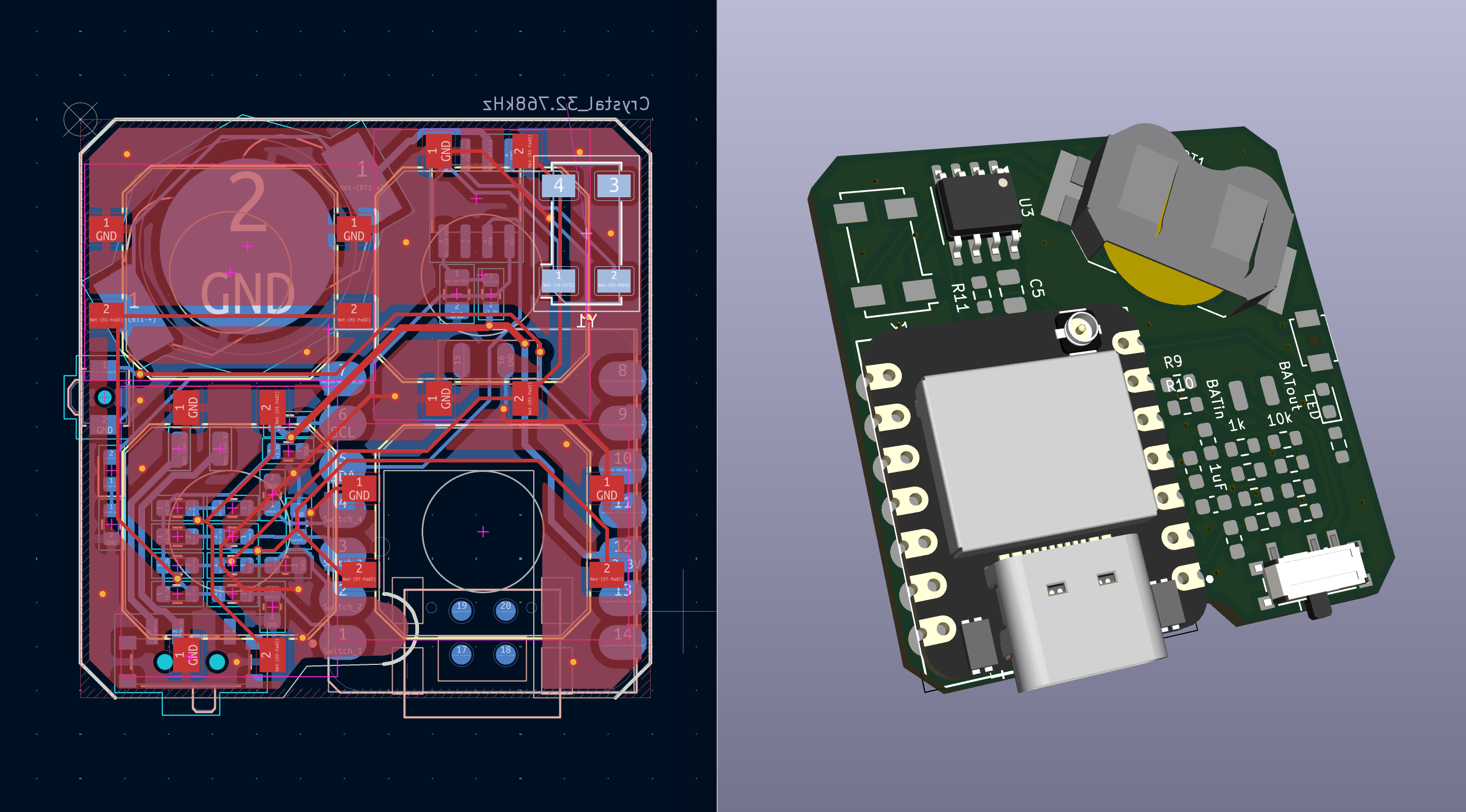
Version B — PCF8523 (EmotionTracker_PCF8523/)
- PCF8523T (U3, SOIC-8) with an external 32.768 kHz crystal (Y1) — much lower current draw than the DS3231, at the cost of needing the crystal and being less accurate over temperature
- Adds a status LED (D1), an extra small push button (SW6), and BATin/BATout solder pads in the battery path for measuring battery current / inserting protection circuitry
Dummy device/ contains a mechanical dummy PCB of the same outline for enclosure fitting
Firmware (Firmware/)
Only a bring-up sketch exists so far: Mood_track_v0/Mood_track_v0.ino is a WS2812B/FastLED color-cycle test. The actual logging firmware (RTC, deep sleep, CSV writing, USB mass storage) has not been written yet.
Known problems
No battery over-discharge protection. The XIAO ESP32-S3 has a charging circuit but no discharge cutoff, so when the device sits unused, the quiescent draw slowly pulls an unprotected LiPo below its safe minimum voltage and permanently damages it. This has already killed one battery. Nothing on either PCB revision protects against this.
The XIAO is oversized for the job. A full ESP32-S3 module with WiFi/BLE is overkill for "log a timestamp and sleep", and its deep-sleep and regulator overhead works against the battery-life goal.
Roadmap
- Software safety first (works on existing boards): monitor battery voltage from firmware and put the device into its lowest-power shutdown state below a cutoff threshold (with hysteresis so it doesn't oscillate near the limit). On the PCF8523 board the BATin/BATout pads can be used to hook up voltage sensing. This only mitigates the problem — even in deepest sleep the board still draws a few µA, so a fully drained device left on the shelf long enough can still damage the cell.
- Hardware protection: add a proper battery protection IC (over-discharge cutoff) to the next board revision, or use protected cells in the meantime.
- Custom v1 design: move away from the XIAO to a leaner MCU (the ATSAMD21G18) with a Picoclick-style soft power latch and native USB mass-storage, designed from the start around the goals above — see Proposed v1 architecture below. Parts are ordered.
Proposed v1 architecture 🤖
Section author: Claude (Fable 5, refined with Opus 4.8), 2026-07-07 / 2026-07-10. Based on the boards above and the Picoclick-C3 reference project (fork in Reference Projects/). Parts are selected and ordered but not yet built or bench-verified — treat as a design proposal, not a validated design.
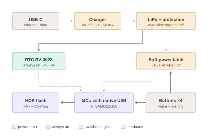
Core idea: soft power latch instead of deep sleep
The key technique to adopt from the Picoclick is its soft-latching power circuit: between presses the MCU is not asleep, it is completely unpowered. A button press physically connects the battery to the regulator; the firmware's first act is to hold that connection via a latch GPIO, it logs the event, then releases the latch and the device switches itself off. The Picoclick C3 reaches < 200 nA idle this way — roughly three orders of magnitude below the XIAO's deep sleep — and it doubles as the discharge-protection strategy: a device that draws almost nothing cannot slowly kill its LiPo. A dedicated protection IC remains as the hard backstop.
Why the ATSAMD21G18 (not the RP2040)
Both were considered — the deciding factor was PCB simplicity for a first custom board that may be partly hand-assembled:
- Leaded package: the SAMD21 is a TQFP-48 (0.5 mm, gullwing leads) — hand-solderable and inspectable. The RP2040 is a QFN-56 (0.4 mm, leadless + thermal pad) that effectively needs stencil + hot-air.
- Fewer mandatory parts: the SAMD21 has 256 KB internal flash and does crystal-less USB (clock recovery off the USB frame), so it needs no boot-flash and no crystal. The RP2040 has no internal flash (external QSPI flash is mandatory just to boot) and needs a 12 MHz crystal.
- Native USB either way: both enumerate cleanly as USB mass storage. (The Picoclick's own ESP32-C3 does not — its USB is a fixed Serial/JTAG peripheral — which is why its MCU was not reused.)
The RP2040 remains a reasonable alternative (faster boot for the latch, larger storage headroom); it just makes the board harder. The nRF52840 is the single-chip option if avoiding external flash matters more than assembly ease.
Chosen parts (ordered)
| Block | Part | Notes |
|---|
| MCU | ATSAMD21G18A (TQFP-48) | 256 KB flash / 32 KB RAM, native USB, crystal-less USB via clock recovery |
| RTC | RV-3028-C7 | ~45 nA, internal crystal, ±1 ppm; runs on the always-on rail so time survives with the MCU off. (DS3231M / PCF8523 are the higher-draw fallbacks proven on the existing boards) |
| Data storage | W25Q32JVSSIM (SOIC-8, 4 MB) | External SPI NOR for the FAT/CSV volume. Chosen over internal-flash-only for write endurance (~100 k vs ~25 k erase cycles) — each logged press is one FAT-metadata write, so endurance, not capacity, is the limit |
| Battery protection | BQ29700DSER | Over-discharge / over-current cutoff — the hard backstop for the failure that killed the prototype battery. Controller only: needs an external dual N-channel MOSFET (e.g. FS8205) in the cell's ground path |
| 3.3 V LDO | AP2112K-3.3 | Sits after the latch, so its ~55 µA quiescent is irrelevant (only powered when the device is awake). Regulates the 3.0–4.2 V cell down to a SAMD21-safe 3.3 V |
| Charger | MCP73831-class | Charge current set by R_prog for the chosen small cell |
| Latch + button OR | P-FET high-side switch + Schottky diode-OR | Clone the Picoclick C3T latch topology (in the submodule) |
Buttons, wake, and logging flow
Each of the four buttons does double duty: all are diode-ORed (Schottky) into the latch enable, so any press powers the board, and each also drives its own sense GPIO with a small RC hold so firmware can still read which button fired after boot. USB VBUS feeds the same latch OR, so plugging into any host wakes the device.
- Log event: boot → grab latch → read RTC over I²C → append
timestamp,button to CSV (FatFs on NOR flash) → release latch.
- USB attached: enumerate as USB MSC exposing the FAT volume; pause logging while mounted.
- Setting the clock without an app: the firmware reads the modification timestamp of a marker file (e.g. the user saves an empty
settime.txt to the drive) — FAT directory entries carry the host's local time, so any OS can set the RTC just by writing a file. Set-on-flash as baseline.
Power budget (estimate)
A log event costs roughly 1 µAh (~30 mA for ~100 ms); 20 presses/day is ~0.5 mAh/month. Standby is dominated by the latch leakage plus the protection IC's quiescent draw (sub-µA). Even a 100 mAh cell lasts multiple years and is realistically limited by self-discharge — with the protection IC cutting the cell off safely at the end instead of destroying it.
Key design notes (SAMD21)
Captured so the board doesn't have to relearn them:
VDDCORE is a regulator output — decouple it to ground with 1 µF and connect nothing else. Tying it to 3.3 V is the classic dead-SAMD21 mistake.- No crystals. Crystal-less USB (enable USBCRM in firmware) plus the external RV-3028 for timekeeping means neither a 12 MHz nor a 32.768 kHz crystal is needed.
- Power the RV-3028 from the raw/always-on rail (ahead of the latch) so it keeps time while the MCU is off; put the I²C pull-ups on the switched 3.3 V so they don't leak from the battery in standby.
- BQ29700 needs external FETs. It's a protection controller — pair it with a dual N-channel MOSFET in the cell's ground path; it does not switch current on its own.
- AP2112K goes after the latch, where its ~55 µA quiescent is a non-issue. Never put it on the always-on rail.
- The latch is the only non-textbook subcircuit — clone the Picoclick C3T topology from the submodule rather than inventing one, and give it enough RC hold to survive the SAMD21 boot time before firmware grabs the latch GPIO.
- Fixed USB/SWD pins: USB D−/D+ on PA24/PA25, SWD on PA30/PA31. I²C and SPI go on any valid SERCOM pads (confirm against the pinmux table).
Repository layout
| Path | Contents |
|---|
EmotionTracker_DS32/ | KiCad 8 project, DS3231 revision (production/ has JLCPCB gerbers, BOM, placement files) |
EmotionTracker_PCF8523/ | KiCad 8 project, PCF8523 revision + mechanical dummy board (production/ as above) |
Firmware/Mood_track_v0/ | Arduino bring-up sketch (LED test only, no logging yet) |
Reference Projects/ | Picoclick-C3-Logger (git submodule, fork of makermoekoe/Picoclick-C3) — reference for the latch circuit and battery protection |
docs/ | Architecture diagrams |
History
The concept was first prototyped on a breadboard with a XIAO ESP32-S3 and a DS3231 RTC module. That prototype worked, but the lack of discharge protection destroyed the battery — which is what motivated the roadmap above.


