
4 layers91 × 53.1 mm
Nff pcb
o7-machinehum/flipper-blackhat
Linux based WiFi pentesting device for the Flipper Zero.
184 parts300

 solderdemon/usb-to-uart
A compact USB-C to 5V UART adapter based on the WCH CH340C.
Usb to uart is an open-source printed circuit board by solderdemon, from the solderdemon/usb-to-uart repository on GitHub. It is a 2-layer board of 18 × 33 mm with 12 parts on 14 nets, routed with 66 tracks and 26 vias.
It is built around the CH340C. Its parts include 5 resistors, 3 diodes, 1 capacitor, 1 IC and 1 connector. It belongs with the interfaces and adapters boards of this library.
A compact USB-C to 5V UART adapter based on the WCH CH340C.
Designed primarily as a direct plug-in serial adapter for retrocomputing systems like the rosco_m68k and rosco_6502, but also works with any 5V microcontroller or serial device using a standard 6-pin header.
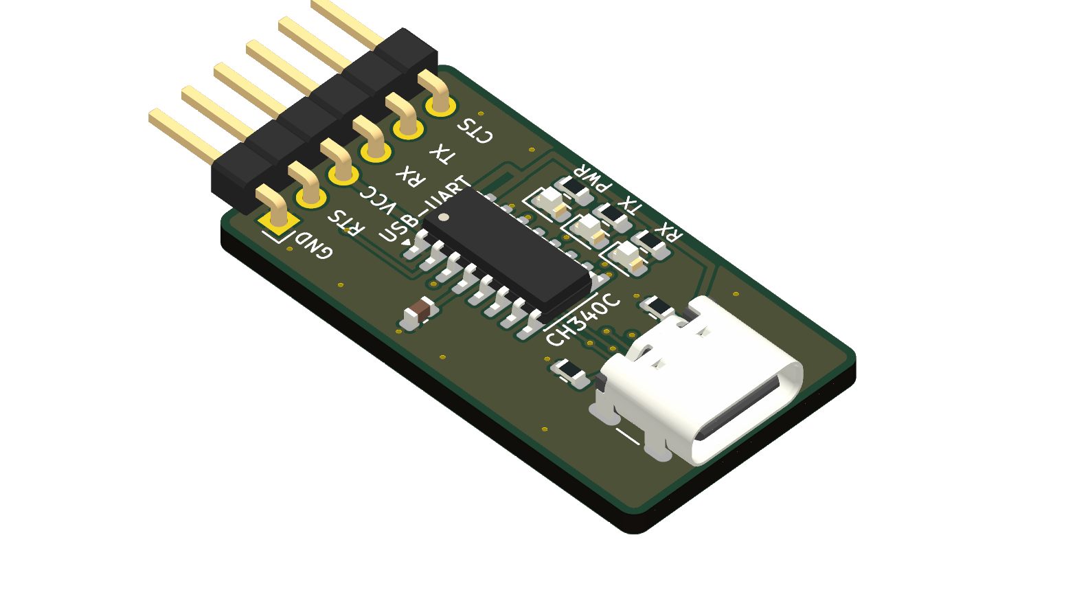
The 6-pin header is labeled on the silkscreen from the perspective of the target board, matching the UART pinout on rosco_m68k and rosco_6502:
| Pin | Silk Label | Adapter Signal (CH340C) | Target Signal (rosco) | Description |
|---|---|---|---|---|
| 1 | GND | GND | GND | Ground (square pad) |
| 2 | RTS | CTS (pin 9, input) | RTS (output) | Flow control from target to PC |
| 3 | VCC | VBUS (5V output) | VCC (5V) | 5V power from USB |
| 4 | RX | TXD (pin 2, output) | RX (input) | Data from PC to target |
| 5 | TX | RXD (pin 3, input) | TX (output) | Data from target to PC |
| 6 | CTS | RTS (pin 14, output) | CTS (input) | Flow control from PC to target |
Note: Because the silkscreen matches the target's pinout, you can plug this adapter directly into a rosco_m68k or rosco_6502 serial header with a 1:1 connection without crossing TX/RX or flow control lines.
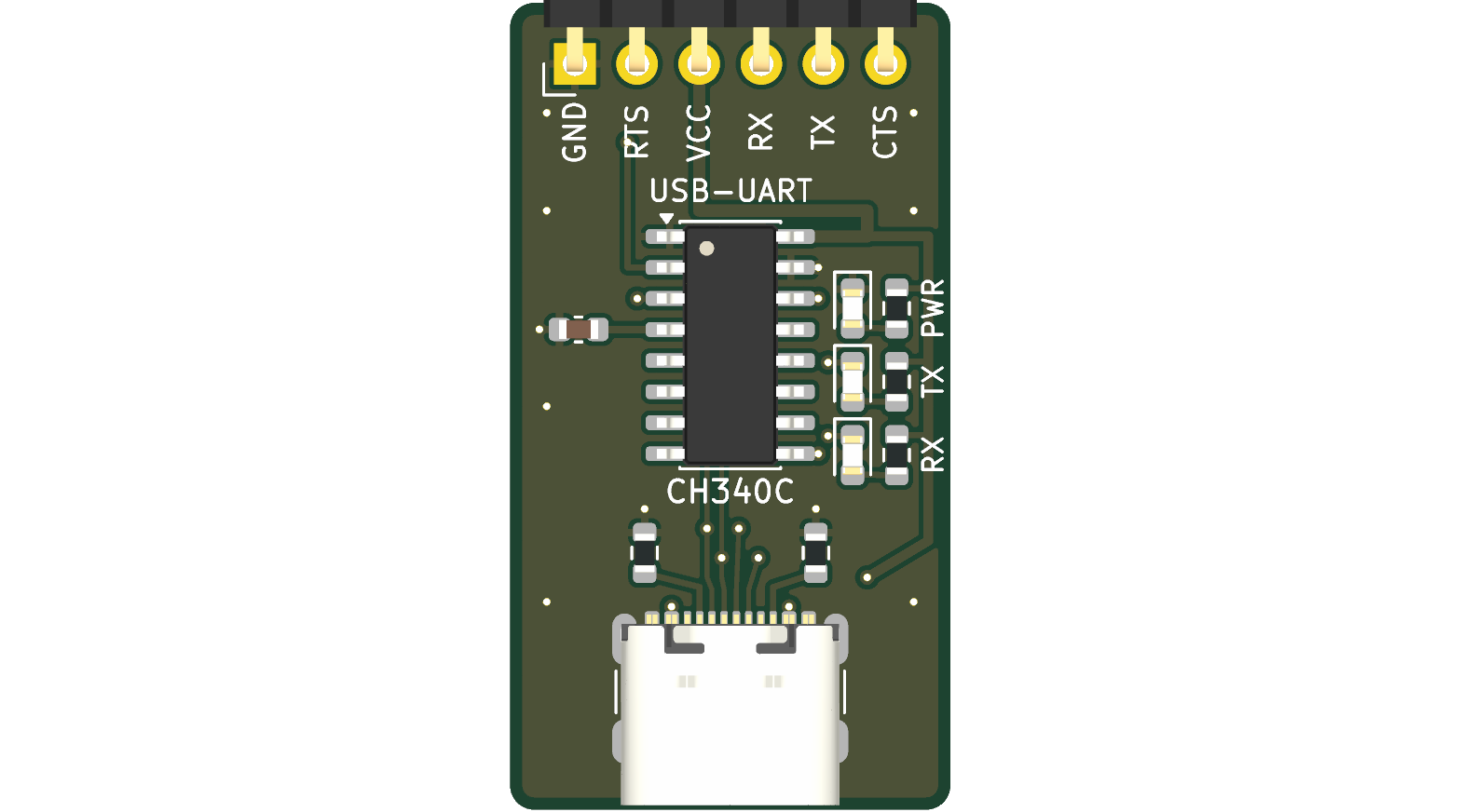
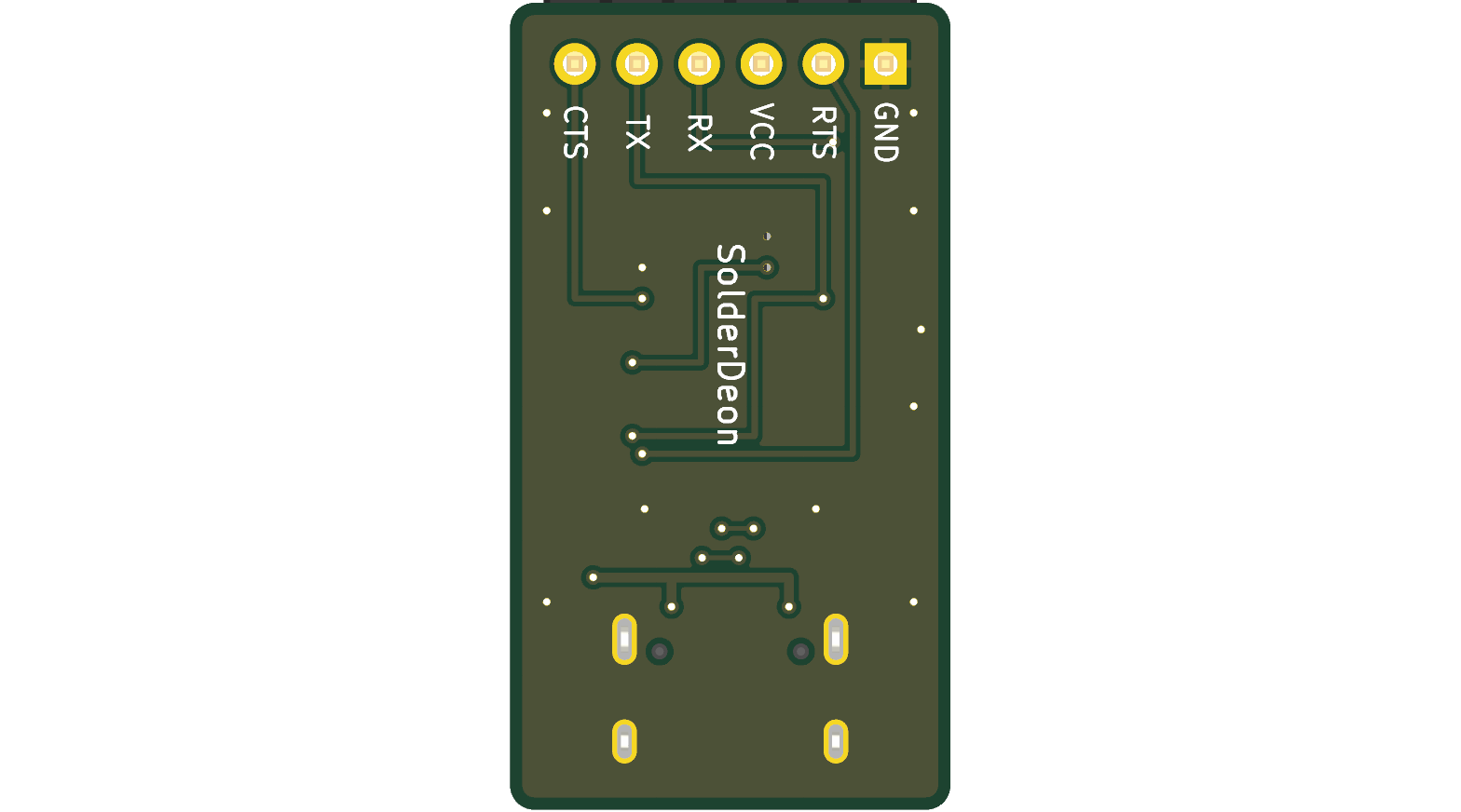
| Top Side | Bottom Side |
|---|---|
 |  |
| Reference | Value | Package / Footprint | Notes |
|---|---|---|---|
| U1 | CH340C | SOIC-16 | USB to serial bridge with internal oscillator |
| J1 | USB-C 14P | TYPE-C-31-M-12 | USB Type-C receptacle (USB 2.0) |
| INPUT | Conn_01x06 | PinHeader 1×06, 2.54 mm | Right-angle pin header |
| C1 | 100 nF | 0603 | VCC / V3 decoupling capacitor |
| R1, R2 | 5.1 kΩ | 0603 | USB-C CC1 / CC2 pull-down resistors |
| R3, R4, R5 | 1 kΩ | 0603 | Current-limiting resistors for LEDs |
| D1, D2, D3 | LED | 0603 | PWR, TX, and RX indicators |
Open Source Hardware (OSHW).
| Qty | Value | Footprint | References |
|---|---|---|---|
| 3 | 1k | R_0603_1608Metric | R3, R4, R5 |
| 2 | 5.1K | R_0603_1608Metric | R1, R2 |
| 1 | 100nF | C_0603_1608Metric | C1 |
| 1 | CH340C | SOIC-16_3.9x9.9mm_P1.27mm | U1 |
| 1 | PWR | LED_0603_1608Metric | D1 |
| 1 | RX | LED_0603_1608Metric | D3 |
| 1 | TX | LED_0603_1608Metric | D2 |
| 1 | UART_A | PinHeader_1x06_P2.54mm_Horizontal | INPUT |
| 1 | USB-C | USB_C_Receptacle_GCT_USB4105-xx-A_16P_TopMnt_Horizontal | J1 |
o7-machinehum/flipper-blackhat
Linux based WiFi pentesting device for the Flipper Zero.


aronreid/ups-to-esp32
Put a USB-only UPS on the network: an ESP32-S3 board and firmware that serves NUT on TCP 3493, with a web UI. No host computer, no Raspberry Pi.

It measures 18 × 33 mm and has 2 copper layers, 1.6 mm thick.
12 parts, built around the CH340C. The full list of its parts is on this page, with links to each part's symbol and footprint where PCBKit's library has them.
From the solderdemon/usb-to-uart repository on GitHub, at the commit this page was made from: the board is main.kicad_pcb and its schematic main.kicad_sch. PCBKit opens the board in the browser, with nothing to install.
Its repository states no licence, so its author keeps all rights: ask solderdemon before reusing the design.