6 layers50 × 50 mm
Xmos xu316
youheng7185/xmos_xu316_cs43131_usb_aud
uac 2.0 on xmos xu316 with cs43131 audio codec
93 parts3

 sneakylizard123-4/MP3player
Why the STM32H743: it has the RAM to buffer audio enough peripherals that almost every feature ended up on its own bus and 480MHz means I never have to care about optimization.
MP3player is an open-source printed circuit board by sneakylizard123-4, from the sneakylizard123-4/MP3player repository on GitHub. It is a 6-layer board of 50 × 70 mm with 150 parts on 181 nets, routed with 1,458 tracks and 241 vias.
It is built around the STM32H743VIT6, SI4735-D60-GU and BME680, with the CS43131-CNZR, TPS613222ADBV and BQ24090DGQR among its other parts. Its parts include 60 capacitors, 27 resistors, 17 switches, 12 ICs and 10 diodes. It belongs with the STM32 boards of this library.


50x75mm mp3 player with am and fm radio
seems like fun also radio stuff
Why the STM32H743: it has the RAM to buffer audio enough peripherals that almost every feature ended up on its own bus and 480MHz means I never have to care about optimization.
Working on splitting this into two boards. The main board keeps the MCU, SD card, buttons, and OLED; the audio/power board takes the DAC, radio, microphone, charging, and the analog rails. It's early in the split: the single-board layout below is what's designed so far, and I'm still shuffling what goes where between the two. Might need to fix power stage to make it a 1-sided board
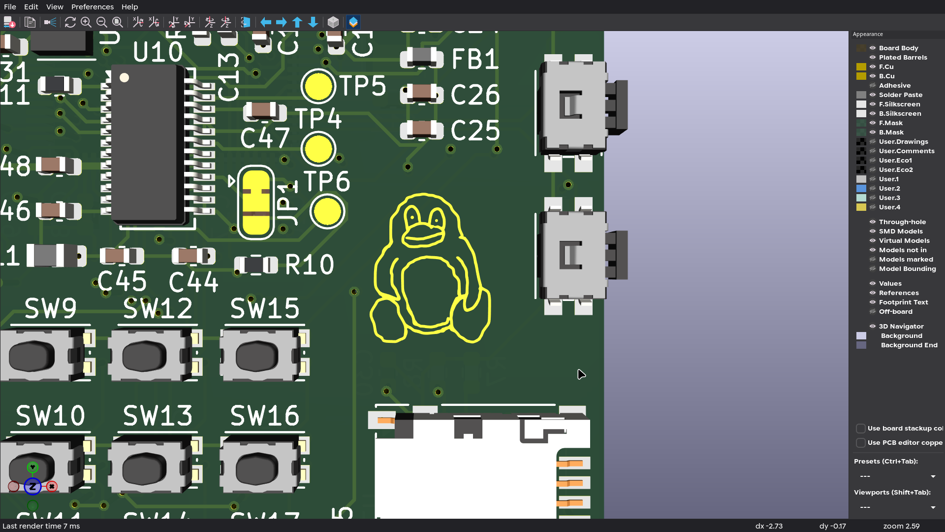
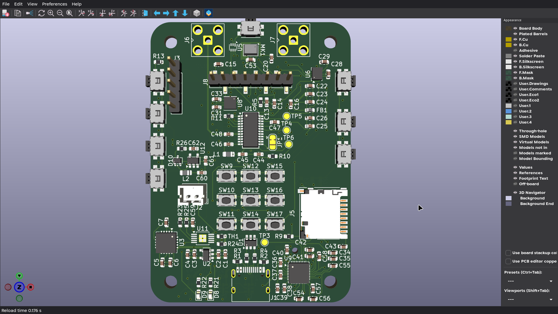 |
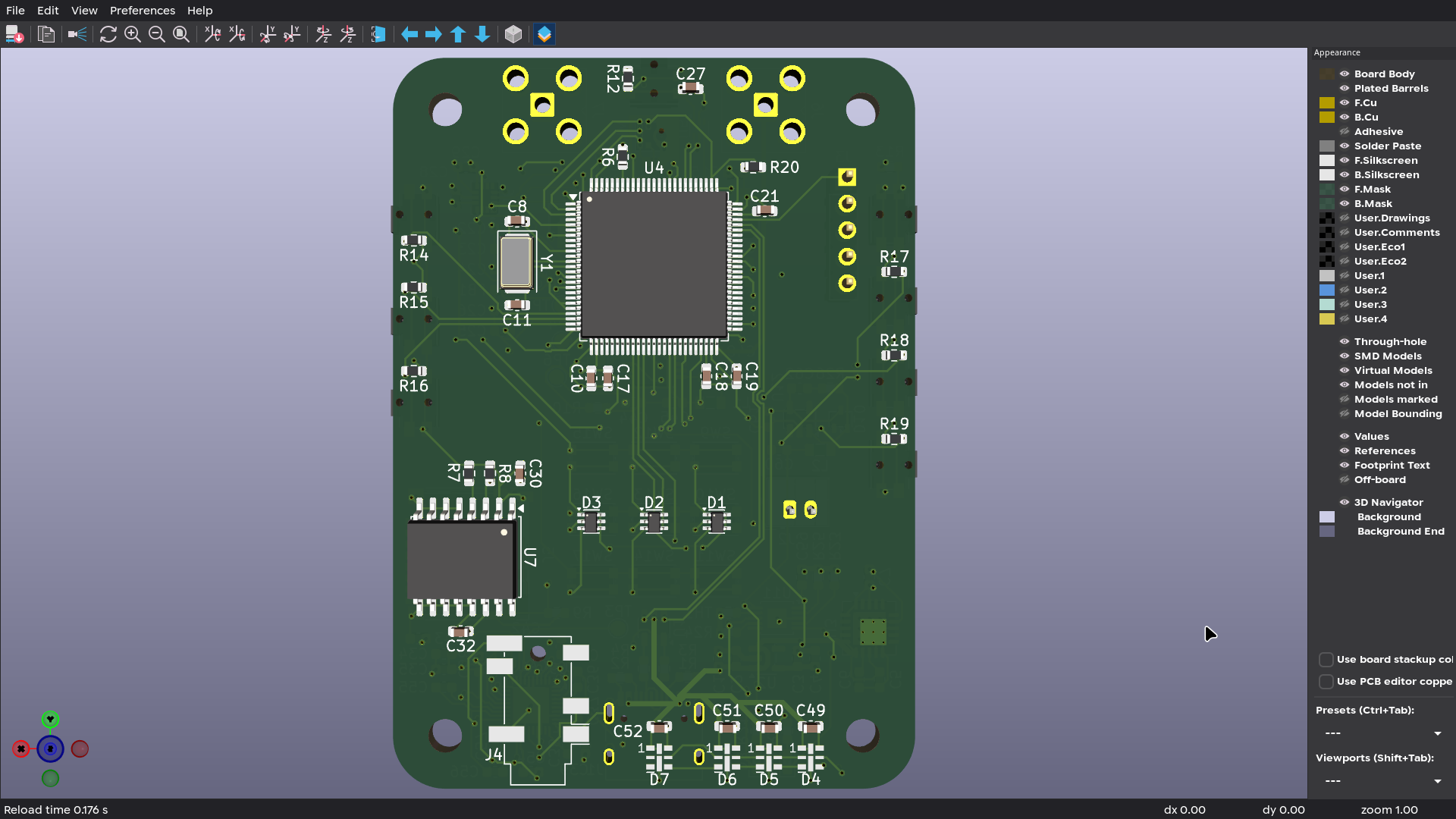
Audio
Storage and controls
Sensors
Power
Strictly speaking none of these have anything to do with playing music. They're in the design because a player that reacts to its surroundings is more interesting than one that doesn't:
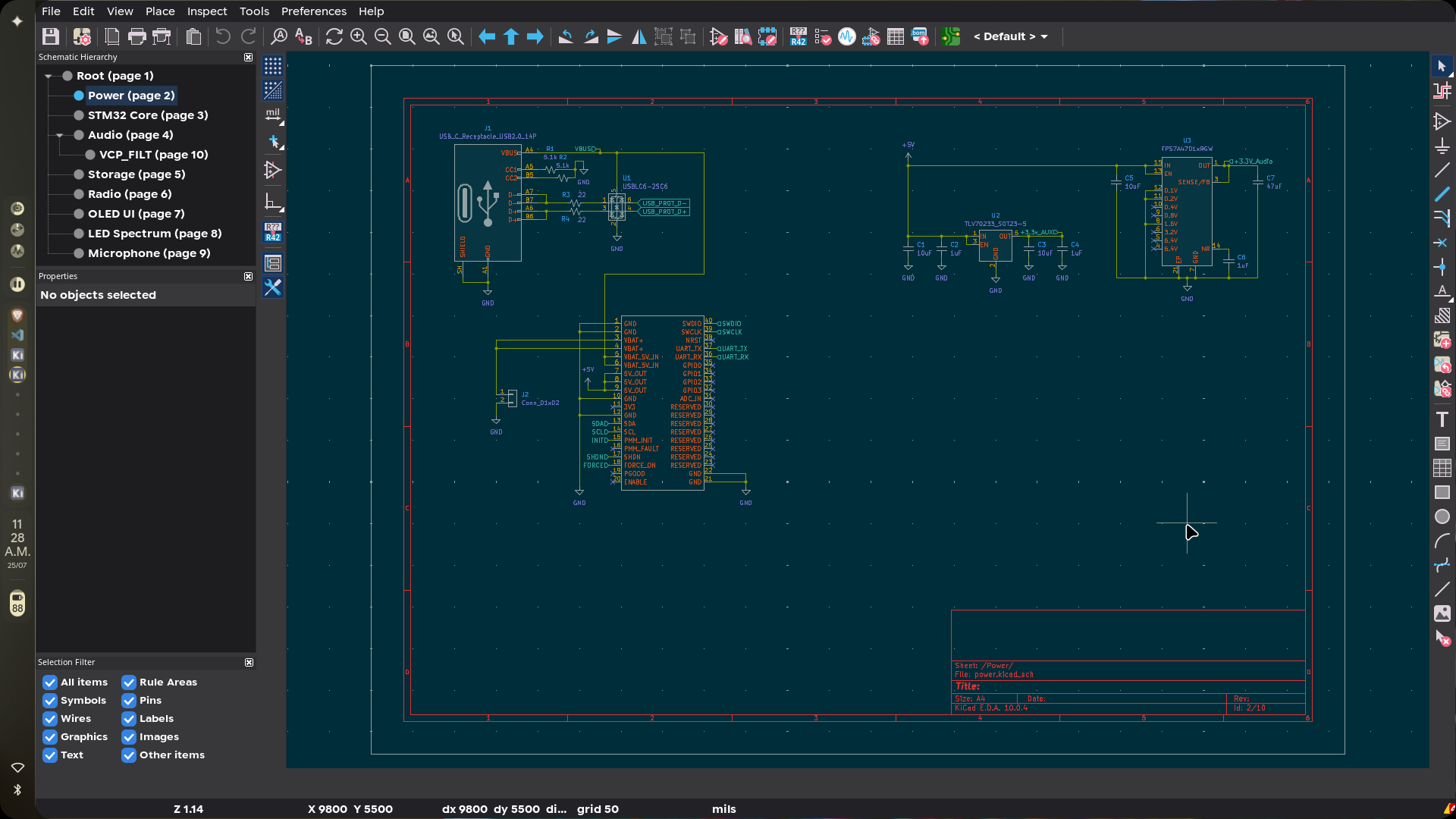
Everything runs off a single Li-ion cell. There are three rails downstream of it: one for digital logic, one for the LEDs, and a quiet one for audio. The BQ24090DGQ takes USB input, manages charging, watches pack temperature through an NTC thermistor, and drives the charge status LEDs. From the battery, a TPS613222ADBV boost converter produces 5V for the LEDs and peripherals, a TLV70233 LDO makes the 3.3V digital rail, and a TPS7A4701 low-noise LDO feeds the audio section on its own.
Power flow:
USB-C
  |
  +-- USBLC6 ESD protection
  |
  +-- BQ24090DGQ Li-ion charger
          |
          +-- Li-ion battery
                  |
                  +-- TPS613222ADBV boost converter
                  |       |
                  |       +-- 5V rail (LEDs and peripherals)
                  |
                  +-- TLV70233 LDO
                  |       |
                  |       +-- 3.3V digital rail
                  |
                  +-- TPS7A4701 low-noise LDO
                          |
                          +-- audio rail
Why three rails? the boost converter switches at a few MHz and I really did not want that showing up in my headphones. Same reason the DAC gets its own regulator.
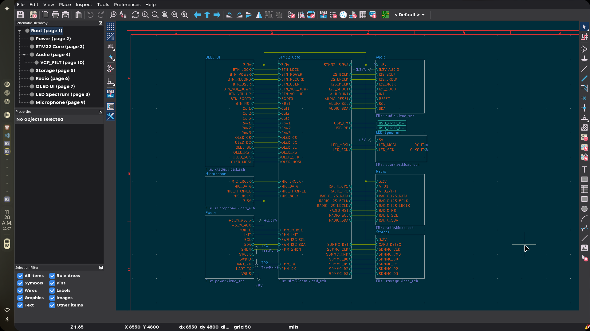
The design is split across hierarchical KiCad sheets:
| Sheet | File | Description | Main Components |
|---|---|---|---|
| Root | MP3player.kicad_sch | Top-level wiring | STM32H743, LSM6DSL, BME680, ISL29035, DS3231M |
| STM32 Core | stm32core.kicad_sch | MCU, sensors, clock | STM32H743, LSM6DSL, BME680, ISL29035, DS3231M |
| Power | power.kicad_sch | Charger + all three rails | BQ24090DGQ, TPS613222ADBV, TPS7A4701, TLV70233, USBLC6 |
| Audio | audio.kicad_sch | DAC, headphone amp, charge pump caps | CS43131-CNZR |
| Storage | storage.kicad_sch | SDMMC bus | MicroSD socket |
| OLED UI | oledui.kicad_sch | Button matrix + direct controls | OLED, button matrix, GPIO controls |
| Radio | radio.kicad_sch | FM receiver + antenna switching | Si4735-D60-GU |
| Microphone | microphone.kicad_sch | MEMS mic on I2S | ICS-43434 MEMS microphone |
| LED Spectrum | ledspectrum.kicad_sch | 70 APA102 LEDs daisy-chained | APA102-2020 LEDs |
Six layers, 1.6mm thick, roughly 50×70mm. I kept the analog audio away from the digital stuff and the switching regulators as much as I could. DAC sits right next to the headphone jack to keep those traces short. I was careful about return paths under the charger and boost converter to keep the switching noise contained.
Designed for standard SMT assembly. The order I use:
Lives in firmware/, PlatformIO project on the STM32 HAL. Right now it brings up the hardware: 480MHz clock from the 8MHz crystal via PLL, GPIO, the I2C/SPI/UART buses, SD card interface, control pins. Playback, the UI, radio control, recording, and the LED effects don't exist yet. That's the next chunk of work.
You'll need PlatformIO (CLI or VS Code extension) and an ST-Link, CMSIS-DAP, or J-Link debugger.
cd firmware
pio run
Flashing over SWD:
pio run -t upload| Ref | Part | Qty | Package | Description |
|---|---|---|---|---|
| U4 | STM32H743VIT6 | 1 | LQFP-100 | Main microcontroller |
| U9 | CS43131-CNZR | 1 | QFN-40 | Audio DAC |
| U10 | Si4735-D60-GU | 1 | SSOP-24 | FM radio receiver |
| MK1 | ICS-43434 | 1 | LGA | I2S MEMS microphone |
| U6 | LSM6DSL | 1 | LGA-14 | 6-axis IMU |
| U8 | BME680 | 1 | LGA-8 | Environmental sensor |
| U5 | ISL29035 | 1 | DFN-6 | Ambient light sensor |
| U7 | DS3231M | 1 | SOIC-16W | Real-time clock |
| U11 | BQ24090DGQ | 1 | HVSSOP-10 | Li-ion charger |
| U12 | TPS613222ADBV | 1 | SOT-23-5 | Boost converter |
| U3 | TPS7A4701xRGW | 1 | VQFN-20 | Low-noise audio regulator |
| U2 | TLV70233 | 1 | SOT-23-5 | 3.3V digital regulator |
| U1 | USBLC6-2SC6 | 1 | SOT-23-6 | USB ESD protection |
| D4-D7 | APA102-2020 | 4 | 2×2mm | RGB LEDs |
| D1-D3 | ACDSV6-4448TI-G | 3 | SOT-363 | Button ESD protection |
| D10 | BAT54W | 1 | SOT-323 | Schottky diode |
| D8-D9 | 0603 LEDs | 2 | 0603 | Status LEDs |
| J1 | HRO TYPE-C-31-M-12 | 1 | USB-C | Charging and USB |
| J4 | PJ31060-I | 1 | — | 3.5mm headphone jack |
| J5 | Hirose DM3D-SF | 1 | — | MicroSD socket |
| J6-J7 | Amphenol 901-143 | 2 | SMA | Antenna connectors |
| J2 | JST PH B2B-PH-K | 1 | 2.0mm | Battery connector |
| J3 | SWD header | 1 | 2.54mm | Debug connector |
| J8 | OLED header | 1 | 2.54mm | Display connector |
| L1 | 450µH | 1 | 0805 | Radio antenna matching |
| L2 | 2.2µH | 1 | 0805 | Boost converter inductor |
| Y1 | 8MHz TXC AA08000002 | 1 | 5032 | MCU crystal |
| SW1-SW17 | Tactile switches | 17 | — | User controls |
| TH1 | 10k NTC | 1 | 0603 | Battery temperature monitoring |
| FB1 | 600Ω @100MHz ferrite | 1 | 0603 | Noise filtering |
BOM.csv has supplier part numbers, links, and pricing for everything above.
Gerbers are in kicad/production/MP3player.zip
Boards and stencils come from JLCPCB.
PCB specs:
| Specification | Value |
|---|---|
| Layers | 6 |
| Dimensions | 50×70mm |
| Thickness | 1.6mm |
| Material | FR-4 TG155 |
| Surface finish | ENIG |
| Outer copper | 1oz |
| Inner copper | 0.5oz |
| PCB color | Purple |
| Silkscreen | White |
Stencil specs:
| Specification | Value |
|---|---|
| Quantity | 2 |
| Sides | Top and bottom |
| Manufacturing process | Laser-cut stainless steel |
| Finish | Electropolished |
| Coating | Nano-coating |
Firmware currently only does hardware init. Still to write:
| Qty | Value | Footprint | References |
|---|---|---|---|
| 17 | 100nF | Capacitor_SMD:C_0603_1608Metric | C13, C16, C19, C23, C26, C27, C28, C29, C30, C31, C32, C33, C34, C35, C41, C43 +1 |
| 16 | 10k | Resistor_SMD:R_0603_1608Metric | R5, R6, R7, R8, R9, R10, R12, R13, R14, R15, R16, R17, R18, R19, R20, TH1 |
| 11 | 0.1uF | Capacitor_SMD:C_0603_1608Metric | C10, C14, C15, C17, C20, C44, C45, C49, C50, C51, C52 |
| 10 | 2.2uF | Capacitor_SMD:C_0603_1608Metric | C18, C21, C38, C39, C40, C54, C55, C56, C57, C58 |
| 9 | SW_Push | Button_Switch_SMD:SW_Push_1P1T_NO_CK_KMR2 | SW9, SW10, SW11, SW12, SW13, SW14, SW15, SW16, SW17 |
| 8 | SW_Push | Button_Switch_SMD:Panasonic_EVQPUM_EVQPUD | SW1, SW2, SW3, SW4, SW5, SW6, SW7, SW8 |
| 6 | 1uF | Capacitor_SMD:C_0603_1608Metric | C2, C4, C6, C24, C25, C59 |
| 4 | APA102-2020 | LED_SMD:LED-APA102-2020 | D4, D5, D6, D7 |
| 4 | MountingHole | MountingHole:MountingHole_3.2mm_M3 | H1, H2, H3, H4 |
| 4 | TestPoint | TestPoint:TestPoint_Pad_D1.5mm | TP3, TP4, TP5, TP6 |
| 3 | 10uF | Capacitor_SMD:C_0603_1608Metric | C1, C3, C5 |
| 3 | ACDSV6-4448TI-G | Package_TO_SOT_SMD:SOT-363_SC-70-6 | D1, D2, D3 |
| 2 | 1.1k | Resistor_SMD:R_0603_1608Metric | R23, R25 |
| 2 | 1.5k | Resistor_SMD:R_0603_1608Metric | R21, R22 |
| 2 | 12pF | Capacitor_SMD:C_0603_1608Metric | C8, C11 |
| 2 | 15uF | Capacitor_SMD:C_0603_1608Metric | C36, C37 |
| 2 | 1nF | Capacitor_SMD:C_0603_1608Metric | C46, C48 |
| 2 | 22 | Resistor_SMD:R_0603_1608Metric | R3, R4 |
| 2 | 4.7uF | Capacitor_SMD:C_0603_1608Metric | C42, C60 |
| 2 | 5.1k | Resistor_SMD:R_0603_1608Metric | R1, R2 |
| 2 | LED | LED_SMD:LED_0603_1608Metric | D8, D9 |
| 2 | SMA | Connector_Coaxial:SMA_Amphenol_901-143_Horizontal | J6, J7 |
| 1 | 10nF | Capacitor_SMD:C_0603_1608Metric | C22 |
| 1 | 11k | Resistor_SMD:R_0603_1608Metric | R24 |
| 1 | 120pF | Capacitor_SMD:C_0603_1608Metric | C62 |
| 1 | 2.2uH | Inductor_SMD:L_0805_2012Metric | L2 |
| 1 | 22nF | Capacitor_SMD:C_0603_1608Metric | C47 |
| 1 | 22uF | Capacitor_SMD:C_0603_1608Metric | C61 |
| 1 | 450uH | Inductor_SMD:L_1206_3216Metric | L1 |
| 1 | 47uF | Capacitor_SMD:C_0603_1608Metric | C7 |
| 1 | 5.11R | Resistor_SMD:R_0603_1608Metric | R26 |
| 1 | 600 | Resistor_SMD:R_0603_1608Metric | R11 |
| 1 | 600R @ 100MHz | Inductor_SMD:L_0603_1608Metric | FB1 |
| 1 | 8MHz TXC AA08000002 | Crystal:Crystal_SMD_5032-2Pin_5.0x3.2mm | Y1 |
| 1 | AudioJack3_Ground_SwitchTR | Connector_Audio:Jack_3.5mm_PJ31060-I_Horizontal | J4 |
| 1 | BAT54W | Package_TO_SOT_SMD:SOT-323_SC-70 | D10 |
| 1 | BME680 | Package_LGA:Bosch_LGA-8_3x3mm_P0.8mm_ClockwisePinNumbering | U8 |
| 1 | BQ24090DGQ | Package_SO:HVSSOP-10-1EP_3x3mm_P0.5mm_EP1.83x1.89mm | U11 |
| 1 | CS43131-CNZR | Package_DFN_QFN:TQFN-40-1EP_5x5mm_P0.4mm_EP3.5x3.5mm | U9 |
| 1 | Conn_01x02 | Connector_JST:JST_PH_B2B-PH-K_1x02_P2.00mm_Vertical | J2 |
| 1 | Conn_01x05 | Connector_PinHeader_2.54mm:PinHeader_1x05_P2.54mm_Vertical | J3 |
| 1 | Conn_01x08 | Connector_PinHeader_2.54mm:PinHeader_1x08_P2.54mm_Vertical_SMD_Pin1Right | J8 |
| 1 | DS3231M | Package_SO:SOIC-16W_7.5x10.3mm_P1.27mm | U7 |
| 1 | ICS-43434 | Sensor_Audio:InvenSense_ICS-43434-6_3.5x2.65mm | MK1 |
| 1 | ISL29035 | OptoDevice:Renesas_DFN-6_1.5x1.6mm_P0.5mm | U5 |
| 1 | LOGO | logo:linuxpenguin-mask | G*** |
| 1 | LOGO | logo:linuxpenguin_cu | G*** |
| 1 | LSM6DSL | Package_LGA:LGA-14_3x2.5mm_P0.5mm_LayoutBorder3x4y | U6 |
| 1 | Micro_SD_Card_Det2 | Connector_Card:microSD_HC_Hirose_DM3D-SF | J5 |
| 1 | STM32H743VIT6 | Package_QFP:LQFP-100_14x14mm_P0.5mm | U4 |
| 1 | Si4735-D60-GU | Package_SO:SSOP-24_3.9x8.7mm_P0.635mm | U10 |
| 1 | SolderJumper_3_Bridged12 | Jumper:SolderJumper-3_P1.3mm_Bridged12_RoundedPad1.0x1.5mm | JP1 |
| 1 | TLV70233_SOT23-5 | Package_TO_SOT_SMD:SOT-23-5 | U2 |
| 1 | TPS613222ADBV | Package_TO_SOT_SMD:SOT-23-5 | U12 |
| 1 | TPS7A4701xRGW | Package_DFN_QFN:Texas_RGW0020A_VQFN-20-1EP_5x5mm_P0.65mm_EP3.15x3.15mm_ThermalVias | U3 |
| 1 | USBLC6-2SC6 | Package_TO_SOT_SMD:SOT-23-6 | U1 |
| 1 | USB_C_Receptacle_USB2.0_14P | Connector_USB:USB_C_Receptacle_HRO_TYPE-C-31-M-12 | J1 |
youheng7185/xmos_xu316_cs43131_usb_aud
uac 2.0 on xmos xu316 with cs43131 audio codec


sneakylizard123-4/Mega2560plus
Mega 2560+ is an upgraded version of the Arduino Mega 2560. It keeps the same form factor and pinout as the original so it still works with every Mega shield, but it adds an onboard sensor suite and an ESP32-S3…

LadyRoninEngineer/Si473x
Data Supporting development of Si473x series radios


ngc6589/Si4735_Radio_RaspberryPiPico
Raspberry Pi Pico とタッチ液晶で Si4735 DSP ラジオを作成しました


EthicalEarth/Radio_SI4735_v1.0_stable
Stable final release of DSP Radio based on si4735 chip.
It measures 50 × 70 mm and has 6 copper layers, 1.6 mm thick.
150 parts, built around the STM32H743VIT6, SI4735-D60-GU, BME680 and CS43131-CNZR. The full list of its parts is on this page, with links to each part's symbol and footprint where PCBKit's library has them.
From the sneakylizard123-4/MP3player repository on GitHub, at the commit this page was made from: the board is kicad/MP3player.kicad_pcb and its schematic kicad/MP3player.kicad_sch. PCBKit opens the board in the browser, with nothing to install.
Its repository states no licence, so its author keeps all rights: ask sneakylizard123-4 before reusing the design.