4 layers12.3 × 13.7 mm

 Person-0/PicoDAC2
A USB-C to 3.5mm HiFi mini DAC
PicoDAC is an open-source printed circuit board by Person-0, from the Person-0/PicoDAC repository on GitHub. It is a 4-layer board of 35.1 × 58.3 mm with 46 parts on 57 nets, routed with 427 tracks and 119 vias.
It is built around the 74AHCT1G125GV, CS43131-CNZR and PCA9306DCUR, with the XTPS7A2018-XC, SK6812SMINI-ER and CC0402KRX7R7BB104 among its other parts. Its parts include 18 capacitors, 9 resistors, 9 diodes, 6 ICs and 1 connector. It belongs with the audio and music boards and the RP2350 boards of this library.


USB-C to 3.5mm HiFi mini DAC
Fully custom PCB and 3D printed case.
Note that a specially cut transparent acrylic sheet will be used as the top lid of the main PCB case which will be superglued to part of the case that is non-detachable.
The main PCB case also requires this 2.5X8 screw that will be used to attach the detachable part with the non-detachable part.
As for the case of the board - 2, since it really is just two directly connected USB-C plugs, the top and bottom part of the case will be glued together after seating the board-2 PCB inside it properly (after testing it).
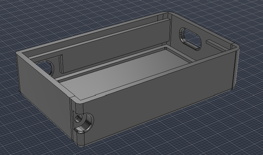
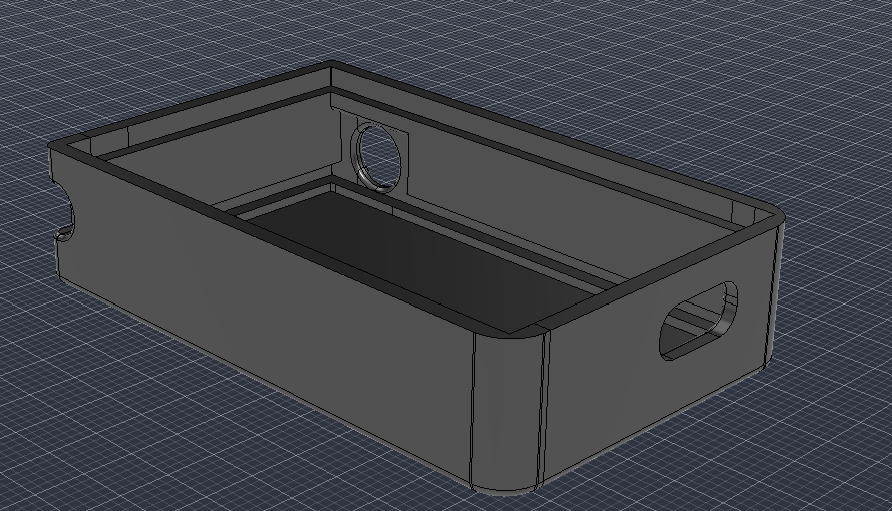
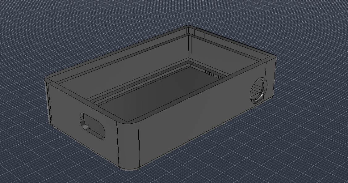
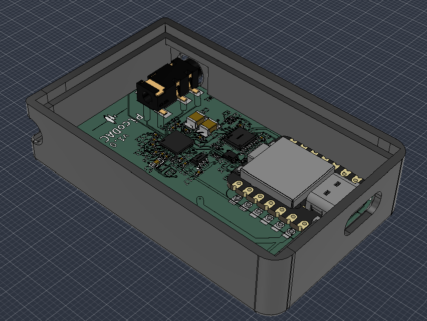
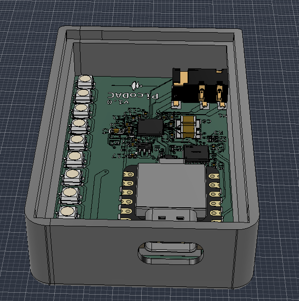
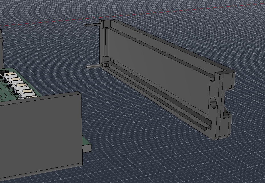
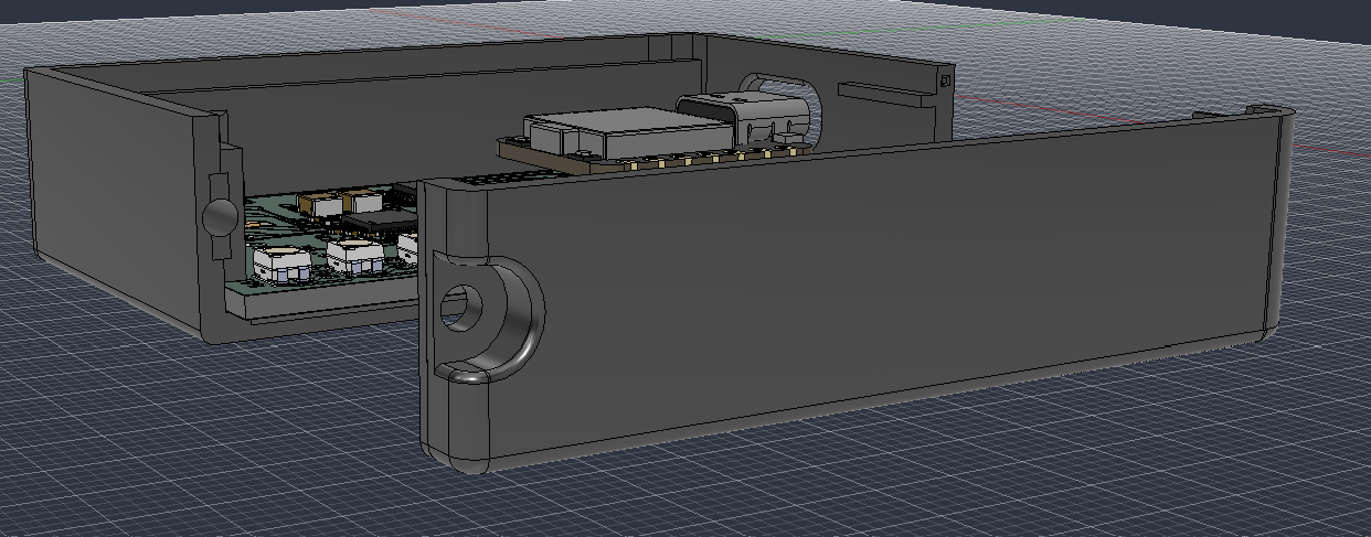
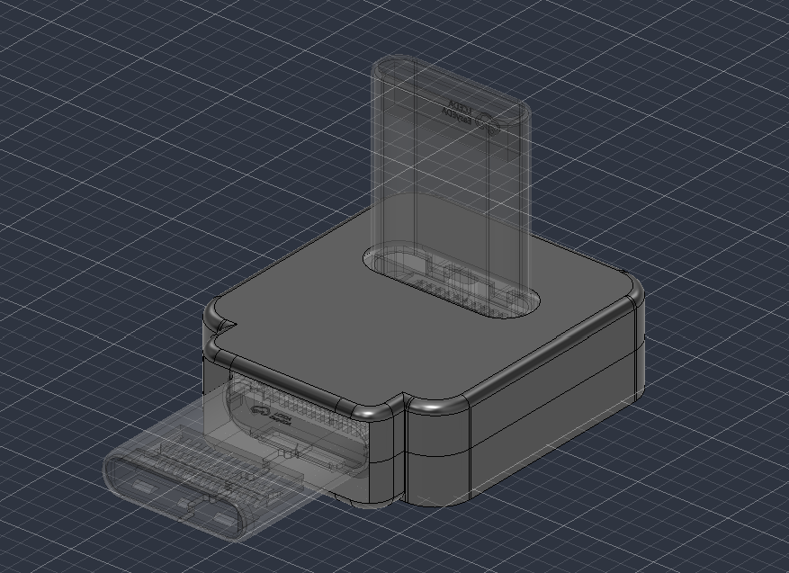
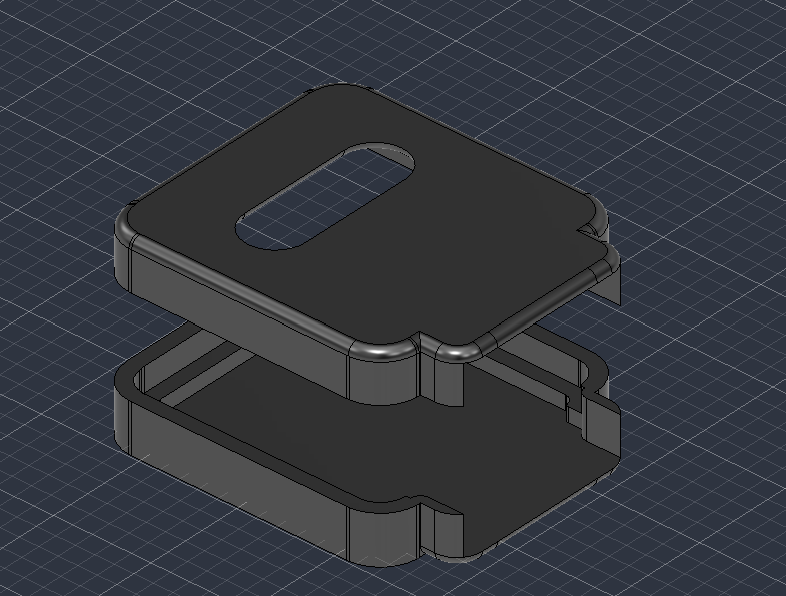
All the design files are available in the CAD folder.
Exported STEP files for 3d-printing are available in /CAD/exports.
Also note that the files:
1_PicoDAC_Case_DetachablePart.step
2_PicoDAC_Case_Main.step
3_board2_top_case.step
4_board2_bottom_case.step
need to be printed as separate bodies.
All these files are also available in.stlformat inside the CAD/exports/stl_files directory.
I recently bought a cheap USB-C to 3.5mm DAC and it was working perfectly fine until it broke.
I use my phone in bed a lot (yes i know this is a bad habit) vertically with the bottom of my phone resting on my chest. Since the USB-C port is at the bottom of my phone, anything connected to it has to do the heavy lifting of keeping the phone upright.
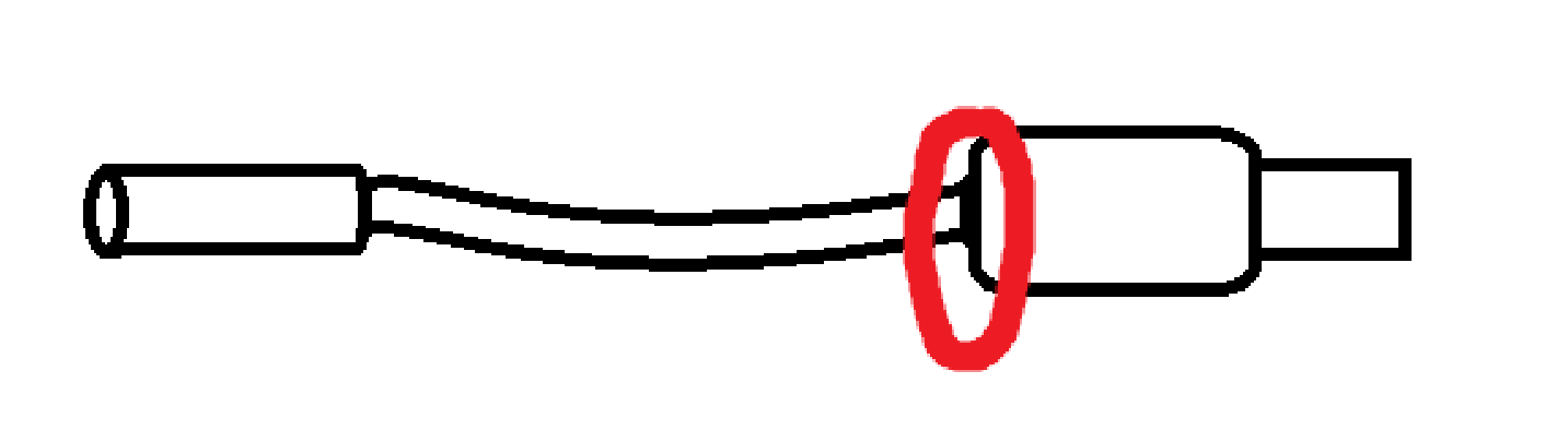
Naturally, the red part I've highlighted in the image slowly got bent and broke :(
To fix this issue, learn more about audio electronics, engineer a cool device and also make a higher-quality DAC in the process, I've started this project.
Main hardware components are:
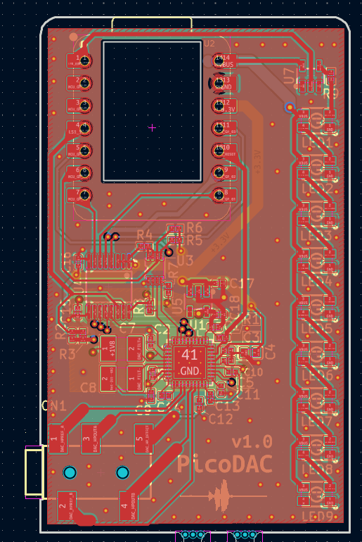
PCB Preview:
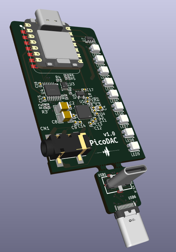
The complete schematics look like:
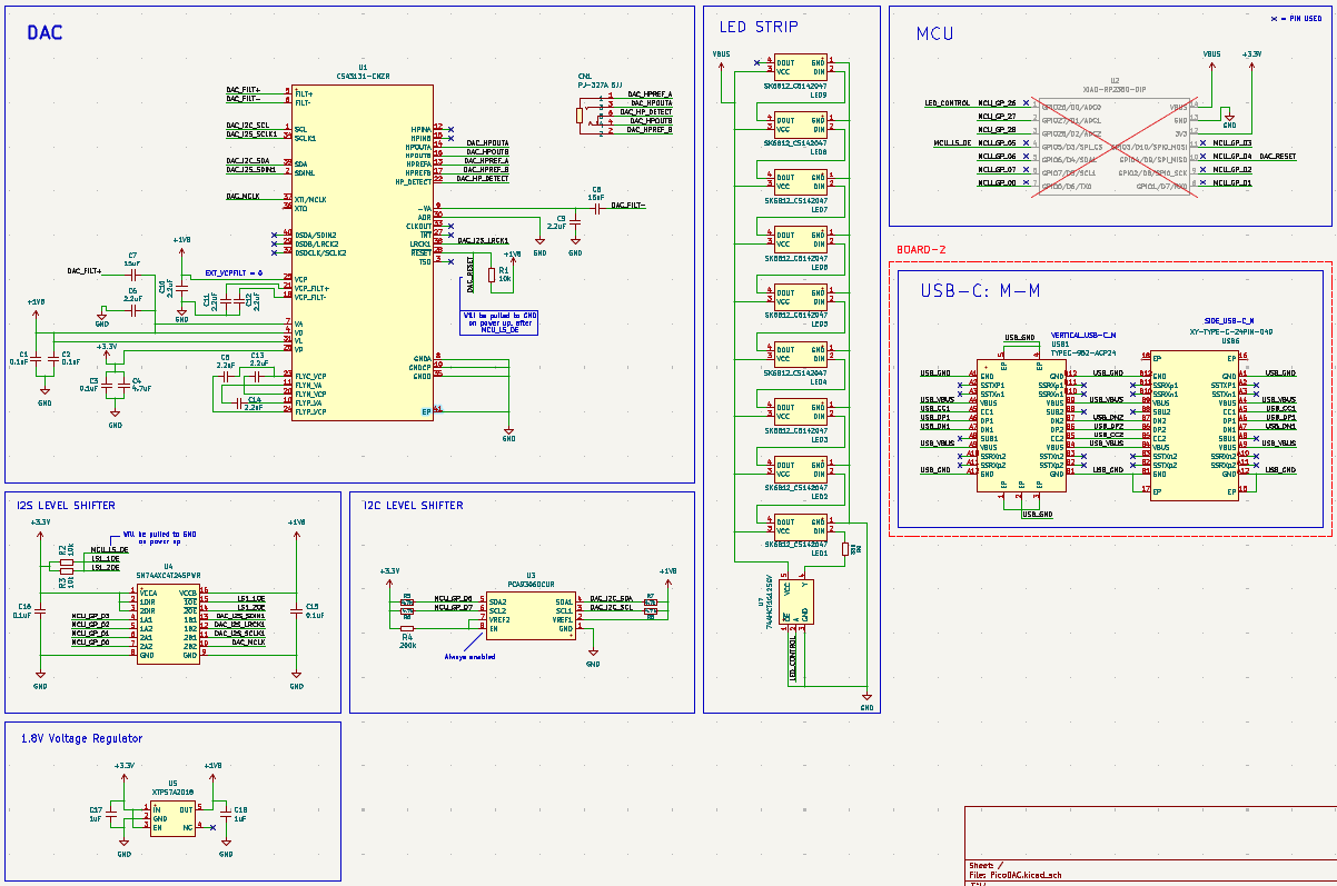
Main Board:
Board 2:
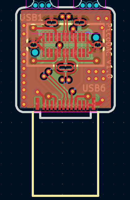
Note that the PCB and schematic files can be opened using KiCAD. They are located in the
/hardware/PicoDACdirectory and/hardware/usbc_m2mdirectory inside this repository.
Steps for viewing the PCB schematics and layout:
PicoDAC.kicad_prousbc_m2m.kicad_proCheckout the firmware directory for the firmware README.md file and current status. It contains building, flashing instructions and also some special notes that might help with the process.
I will be using JLCPCB along with their PCB Assembly service to get this PCB built assembled as it is the cheapest and best option available in my region.
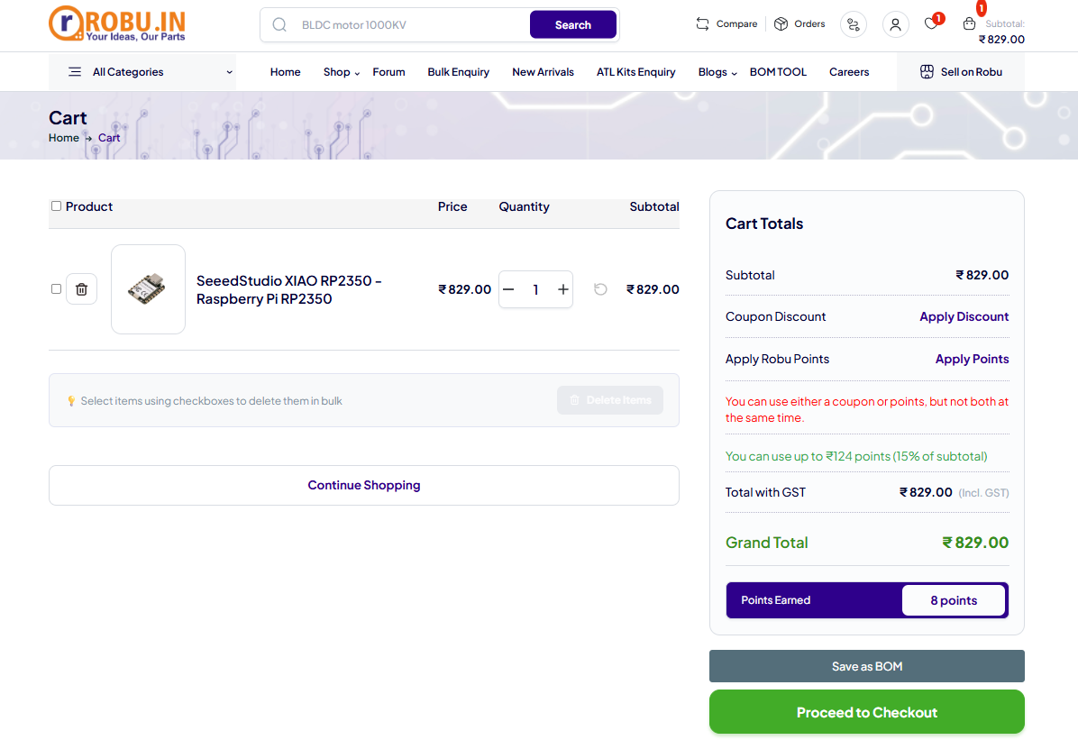
Other than that, the only extra part is the XIAO RP2350 MCU which is available on robu.in.
Note that the following PCB, PCBA costs are for 5 PCBs out of which 2 are assembled (this is the MOQ for JLCPCB) and also I have used basic components instead of extended wherever possible to reduce costs.
| S.No | Name | Description | Qty | Product URL | Effective Cost ($) |
|---|---|---|---|---|---|
| 1 | JLCPCB_PCB | PCB | 1 | ~ | 7.00 |
| 2 | JLCPCB_Assembly | PCB Assembly | 1 | ~ | 68.03 |
| 3 | JLCPCB_Shipping | Lowest price shipping: UPS Worldwide Express Saver | 1 | ~ | 9.10 |
| 4 | JLCPCB_Coupons | ~ | 1 | ~ | -10.00 |
| 5 | SeeedStudio XIAO RP2350 | MCU: XIAO RP2350 | 1 | robu.in/... | 8.69 |
| 6 | Shipping for SeeedStudio XIAO RP2350 | Standard Shipping for XIAO RP2350 | 1 | ~ | 0.51 |
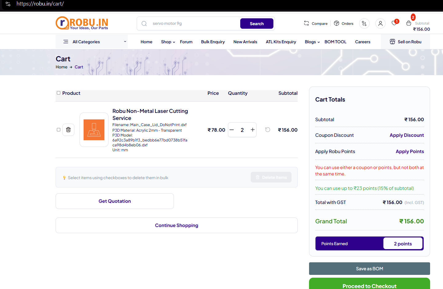
| 5 | Acrylic Lid for Main Case | Acrylic Laser Cutout (Qty = 2 as cost per piece is below 80INR and robu.in requires minimum cost to be atleast 80INR for non-metal laser cutting service order) | 2 | ~ | 1.63 |
| 6 | Shipping for Acrylic Lid | Standard Shipping for Acrylic Lid | 1 | ~ | 0.51 |
| Total ($) | 85.47 |
The DXF file for the acrylic lid is available as Main_Case_Lid_DoNotPrint.dxf
Robu.in does not allow laser cutout service orders in the same cart as normal products, hence the two different 0.51$ shipping costs.
Please checkout the /hardware/Ordering/ directory to get the gerber, bom and cpl files for both boards, to upload on JLC website.
JLC Cart for main board
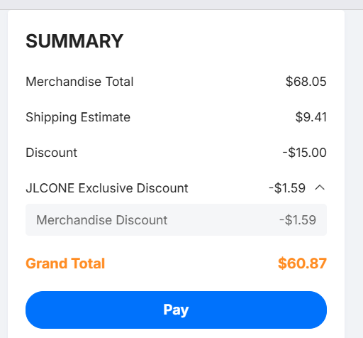
| Qty | Value | Footprint | References |
|---|---|---|---|
| 9 | SK6812_C5142047 | easyeda2kicad:LED-SMD_4P-L3.5-W2.8-BR-1 | LED1, LED2, LED3, LED4, LED5, LED6, LED7, LED8, LED9 |
| 8 | 2.2uF | easyeda2kicad:C0402 | C5, C6, C9, C10, C11, C12, C13, C14 |
| 5 | 0.1uF | easyeda2kicad:C0402 | C1, C2, C3, C15, C16 |
| 4 | 4.7k | easyeda2kicad:R0402 | R5, R6, R7, R8 |
| 3 | 10k | easyeda2kicad:R0402 | R1, R2, R3 |
| 3 | LOGO | LOGO | G***, G***, G*** |
| 2 | 15uF | easyeda2kicad:C1210 | C7, C8 |
| 2 | 1uF | easyeda2kicad:C0402 | C17, C18 |
| 1 | 200k | easyeda2kicad:R0402 | R4 |
| 1 | 330 | easyeda2kicad:R0402 | R9 |
| 1 | 4.7uF | easyeda2kicad:C0603 | C4 |
| 1 | 74AHCT1G125GV | easyeda2kicad:SOT-23-5_L3.0-W1.7-P0.95-LS2.8-BL | U7 |
| 1 | CS43131-CNZR | easyeda2kicad:TQFN-40_L5.0-W5.0-P0.40-TL-EP3.5 | U1 |
| 1 | PCA9306DCUR | easyeda2kicad:SSOP-8_L2.0-W2.3-P0.50-LS3.1-BR | U3 |
| 1 | PJ-327A 5JJ | easyeda2kicad:AUDIO-SMD_PJ-327A5JJ | CN1 |
| 1 | SN74AXC4T245PWR | easyeda2kicad:TSSOP-16_L5.0-W4.4-P0.65-LS6.4-BL | U4 |
| 1 | XIAO-RP2350-DIP | Seeed Studio XIAO Series Library:XIAO-RP2350-DIP | U2 |
| 1 | XTPS7A2018 | easyeda2kicad:SOT-23-5_L3.0-W1.7-P0.95-LS2.8-BL | U5 |

youheng7185/xmos_xu316_cs43131_usb_aud
uac 2.0 on xmos xu316 with cs43131 audio codec


sneakylizard123-4/MP3player
Why the STM32H743: it has the RAM to buffer audio enough peripherals that almost every feature ended up on its own bus and 480MHz means I never have to care about optimization.

lucg/seeed-xiao-esp32s3-expander
An expansion board for the Seeed Studio XIAO ESP32-S3 (Plus) using the B2B connector

M-Skut/kl05z-devboard-demo
Firmware + hardware for KL05Z Development Board Add-on

arkandas/rp2350-macropad
RP2350A 3x3 mechanical macropad with a browser-programmable keymap and an on-board status LCD

dermatoid-collab/EVC_FW
Progetto hardware e firmware del sistema di controllo di un ascensore domestico a trazione (TTF) di LiftingItalia s.r.l. Quattro schede basate su STM32F446, collegate in CAN; il motore è comandato da un VFD.

xeno3dev/LumaDD
LumaDD is a Custom Display Driver Board designed around a display I got off Alibaba, with Touch Support. It features HDMI -> MIPI DSI video signal conversion, USB-C for Touch Signals + Power, as well as an onboard…
It measures 35.1 × 58.3 mm and has 4 copper layers, 1.6 mm thick.
46 parts, built around the 74AHCT1G125GV, CS43131-CNZR, PCA9306DCUR and XTPS7A2018-XC. The full list of its parts is on this page, with links to each part's symbol and footprint where PCBKit's library has them.
From the Person-0/PicoDAC repository on GitHub, at the commit this page was made from: the board is hardware/PicoDAC/PicoDAC.kicad_pcb and its schematic hardware/PicoDAC/PicoDAC.kicad_sch. PCBKit opens the board in the browser, with nothing to install.
Its repository states no licence, so its author keeps all rights: ask Person-0 before reusing the design.