2 layers50 × 86 mm
KiCad RaspberryPiPico
ngc6589/Si4735_Radio_RaspberryPiPico
Raspberry Pi Pico とタッチ液晶で Si4735 DSP ラジオを作成しました
27 parts9MIT

 ngc6589/Si4735_Radio_RaspberryPiPico9
Raspberry Pi Pico とタッチ液晶で Si4735 DSP ラジオを作成しました
KiCad Si4735 is an open-source printed circuit board by ngc6589, from the ngc6589/Si4735_Radio_RaspberryPiPico repository on GitHub, published under the MIT licence. It is a 4-layer board of 50 × 86 mm with 80 parts on 63 nets, routed with 422 tracks and 57 vias.
It is built around the SI4735-D60-GU, 1N4148W and 1N5819HW. Its parts include 23 capacitors, 20 resistors, 7 diodes, 6 connectors and 3 ICs.


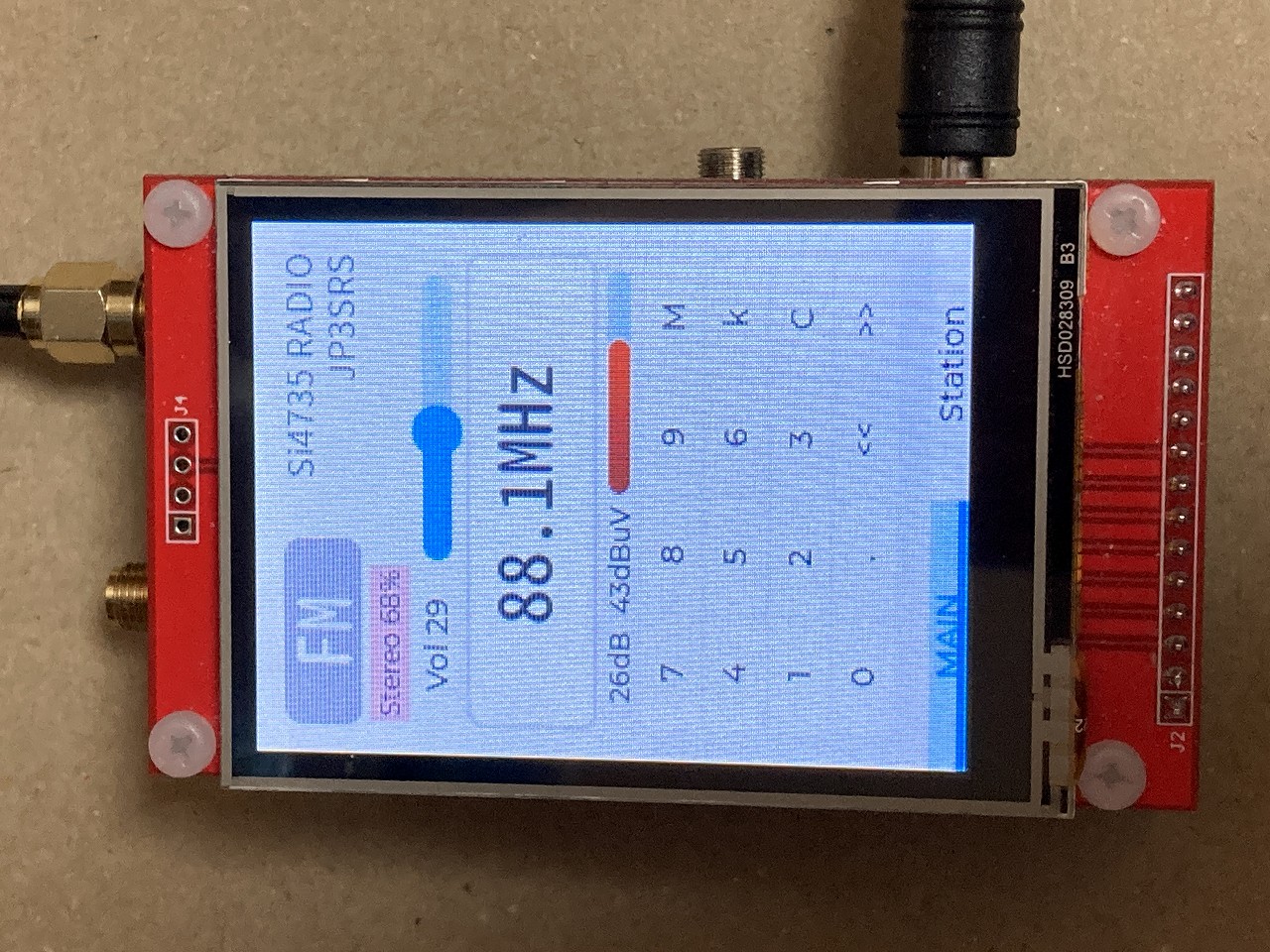
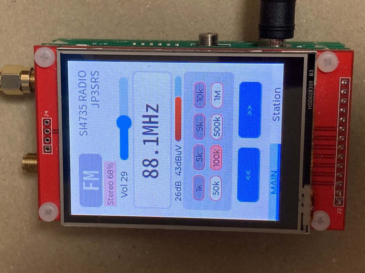
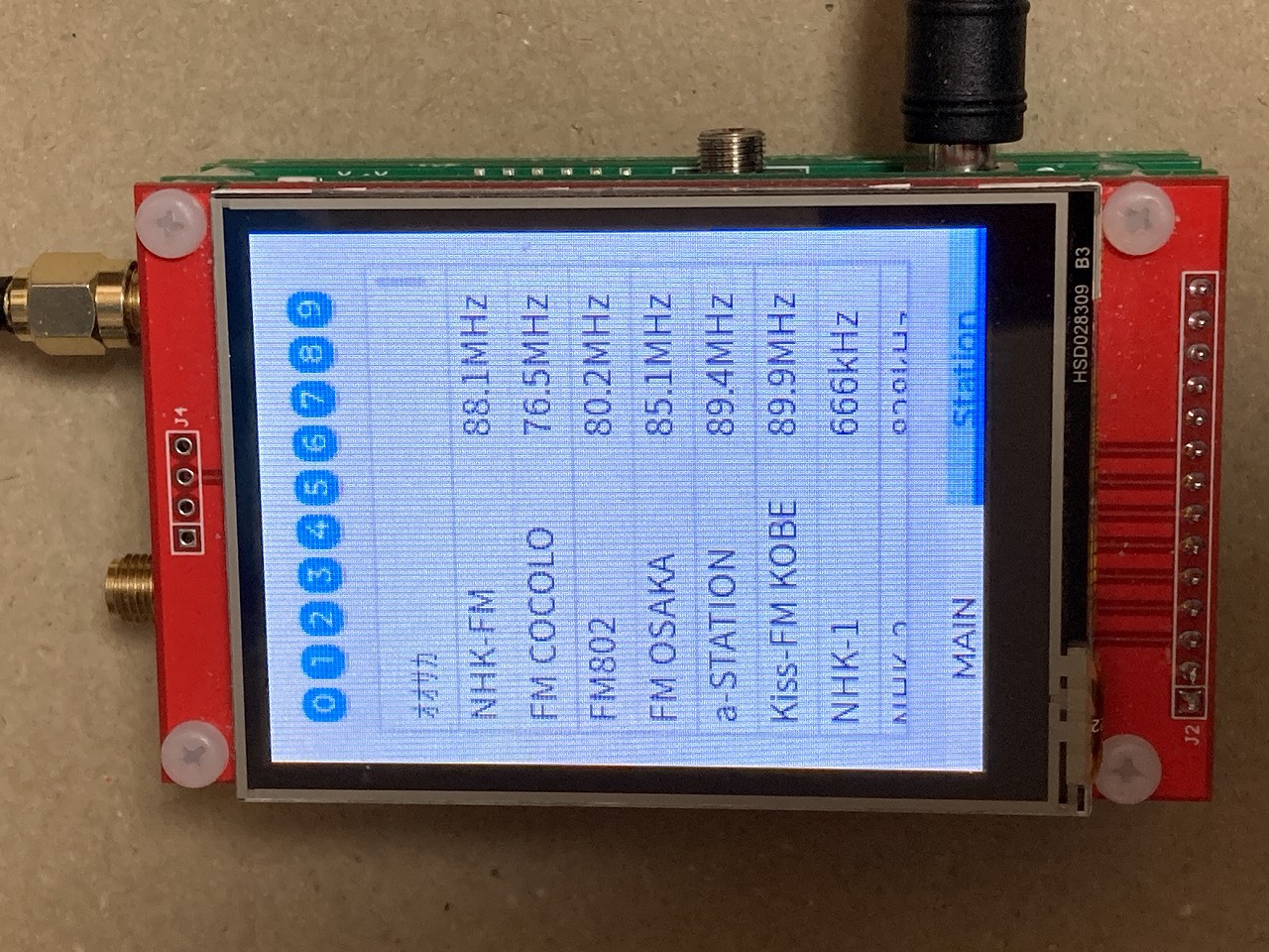
Raspberry Pi Pico と ILI9341 タッチ液晶を使用し、Si4735 DSP ラジオチップを動かすラジオを製作しました。写真のように周波数を入力してチューニングする画面、ステップ周波数のUP/DOWNチューニング、選局リストからチューニングのモードを備えています。 このラジオの Raspberry Pi Pico のファームウエアは micropython に lvgl グラフィックライブラリをバインドした lv_micropython というものを使用しています。この lv_micropython は https://github.com/lvgl/lv_micropython にて公開されています。これにフリーフォントなどを加えたカスタマイズ版のファームウエアを作成しています。 このファームウエアに micropython で記述したラジオアプリケーションを動かして上記機能を実現しました。
現在 MicroPython は 1.20 がリリースされましたが、lv_micropython はまだ 1.19 なので、当ラジオのファームウエアの MicroPython は 1.19 です。
| フォルダ | 用途 |
|---|---|
| Application | Raspberry Pi Pico の Micro Python ローカルストレージに格納するファイルです |
| Doc | 回路図の pdf と部品表のエクセルファイル |
| KiCad_RaspberryPiPico | Raspberry Pi Pico の KiCad ファイルです。ガーバーは pico-20230412 フォルダに入っています |
| KiCad_SP | マイクロスピーカーを着ける KiCad ファイルです。ガーバーは SP-20230412 フォルダに入っています |
| KiCad_Si4735 | Si4735 の KiCad ファイルです。ガーバーは RD-20230412 フォルダに入っています。この基板は4層です。 |
| lv_micropython_Firmware | Raspberry Pi Pico の Flash に書き込む lv_micropython のファームウエアです。firmware.uf2 を書き込んで下さい。 |
KiCad ファイルはバージョンは 7.0.2 で作成しました。
Raspberry Pi Pico の RAMが 264kB なので画面にグラフィックスウイジェットをたくさん出すとハングアップします。特に選局リストは放送局分のオブジェクトを内部で作成するので、選局リストをいじくりまわしていると固まることが多いです。選局して放置している分には特にハングアップは発生しません。 画面が動かなくなった場合が液晶基板右上に白いタクトスイッチが付いてます。これは RESET スイッチです。これを押して再起動してください。
今後 lvgl や micropython の新バージョンがリリースされても改善の見込みはありません。
Raspberry Pi Pico のUSB端子もしくはとDCジャックから給電します。同時挿しも問題ありません。DCジャックから給電する場合は 5V のスイッチング AC アダプタを使用してください。
トランス式 AC アダプタの場合は表示が 5V でも電源電圧が 5V 以上になっているため使用できません。ラジオのボードは壊れます。
周波数入力選局とステップチューニング画面は、画面上の余白をロングタップすると切り替わります。
選局リストチューニングは画面をスワイプもしくは画面下部の Station を押すと画面遷移します。戻るときは画面下部の MAIN を押すか画面スワイプで戻ります。
選局リスト画面上部に 0 ~ 9 のボタンがあります。ボタンをクリックすると micropython 内部ファイルシステムに格納してある [0-9].txt のファイルをリードして画面に表示します。
選局したい局の行をクリックするとその放送局にチューニングします。
周波数入力する時は「C」ボタンを押して、周波数表示が消えた状態で数字を入れて「k」か「M」ボタンをクリックして選局します。 入力途中で「C」を押すと元の周波数表示に戻ります。 「<<」「>>」はシークチューニングです。シーク後放送局が見つかるとシーク動作は停止します。
周波数表示の下に選択可能な周波数ステップボタンが表示されています。画面下部の「<<」「>>」1回クリックすると指定されたステップでチューニングします。長押しで連続ステップチューニング動作をします。
LW/MW/SW 受信時は SMA コネクタの後に 3SK291 を使用した1石高周波増幅回路を搭載しています。増幅率は左側面アンテナコネクタ近くにボリウムを設けています。このボリウムを回して放送の聞こえ具合を調整してください。左に回し切ると1石増幅器は停止し、放送は聞こえなくなります。右に回し切るとお住まいの電波環境にもよりますが複数の局が混信して聞こえることがあります。
正面から見て左が LW/MW/SW 用で右が FM 放送用のアンテナ端子です。アンテナ端子の形状は SMA タイプです。
2023年6月21日以前に購入された方は、I2S 出力ピンヘッダ横のダンピング抵抗 R1, R2, R3 を 100Ωに変えていただくことでビットクロックなどの波形が安定します。
| 端子名 | 備考 |
|---|---|
| BCLK | ビットクロック |
| DATA | データ |
| LRCK | LRクロック |
| GND | グランド |
| NC | 未接続 |
| VCC | 5V出力 3.3vではありません |
I2S 出力するときは、プログラムのラジオチップ初期化のコマンドを I2S 出力対応にする必要があります。
# Generate 48k I2S clock
# uncomment I2S OUTPUT
# @rp2.asm_pio(
#     sideset_init=(rp2.PIO.OUT_HIGH, rp2.PIO.OUT_HIGH)
# )
# def gen48k():
#     set(x, 30)       .side(0b00) [1]
#     nop()            .side(0b01) [1]
#     label("L01")
#     nop()            .side(0b00) [1]
#     jmp(x_dec, "L01").side(0b01) [1]
#     set(x, 30)       .side(0b10) [1]
#     nop()            .side(0b11) [1]
#     label("R01")
#     nop()            .side(0b10) [1]
#     jmp(x_dec, "R01").side(0b11) [1]
#
# sm0 = rp2.StateMachine(
#     0,
#     gen48k,
#     freq=12_288_000,
#     sideset_base=machine.Pin(4)
# )
# sm0.active(1)
のコメントを外します。 また、
    def FMPOWER_UP(self):
        self.i2c.writeto(self.addr, bytes([0x01, 0x00, 0x05]))  # analog Out
#         self.i2c.writeto(self.addr, bytes([0x01, 0x00, 0xB0]))   # I2S
        self.waitCTS()
        time.sleep(0.5)
        self.setProperty(bytes([0xFF, 0x00, 0x00, 0x00]))          # Turn off Debug Mode
# self.setProperty(bytes([0x01, 0x04, 0xBB, 0x80])) # I2s sample rate def AMPOWER_UP(self):
self.i2c.writeto(self.addr, bytes([0x01, 0x01, 0x05])) # analog out
# self.i2c.writeto(self.addr, bytes([0x01, 0x01, 0xB0])) # I2S
self.waitCTS()
time.sleep(0.5)
self.setProperty(bytes([0xFF, 0x00, 0x00, 0x00])) # Turn off Debug Mode
# self.setProperty(bytes([0x01, 0x04, 0xBB, 0x80])) # I2S sample rateの # analog out の行をコメントアウトして i2s のコメントを外すと I2S 出力になります。
デフォルトは 16bit/48k になります。
今回、ラジオのアプリケーション作成には Thonny Python IDE for beginners
で、公開されている IDE を使用しています。 プログラムの修正などしてみる場合はこれをインストールして Si4735Radio の USB 接続すれば lv_micropython の REPL が使えるようになります。
ローカルのファイルを lv_micropython のファイルシステムにコピーしたりその逆も可。ファイルの修正も可能です。
液晶基板上側両再度に白いタクトスイッチが左右2個付いています。右がリセット・左がBOOTです。
「左BOOT」「右RESET」 両方押す
「右RESET」 離す
「左BOOT」 離す
この後 Raspberry Pi Pico は USB メモリモードになってホスト側PCのファイルに RPI PICO のドライブが使えるようになります。ここに .uf2 ファイルのドラッグ・ドロップ(コピーペースト)すればファームウエアの更新が可能です。
| Qty | Value | Footprint | References |
|---|---|---|---|
| 6 | 1N4148W | Diode_SMD:D_SOD-123 | D2, D3, D4, D5, D6, D7 |
| 5 | 10k | Resistor_SMD:R_0603_1608Metric_Pad0.98x0.95mm_HandSolder | R10, R14, R15, R19, R20 |
| 5 | 4.7uF/6.3V | _localFootprint:YFF18PC | EMI1, EMI2, EMI3, EMI4, EMI5 |
| 4 | 1uF | Capacitor_SMD:C_0603_1608Metric_Pad1.08x0.95mm_HandSolder | C14, C18, C20, C22 |
| 4 | MountingHole | _localFootprint:MountingHole_3.2mm_M3 | H1, H2, H3, H4 |
| 3 | 0.1uF | Capacitor_SMD:C_0603_1608Metric_Pad1.08x0.95mm_HandSolder | C2, C12, C16 |
| 3 | 100k | Resistor_SMD:R_0603_1608Metric_Pad0.98x0.95mm_HandSolder | R8, R16, R17 |
| 3 | 10p | Capacitor_SMD:C_0603_1608Metric_Pad1.08x0.95mm_HandSolder | C11, C15, C23 |
| 2 | 0.01uF | Capacitor_SMD:C_0603_1608Metric_Pad1.08x0.95mm_HandSolder | C4, C6 |
| 2 | 12pF | Capacitor_SMD:C_0603_1608Metric_Pad1.08x0.95mm_HandSolder | C8, C9 |
| 2 | 1k | Resistor_SMD:R_0603_1608Metric_Pad0.98x0.95mm_HandSolder | R12, R13 |
| 2 | 2k | Resistor_SMD:R_0603_1608Metric_Pad0.98x0.95mm_HandSolder | R2, R3 |
| 2 | 330uF/6.3V | Capacitor_THT:CP_Radial_D8.0mm_P2.50mm | C17, C21 |
| 2 | 33k | Resistor_SMD:R_0603_1608Metric_Pad0.98x0.95mm_HandSolder | R11, R18 |
| 2 | 47uF | Capacitor_SMD:C_1210_3225Metric_Pad1.33x2.70mm_HandSolder | C10, C13 |
| 2 | XTAL | Jumper:SolderJumper-2_P1.3mm_Open_Pad1.0x1.5mm | JP3, JP4 |
| 1 | 0.022uF | Capacitor_SMD:C_0603_1608Metric_Pad1.08x0.95mm_HandSolder | C3 |
| 1 | 0.47uF | Capacitor_SMD:C_0603_1608Metric_Pad1.08x0.95mm_HandSolder | C5 |
| 1 | 10 | Resistor_SMD:R_0603_1608Metric_Pad0.98x0.95mm_HandSolder | R4 |
| 1 | 1000pF | Capacitor_SMD:C_0603_1608Metric_Pad1.08x0.95mm_HandSolder | C7 |
| 1 | 100uF/25V | Capacitor_SMD:CP_Elec_6.3x7.7 | C1 |
| 1 | 10k | _localFootprint:3306W | RV2 |
| 1 | 10k | _localFootprint:RV100F | RV1 |
| 1 | 1N5819HW | Diode_SMD:D_SOD-123 | D1 |
| 1 | 2.2uF | Capacitor_SMD:C_0603_1608Metric_Pad1.08x0.95mm_HandSolder | C19 |
| 1 | 22k | Resistor_SMD:R_0603_1608Metric_Pad0.98x0.95mm_HandSolder | R5 |
| 1 | 270nH | _localFootprint:L2 | L2 |
| 1 | 32.768kHz | _localFootprint:FC-135 | Y1 |
| 1 | 39k | Resistor_SMD:R_0603_1608Metric_Pad0.98x0.95mm_HandSolder | R7 |
| 1 | 3SK291 | _localFootprint:SOT-143_Handsoldering | Q1 |
| 1 | 47k | Resistor_SMD:R_0603_1608Metric_Pad0.98x0.95mm_HandSolder | R9 |
| 1 | 5V | _localFootprint:MJ-179PH | J2 |
| 1 | 620 | Resistor_SMD:R_0603_1608Metric_Pad0.98x0.95mm_HandSolder | R1 |
| 1 | 91k | Resistor_SMD:R_0603_1608Metric_Pad0.98x0.95mm_HandSolder | R6 |
| 1 | AM/SW | _localFootprint:SMA-J-P-H-ST-EM1 | J4 |
| 1 | BCLK | Jumper:SolderJumper-2_P1.3mm_Open_Pad1.0x1.5mm | JP1 |
| 1 | Conn_02x08_Odd_Even | Connector_PinHeader_2.54mm:PinHeader_2x08_P2.54mm_Vertical | J3 |
| 1 | FM | _localFootprint:SMA-J-P-H-ST-EM1 | J5 |
| 1 | FT37-77 12T | _localFootprint:FT37 | L1 |
| 1 | I2SOUT | Connector_PinHeader_2.54mm:PinHeader_1x06_P2.54mm_Horizontal | J1 |
| 1 | LOGO | _localFootprint:centerPlus | G*** |
| 1 | Phone OUT | _localFootprint:MJ-352W-0 | J6 |
| 1 | RCLK | Jumper:SolderJumper-2_P1.3mm_Open_Pad1.0x1.5mm | JP2 |
| 1 | Si4735-D60-GU | _localFootprint:SSOP-24_3.9x8.7mm_P0.635mm | U1 |
| 1 | Speaker | Connector_PinHeader_2.54mm:PinHeader_1x02_P2.54mm_Horizontal | LS1 |
| 1 | TPA6111A2DR | Package_SO:SO-8_3.9x4.9mm_P1.27mm | U3 |
| 1 | TPA711DR | Package_SO:SO-8_3.9x4.9mm_P1.27mm | U2 |
ngc6589/Si4735_Radio_RaspberryPiPico
Raspberry Pi Pico とタッチ液晶で Si4735 DSP ラジオを作成しました

ngc6589/Si4735_Radio_RaspberryPiPico
Raspberry Pi Pico とタッチ液晶で Si4735 DSP ラジオを作成しました

LadyRoninEngineer/Si473x
Data Supporting development of Si473x series radios


EthicalEarth/Radio_SI4735_v1.0_stable
Stable final release of DSP Radio based on si4735 chip.

Hasnat4763/Akash-Chowa-DX
Akash Chowa DX is a SW/MW/LW receiver designed based on the Si4735 Radio receiver IC paired with the RP2040 Zero Dev board.

SREERAJSVT/SiSeriesRadio
This project details the design and development of a Si4732/Si4735 based radio receiver utilizing a Raspberry Pi Pico for control and a custom-designed PCB


It measures 50 × 86 mm and has 4 copper layers, 1.6 mm thick.
80 parts, built around the SI4735-D60-GU, 1N4148W and 1N5819HW. The full list of its parts is on this page, with links to each part's symbol and footprint where PCBKit's library has them.
From the ngc6589/Si4735_Radio_RaspberryPiPico repository on GitHub, at the commit this page was made from: the board is KiCad_Si4735/KiCad-Si4735.kicad_pcb and its schematic KiCad_RaspberryPiPico/KiCad.kicad_sch. PCBKit opens the board in the browser, with nothing to install.
Its repository publishes it under the MIT licence: you may reuse it on that licence's terms (keep the author's notice, and for a copyleft licence share your changes alike).