6 layers50 × 50 mm
MUSIC PLAYER
Ace6Rings/MUSIC-PLAYER
Why did I build something like this? Well, I am sick and tired of buying spotify premium every month. I looked for mp3 players online but nearly all of them have the same flaw(s).
96 partsMIT

 Hasnat4763/Akash-Chowa-DX1
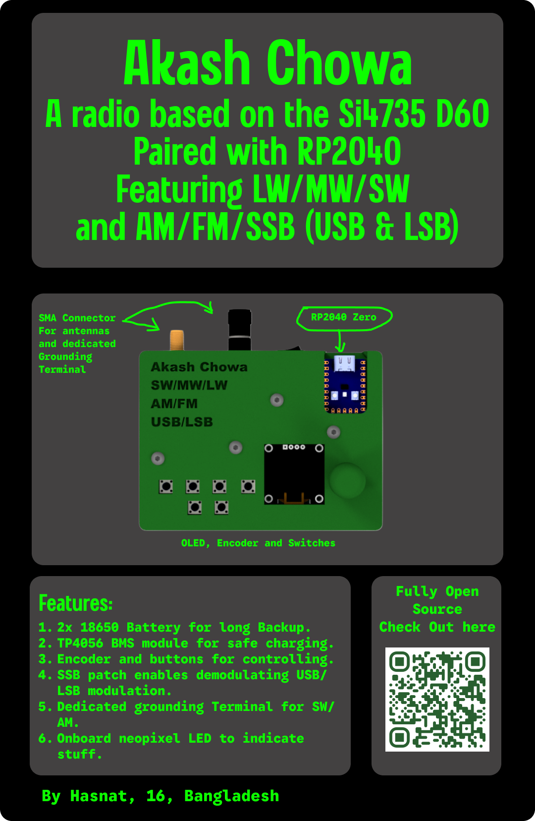
Akash Chowa DX is a SW/MW/LW receiver designed based on the Si4735 Radio receiver IC paired with the RP2040 Zero Dev board.
Akash Chowa DX is an open-source printed circuit board by Hasnat4763, from the Hasnat4763/Akash-Chowa-DX repository on GitHub, published under the MIT licence. It is a 4-layer board of 98.5 × 70.9 mm with 49 parts on 60 nets, routed with 301 tracks and 93 vias.
It is built around the PE4259-63, SI4735-D60-GU and TPA6132A2RTE, with the RP2040-ZERO and PRTR5V0U2X among its other parts. Its parts include 13 capacitors, 7 switches, 4 ICs, 4 connectors and 2 resistors. It belongs with the RP2040 boards of this library.


Akash Chowa DX is a SW/MW/LW receiver designed based on the Si4735 Radio receiver IC paired with the RP2040 Zero Dev board.
I had an affection towards Radios from childhood. I sometimes try to receive SW stations on my 5$ budget radio I had gotten from a local store. But It does not work that efficiently and I needed a better receiver. Also the radio I currently have can not demodulate SSB (Single Sideband) and RDS transmitted by modern FM stations. So I designed it to fulfill my own requirements. It also helped me learn new things like impedance control.
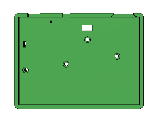
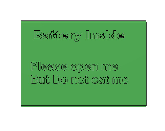
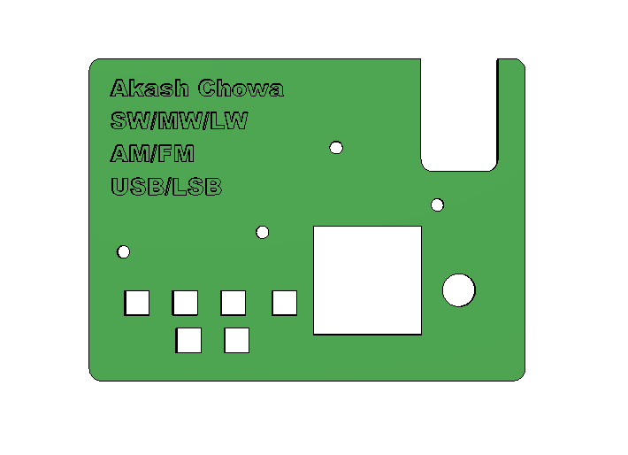
Here are some pictures of what I designed
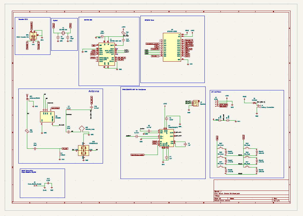
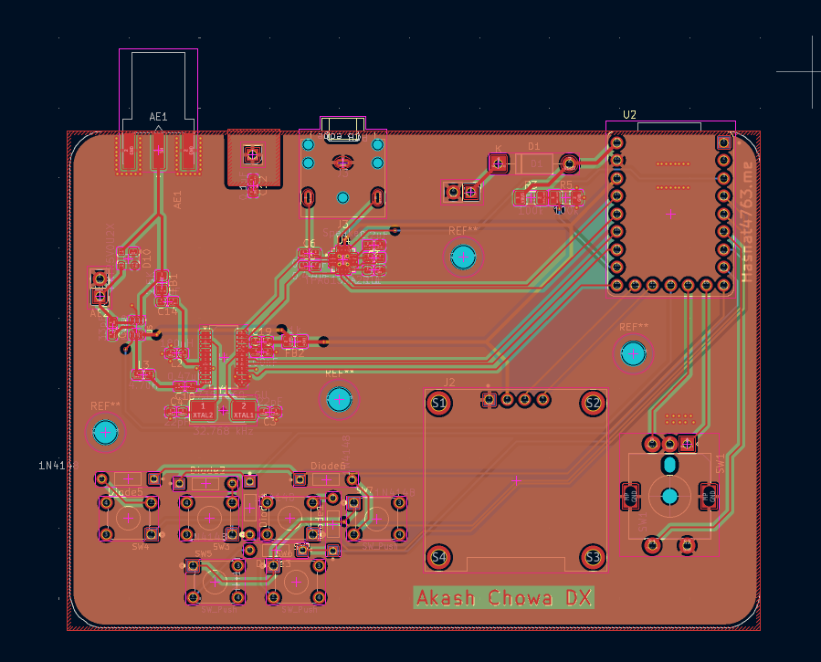
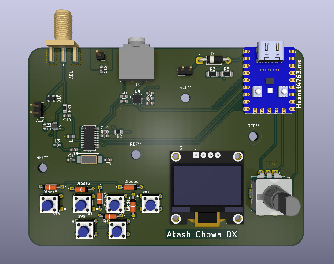
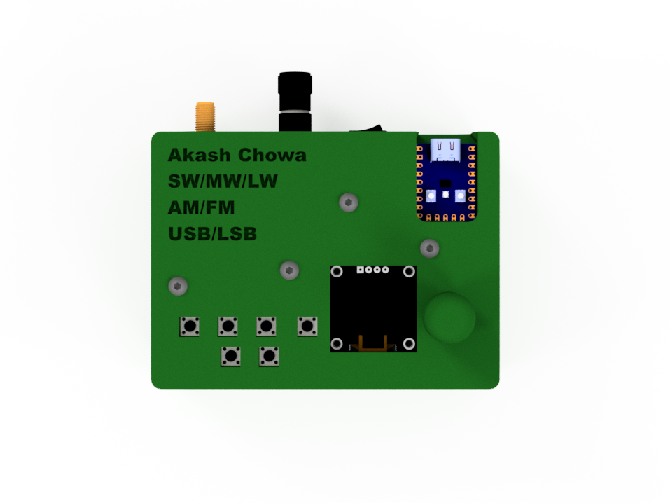
Base of the case
battery cover
top cover
| Item | Quantity | Price | Link |
|---|---|---|---|
| Waveshare RP2040 Zero | 1 | $5.86 | Link |
| 1N5819 Diode | 100 | $5.49 | Link |
| 1N4148 Diode | 100 | $4.43 | Link |
| SSD1306 OLED Display | 1 | $5.33 | Link |
| EC 11 Encoder with Push Button Half Handle 20MM Shaft | 5 | $6.31 | Link |
| Si4735 D60 GU | 1 | $8.06 | Link |
| PE4259 | 20 | $4.96 | Link |
| 32.768 kHz Crystal SMD | 10 | $5.01 | Link |
| 2.5K Ferrite Bead | 100 | $1.63 | Link |
| 1K Ferrite Bead | 100 | $1.70 | Link |
| 100uF, 10uF, 100nF, 22pF, 1uF, 0.47uF, 33pF, 18pF, 22nF Capacitor Pack | 720 | $6.21 | Link |
| 100 ohm Resistor 1206 | 100 | $1.61 | Link |
| 20k ohm Resistor 1206 | 100 | $1.61 | Link |
| 100k ohm Resistor 1206 | 100 | $1.61 | Link |
| SMA connector Edge Mount | 5 | $5.32 | Link |
| 180nH Inductor 0603 | 100 | $1.33 | Link |
| 4.7uH Inductor 0603 | 100 | $1.33 | Link |
| Tactile Switches Push buttons | 20 | $4.12 | Link |
| PRTR5V0U2X ESD protection Diode | 10 | $4.66 | Link |
| TPA6132A2RTE Headphone Amplifier | 5 | $3.35 | Link |
| 18650 Lithium Battery | 2 | BDT 510 (~$4.16) | Link |
| TP4056 BMS | 1 | $4.02 | Link |
| Rocker Switch | 5 | $5.20 | Link |
| Binding Post | 5 | $6.00 | Link |
| Headphone Connector | 10 | $4.45 | Link |
| AM ferrite Antenna | 2 | $10.04 | Link |
| Whip SMA Antenna | 1 | $8.93 | Link |
| M3 Heat Set Inserts | 30 | $6.13 | Link |
| M3 Fasteners | 50 | $6.28 | Link |
| Top Case | 1 | Printing Legion | Link |
| Bottom Case | 1 | Printing Legion | Link |
| Battery Cover | 1 | Printing Legion | Link |
| PCB | 5 | $6.24 | Link |
For impedance control, while ordering from JLCPCB, select the JLC04161H-7628 layer stackup. Also better to import this to the Easyeda Pro and then order as that can get you a few extra discounts.
For ordering parts, you can find most components in LCSC but some components may not be available in LCSC so it needs to be bought from 3rd party stores like aliexpress/alibaba.
For the AM antenna its better to source it from an old broken radio, as its hard to find ferrite antennas online and those tend to be very expensive.
Also buy parts like the TP4056, binding post and 18650 batteries locally as on aliexpress they tend to be a lot more expensive.
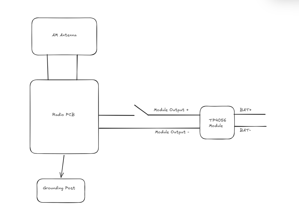
Batteries need to be connected in parralel as the tp4056 is a 1S BMS.
Connect the switch in series to the TP4056 output's positive terminal and the PCB's positive power input. PCB's negative and TP4056's negative also needs to be connected.
It should look something like this
You can use a 9:1 balun to connect a longwire antenna to the SMA connector.
For grounding you may be able to just lay the wire parallel to the ground for a few meters.
To flash the firmware, you first need to add the board to your arduino IDE.
After getting into the Arduino IDE, Go to Preference
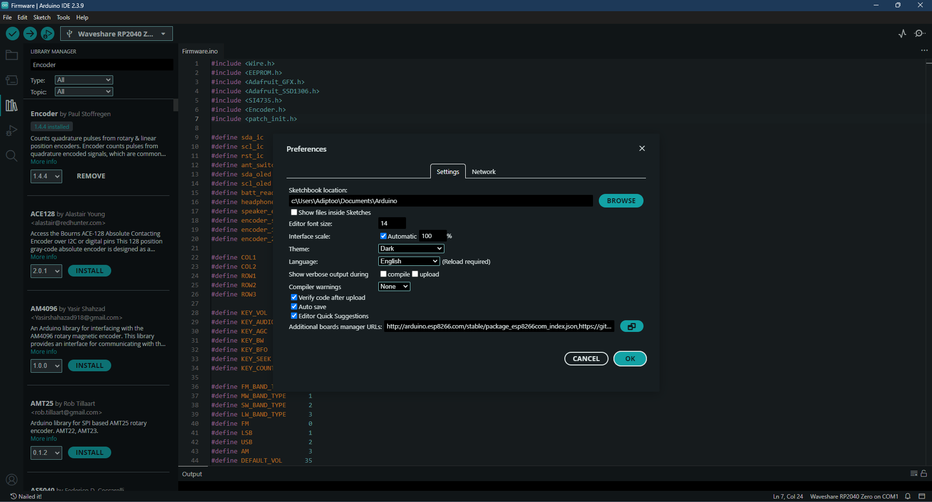
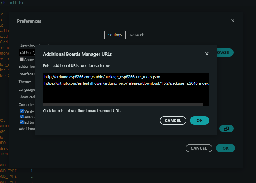
Now click on the additional board manager URL and add https://github.com/earlephilhower/arduino-pico/releases/download/4.5.2/package_rp2040_index.json
Now go to boards manager and search RP2040 and download this library
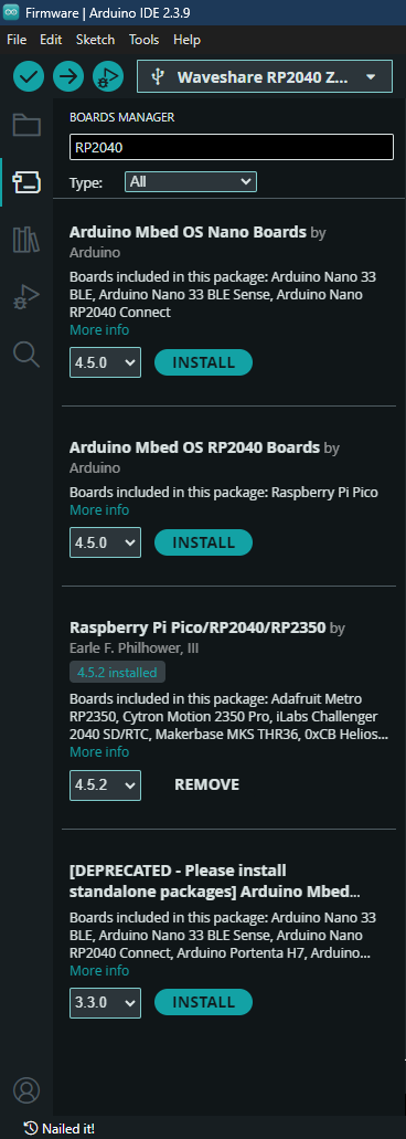
Now you can select the MCU as the waveshare RP2040 zero.
After that you need a few libraries Si4735 library Adafruit SSD1306 library Adafruit GFX library and the Rotary Encoder Library by Paul Stoffregen
Then you can flash the firmware.
For more details on the Si4735 follow the directions in Si4735 Arduino Library here.
| Qty | Value | Footprint | References |
|---|---|---|---|
| 6 | 1N4148 | 1N4148:DIOAD753W49L380D172B | Diode1, Diode2, Diode3, Diode4, Diode5, Diode6 |
| 6 | SW_Push | FSM8JH:SW_FSM8JH | SW2, SW3, SW4, SW5, SW6, SW7 |
| 3 | 0.47uF | Capacitor_SMD:C_0603_1608Metric_Pad1.08x0.95mm_HandSolder | C5, C6, C10 |
| 2 | 100k | Resistor_SMD:R_1206_3216Metric_Pad1.30x1.75mm_HandSolder | R3, R5 |
| 2 | 1uF | Capacitor_SMD:C_0603_1608Metric_Pad1.08x0.95mm_HandSolder | C2, C7 |
| 2 | 22pF | Capacitor_SMD:C_0603_1608Metric_Pad1.08x0.95mm_HandSolder | C3, C4 |
| 1 | 0.1uF | Capacitor_SMD:C_0603_1608Metric_Pad1.08x0.95mm_HandSolder | C12 |
| 1 | 100nF | Capacitor_SMD:C_0603_1608Metric_Pad1.08x0.95mm_HandSolder | C20 |
| 1 | 180nH | Inductor_SMD:L_0603_1608Metric_Pad1.05x0.95mm_HandSolder | L2 |
| 1 | 18pF | Capacitor_SMD:C_0603_1608Metric_Pad1.08x0.95mm_HandSolder | C14 |
| 1 | 1N5819 | Diode_THT:D_DO-41_SOD81_P10.16mm_Horizontal | D1 |
| 1 | 1k | Resistor_SMD:R_0805_2012Metric_Pad1.20x1.40mm_HandSolder | FB2 |
| 1 | 2.2uF | Capacitor_SMD:C_0603_1608Metric_Pad1.08x0.95mm_HandSolder | C1 |
| 1 | 2.5K | Resistor_SMD:R_0805_2012Metric_Pad1.20x1.40mm_HandSolder | FB1 |
| 1 | 22nF | Capacitor_SMD:C_0603_1608Metric_Pad1.08x0.95mm_HandSolder | C19 |
| 1 | 32.768 kHz | Crystal:Crystal_SMD_0603-2Pin_6.0x3.5mm_HandSoldering | Y1 |
| 1 | 33pF | Capacitor_SMD:C_0603_1608Metric_Pad1.08x0.95mm_HandSolder | C11 |
| 1 | 4.7uH | Inductor_SMD:L_0603_1608Metric_Pad1.05x0.95mm_HandSolder | L3 |
| 1 | Antenna_Loop | Connector_PinHeader_2.54mm:PinHeader_1x02_P2.54mm_Vertical | AE2 |
| 1 | Antenna_Shield | Connector_Coaxial:SMA_Amphenol_132289_EdgeMount | AE1 |
| 1 | Battery Connection | Connector_PinHeader_2.54mm:PinHeader_1x02_P2.54mm_Vertical | J4 |
| 1 | Conn_01x01_Socket | Connector_PinHeader_2.54mm:PinHeader_1x01_P2.54mm_Vertical | J5 |
| 1 | EC11 Encoder/SW | Rotary_Encoder:RotaryEncoder_Alps_EC11E-Switch_Vertical_H20mm_MountingHoles | SW1 |
| 1 | OLED | DM-OLED096-636:MODULE_DM-OLED096-636 | J2 |
| 1 | PE4259 | PE4259:SOT65P215X110-6N | U5 |
| 1 | PRTR5V0U2X | Package_TO_SOT_SMD:SOT-143 | D10 |
| 1 | RP2040-ZERO | RP2040-ZERO:MODULE_RP2040-ZERO | U2 |
| 1 | Si4735-D60-GU | Package_SO:SSOP-24_3.9x8.7mm_P0.635mm | U1 |
| 1 | Speaker | Connector_Audio:Jack_3.5mm_CUI_SJ1-3523N_Horizontal | J3 |
| 1 | TPA6132A2RTE | Package_DFN_QFN:WQFN-16-1EP_3x3mm_P0.5mm_EP1.6x1.6mm_ThermalVias | U4 |
The 45 most common of 49 parts.
Ace6Rings/MUSIC-PLAYER
Why did I build something like this? Well, I am sick and tired of buying spotify premium every month. I looked for mp3 players online but nearly all of them have the same flaw(s).

Horizon-Avionics/Horizon-H1
Building a fully open-source flight computer for amateur rocketry!

Stab-Rabbit-coding/Serenity-UAV
A functional, security conscious, Unmanned Aerial Vehicle based on the Firefly Class spacecraft Serenity from the 2002 show..

knivier/SkyCell
The telecommunications solution on a balloon...for broke people alike.

LadyRoninEngineer/Si473x
Data Supporting development of Si473x series radios


ngc6589/Si4735_Radio_RaspberryPiPico
Raspberry Pi Pico とタッチ液晶で Si4735 DSP ラジオを作成しました

It measures 98.5 × 70.9 mm and has 4 copper layers, 1.6 mm thick.
49 parts, built around the PE4259-63, SI4735-D60-GU, TPA6132A2RTE and RP2040-ZERO. The full list of its parts is on this page, with links to each part's symbol and footprint where PCBKit's library has them.
From the Hasnat4763/Akash-Chowa-DX repository on GitHub, at the commit this page was made from: the board is PCB/Akash Chowa DX.kicad_pcb and its schematic PCB/Akash Chowa DX.kicad_sch. PCBKit opens the board in the browser, with nothing to install.
Its repository publishes it under the MIT licence: you may reuse it on that licence's terms (keep the author's notice, and for a copyleft licence share your changes alike).