2 layers208 × 110 mm

 skiselev/easy_z80180
An easy to build Zilog Z80 based single board computer
Easy z80 is an open-source printed circuit board by skiselev, from the skiselev/easy_z80 repository on GitHub, published under the GPL-3.0 licence. It is a 2-layer board of 99.9 × 99.9 mm with 61 parts on 126 nets, routed with 1,845 tracks and 87 vias.
It is built around the MAX232ACSE+, 74HC670P-E and 74HC74D, with the MAX693CPE+ among its other parts. Its parts include 23 capacitors, 12 ICs, 7 connectors, 5 resistors and 1 diode. It belongs with the retro computing and games and computers and single-board computers boards and the FPGA and CPLD boards of this library.


An easy to build Zilog Z80 based single board computer
My son Max asked me what it takes to build a computer, and whether or not he can design and build one himself. This project is our attempt to design and build a simple, easy to understand, yet capable single board computer. It reuses the same memory paging mechanism I've implemented in Zeta SBC V2. It uses the Zilog Z80 SIO/O, Z80 CTC peripheral ICs, and implements daisy chain mode 2 interrupt configuration.
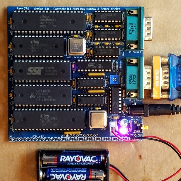
For the version 1.0 schematic, PCB layout, and bill of materials please refer to tag v1.0
Connect regulated +5V power supply to this connector.
| Pin | Signal Name | Description |
|---|---|---|
| Tip (the inner contact) | VCC | Positive terminal - +5V |
| Barrel / sleeve | GND | Negative terminal - ground |
| Pin | Signal Name | Description |
|---|---|---|
| 1 | DCD | Carrier Detect; Not used - Not connected on the SBC |
| 2 | RXA, RXB | Receive Data; Input to SBC |
| 3 | TXA, TXB | Transmit Data; Output from SBC |
| 4 | DTR | Data Terminal Ready; Not used - Not connected on the SBC |
| 5 | GND | Connected to the SBC GND signal |
| 6 | DSR | Data Set Ready; Not used - Not connected on the SBC |
| 7 | RTSA, RTSB | Request to Send; Output from SBC |
| 8 | CTSA, CTSB | Clear to Send; Input to SBC |
| 9 | RI | Ring Indicator; Not used - Not connected on the SBC |
| Shield | DE9 Shield | Connected to the SBC GND signal |
Connect 3V battery for SRAM backup to this connector.
Important: If the SRAM battery backup is not desired, short J4 with a jumper. Do not leave this connector open.
| Pin | Signal Name | Description |
|---|---|---|
| 1 | VBAT | Positive terminal - +3V |
| 2 | GND | Negative terminal - ground |
| Pin | Signal Name | Description | Pin | Signal Name | Description |
|---|---|---|---|---|---|
| J5-1 | A15 | Address A15; Output | |||
| J5-2 | A14 | Address A14; Output | |||
| J5-3 | A13 | Address A13; Output | |||
| J5-4 | A12 | Address A12; Output | |||
| J5-5 | A11 | Address A11; Output | |||
| J5-6 | A10 | Address A10; Output | |||
| J5-7 | A9 | Address A9; Output | |||
| J5-8 | A8 | Address A8; Output | |||
| J5-9 | A7 | Address A7; Output | |||
| J5-10 | A6 | Address A6; Output | |||
| J5-11 | A5 | Address A5; Output | |||
| J5-12 | A4 | Address A4; Output | |||
| J5-13 | A3 | Address A3; Output | |||
| J5-14 | A2 | Address A2; Output | |||
| J5-15 | A1 | Address A1; Output | |||
| J5-16 | A0 | Address A0; Output | |||
| J5-17 | GND | Ground | J6-1 | GND | Ground |
| J5-18 | VCC | Power Supply - +5V | J6-2 | VCC | Power Supply - +5V |
| J5-19 | /M1 | Machine Cycle One; Output | J6-3 | /RFSH | DRAM refresh; Output |
| J5-20 | /RESET | Reset; Output | J6-4 | N/C | Not connected |
| J5-21 | CPU_CLK | CPU Clock; Output | J6-5 | UART_CLK | UART Clock (1.8432 MHz); Output |
| J5-22 | /INT | Interrupt; Input | J6-6 | /BUSACK | DMA Bus Acknowledge; Output |
| J5-23 | /MREQ | Memory Request; Output | J6-7 | /HALT | Halt; Output |
| J5-24 | /WR | Write Request; Output | J6-8 | /BUSREQ | DMA Bus Request; Input |
| J5-25 | /RD | Read Request; Output | J6-9 | /WAIT | Wait; Input |
| J5-26 | /IORQ | Input/Output Request; Output | J6-10 | /NMI | Non-maskable Interrupt; Input |
| J5-27 | D0 | Data D0; Input/Output | |||
| J5-28 | D1 | Data D1; Input/Output | |||
| J5-29 | D2 | Data D2; Input/Output | |||
| J5-30 | D3 | Data D3; Input/Output | |||
| J5-31 | D4 | Data D4; Input/Output | |||
| J5-32 | D5 | Data D5; Input/Output | |||
| J5-33 | D6 | Data D6; Input/Output | |||
| J5-34 | D7 | Data D7; Input/Output | |||
| J5-35 | TXDA | Channel A, Transmit Data; Output | J7-1 | TXDB | Channel B, Transmit Data; Output |
| J5-36 | RXDA | Channel A, Receive Data; Input | J7-2 | RXDB | Channel B, Receive Data; Input |
| J5-37 | USR1 | User Pin 1, Not connected | J7-3 | USR5 | User Pin 5, Not connected |
| J5-38 | IEI | Interrupt Enable Input | J7-4 | USR6 | User Pin 6, Not connected |
| J5-39 | IEO | Interrupt Enable Output | J7-5 | USR7 | User Pin 7, Not connected |
| Position | Description |
|---|---|
| 1-2 (default) | 1.8432 MHz (115200 bps if using x16 mode) |
| 2-3 | Programmable using CTC channel 0 |
| Position | Description |
|---|---|
| 1-2 (default) | 1.8432 MHz (115200 bps if using x16 mode) |
| 2-3 | Programmable using CTC channel 1 |
Easy Z80 project on Mouser.com - View and order all components except of the PCB.
Easy Z80 project on OSH Park - View and order the PCB.
| Component type | Reference | Description | Quantity | Possible sources and notes |
|---|---|---|---|---|
| PCB | Easy Z80 PCB - Version 1.1 | 1 | Refer to the RetroBrew Computers Board Inventory page for ordering information, or order from a PCB manufacturer of your choice using provided Gerber or KiCad files | |
| Integrated Circuit | U1 | Z80 CPU, CMOS, 40 pin DIP - Z84C00xxPEG | 1 | Mouser 692-Z84C0010PEG |
| Integrated Circuit | U2 | Z80 CTC, CMOS, 28 pin DIP - Z84C30xxPEG | 1 | Mouser 692-Z84C3010PEG |
| Integrated Circuit | U3 | Z80 SIO/0, CMOS, 40 pin DIP - Z84C40xxPEG | 1 | Mouser 692-Z84C4010PEG |
| Integrated Circuit | U4 | 512 KiB SRAM, 32 pin DIP - AS6C4008 | 1 | Mouser 913-AS6C4008-55PCN |
| Integrated Circuit | U5 | 512 KiB Flash ROM, 32 pin DIP - SST39SF040 | 1 | Mouser 804-39SF0407CPHE |
| Integrated Circuit | U6 | Microprocessor Supervisory Circuit - MAX693 | 1 | Mouser 584-ADM693ANZ; Possible alternatives: MAX693, LTC693, ADM691, MAX691, LTC691, ADM695, MAX695, LTC965, LTC1235 |
| Integrated Circuit | U7, U8 | Dual RS-232 Driver/Receiver - MAX232A | 2 | Mouser 595-TRS202EIN |
| Integrated Circuit | U9 | Simple Programmable Logic Device - ATF16V8B | 1 | Mouser 556-AF16V8B15PU |
| Integrated Circuit | U10, U11 | 4-by-4 Register File - 74HC670 | 2 | Mouser 595-CD74HC670E |
| Integrated Circuit | U12 | Dual Flip Flop - 74HC74 | 1 | Mouser 595-SN74HC74N |
| Oscillator | QG1 | 10 MHz, CMOS oscillator, Half Can | 1 | Mouser 774-MXO45HS-3C-10.0 |
| Oscillator | QG2 | 1.8432 MHz, CMOS oscillator, Half Can | 1 | Mouser 774-MXO45HS-3C-1.8 |
| LED | D1 | 3 mm, green LED indicator | 1 | Mouser 859-LTL-4231N |
| Tactile Button | SW1 | 6 mm tactile button, right angle | 1 | Mouser 653-B3F-3152 |
| Connector | J1 | DC Power Jack, 2mm | 1 | Mouser 806-KLDX-0202-A |
| Connector | J2, J3 | Sub-D DE9M, Right Angle, PCB mount | 2 | Mouser 806-K22X-E9P-N-99 |
| Connector | J4 | 2 Pin Header with Friction Lock | 1 | Mouser 571-6404562 |
| Pin Header | J5 - J7 | 40x2 Pin Header, 2.54 mm Pitch, Right Angle | 1 | Mouser 571-9-103326-0 |
| Capacitor | C1 - C14, C16 - C23 | 0.1 uF, MLCC, 5 mm Pitch | 22 | Mouser 594-K104K15X7RF53H5 |
| Capacitor | C24 | 47 uF, 25V, Aluminum Organic Polymer | 1 | Mouser 80-A750EK476M1EAAE40 |
| Resistor Array | RN1 - RN3 | 4.7 k, bussed, 5 pin SIP | 3 | Mouser 652-4605X-AP1-472LF |
| Resistor Array | RN4 | 4.7 k, bussed, 9 pin SIP | 1 | Mouser 652-4609X-AP1-472LF |
| Resistor | R1 | 470 ohm, axial | 1 | Mouser 603-MFR-25FRF52-470R |
| Resistor | R2 - R4 | 10 kohm, 1% tolerance, axial | 3 | Mouser 603-MFR-25FRF5210K |
| Resistor | R5 | 29.4 kohm, 1% tolerance, axial | 1 | Mouser 603-MFR-25FBF52-29K4 |
| Trimmer Resistor | RV1 | 2 kohm, through hole | 1 | Mouser 652-3362P-1-202LF |
| IC Socket | U1, U3 | 40 pin DIP | 2 | Mouser 517-4840-6000-CP |
| IC Socket | U4, U5 | 32 pin DIP | 2 | Mouser 517-4832-6000-CP |
| IC Socket | U2 | 28 pin DIP | 1 | Mouser 517-4828-6000-CP |
| IC Socket | U9 | 20 pin DIP | 1 | Mouser 517-4820-3000-CP |
| IC Socket | U6 - U8, U10, U11 | 16 pin DIP | 5 | Mouser 517-4816-3000-CP |
| IC Socket | U12 | 14 pin DIP | 1 | Mouser 517-4814-3000-CP |
| Oscillator Socket | QG1, QG2 | 4 pin DIP, Half Can | 2 | Mouser 535-1108800 |
Easy Z80 is supported by RomWBW v2.9.1 and later. RomWBW includes BIOS, CP/M-80 2.2, Z-System, and a collection of utilities. It also should be possible to run FUZIX on this board.
Easy Z80 uses an ATF16V8/GAL16V8 SPLD (U9) for address decode logic. The SPLD fuse map and the SPLD source code are provided in SPLD directory of this repository.
| Qty | Value | Footprint | References |
|---|---|---|---|
| 22 | 100n | My_Components:Cap_Cer_508 | C1, C2, C3, C10, C11, C12, C13, C14, C16, C17, C18, C19, C20, C21, C22, C23 +6 |
| 3 | 10k | My_Components:Res_762 | R2, R3, R4 |
| 3 | 4.7k | My_Components:Conn_SIL5 | RN1, RN2, RN3 |
| 2 | 74HC670 | My_Components:IC_DIP16_300 | U10, U11 |
| 2 | MAX232A | My_Components:IC_DIP16_300 | U7, U8 |
| 1 | 1.8432 MHz | My_Components:OSC_Half_Can_DIP8 | QG2 |
| 1 | 10MHz | My_Components:OSC_Half_Can_DIP8 | QG1 |
| 1 | 29.4k | My_Components:Res_762 | R5 |
| 1 | 2k | My_Components:Trimmer_Bourns_3362P | RV1 |
| 1 | 4.7k | My_Components:Conn_SIL9 | RN4 |
| 1 | 470 | My_Components:Res_762 | R1 |
| 1 | 47u | My_Components:Cap_Elec_Radial_6.3mm | C24 |
| 1 | 74HC74 | My_Components:IC_DIP14_300 | U12 |
| 1 | AS6C4008 | My_Components:IC_DIP32_600 | U4 |
| 1 | ATF16V8B | My_Components:IC_DIP20_300 | U9 |
| 1 | CH_A_CLK | My_Components:Conn_Pin_Header_3x1_2.54mm | JP1 |
| 1 | CH_B_CLK | My_Components:Conn_Pin_Header_3x1_2.54mm | JP2 |
| 1 | MAX693 | My_Components:IC_DIP16_300 | U6 |
| 1 | POWER | My_Components:LED_3mm | D1 |
| 1 | POWER | My_Components:Conn_Power_Jack_Circular_Pads | J1 |
| 1 | RC2014_BUS | My_Components:Conn_Pin_Header_39x1_2.54mm | J5 |
| 1 | RC2014_EXT | My_Components:Conn_Pin_Header_10x1_2.54mm | J6 |
| 1 | RC2014_SPARE | My_Components:Conn_Pin_Header_5x1_2.54mm | J7 |
| 1 | RESET | My_Components:Switch_Tactile_6mm_Right | SW1 |
| 1 | SERIAL_A | My_Components:Conn_Dsub_DE9M | J2 |
| 1 | SERIAL_B | My_Components:Conn_Dsub_DE9M | J3 |
| 1 | SST39SF040 | My_Components:IC_DIP32_600 | U5 |
| 1 | VBAT | My_Components:Conn_Friction_Lock_2P_2.54mm | J4 |
| 1 | Z84C00 | My_Components:IC_DIP40_600 | U1 |
| 1 | Z84C30 | My_Components:IC_DIP28_600 | U2 |
| 1 | Z84C40 | My_Components:IC_DIP40_600 | U3 |
The 58 most common of 61 parts.

artemisamsx/artemisa
Schematics, PCB designs and HDL simulations to build a 8-bits MSX computer


tebl/BulkyMIDI-32
A HW build of the MT32-PI project, allowing you to emulate a Roland MT-32 using a Raspberry Pi. Includes enough additional modules to build a MIDI-mountain as well as adapters for connecting to most things retro.

hkzlab/pontag
PONTAG is an active adapter that converts a mouse using PS/2 protocol into an RS232 mouse (Microsoft protocol), commonly used on IBM XT/AT and compatibles.

goriponsoft/ESE2RAM-Cartridge
Implementation of ESE-RAM using only general-purpose logic ICs (naming: ESE-ESE-RAM/ESE2-RAM).

It measures 99.9 × 99.9 mm and has 2 copper layers, 1.6 mm thick.
61 parts, built around the MAX232ACSE+, 74HC670P-E, 74HC74D and MAX693CPE+. The full list of its parts is on this page, with links to each part's symbol and footprint where PCBKit's library has them.
From the skiselev/easy_z80 repository on GitHub, at the commit this page was made from: the board is KiCad/Easy_Z80.kicad_pcb. PCBKit opens the board in the browser, with nothing to install.
Its repository publishes it under the GPL-3.0 licence: you may reuse it on that licence's terms (keep the author's notice, and for a copyleft licence share your changes alike).