Skip to the content
2 layers80 × 50 mmCustomised Arduino Uno Layout, the printed circuit board in 3D

Customised Arduino Uno Layout

sidhesh1010/Custom-Arduino-Uno-Board

This project is a custom-designed Arduino Uno compatible PCB developed using KiCad. The design is based on the ATmega328P microcontroller and integrates multiple hardware modules such as motor driver, seven segment…

Size
80 × 50 mm
Copper layers
2
Thickness
1.6 mm
Parts
58
Nets
52
Pads
194
Tracks, vias
298, 80
Pours
318
Routed
Yes
KiCad
KiCad 9.0 (file 20241229)
Created
18 Apr 2026
Updated
18 Apr 2026

Overview

Customised Arduino Uno Layout is an open-source printed circuit board by sidhesh1010, from the sidhesh1010/Custom-Arduino-Uno-Board repository on GitHub. It is a 2-layer board of 80 × 50 mm with 58 parts on 52 nets, routed with 298 tracks and 80 vias.

It is built around the ATMEGA328-AU, CD4511BE and L293D, with the LTW-C191TLA among its other parts. Its parts include 21 resistors, 17 capacitors, 5 ICs, 2 diodes and 2 connectors. It belongs with the AVR (ATmega, ATtiny) boards of this library.

Main components

4

README

README.md

Custom Arduino Uno Compatible PCB

Overview

This project is a custom-designed Arduino Uno compatible PCB developed using KiCad. The design is based on the ATmega328P microcontroller and integrates multiple hardware modules such as motor driver, seven segment display, RGB LED, and user input components into a single compact board.

The goal of this project is to create a multifunctional embedded system board that extends the capabilities of a standard Arduino Uno by integrating additional peripherals directly on the PCB.


Objectives

  • Design a complete Arduino-compatible PCB from scratch
  • Integrate multiple modules into a single hardware platform
  • Learn PCB routing, power distribution, and component placement
  • Gain practical experience in embedded hardware design

Key Features

  • ATmega328P microcontroller (main controller)
  • On-board 5V regulated power supply using 7805
  • Motor driver interface (L293D) for DC motor control
  • Seven segment display driver (CD4511)
  • RGB LED module for visual output
  • Push button switches for user input
  • Potentiometer for analog input
  • ISP debug/programming header
  • Compact PCB with organized routing and labeling

Functional Blocks

Power Supply Section

  • DC input via power connector
  • Reverse polarity protection diode
  • 7805 voltage regulator for stable 5V output
  • Filtering capacitors for noise reduction

Microcontroller Unit (ATmega328P)

  • Central processing unit of the board
  • External crystal oscillator for clock stability
  • Decoupling capacitors for noise suppression
  • Connected to all peripheral modules

Motor Driver Section

  • L293D motor driver IC
  • Supports control of DC motors
  • Controlled via microcontroller digital pins

Seven Segment Display Section

  • CD4511 BCD to 7-segment decoder
  • Connected to MCU for numeric display output
  • Current limiting resistors used for segment protection

RGB LED Module

  • RGB LED with individual control lines
  • Resistors for current limiting
  • Can be controlled using PWM signals

Input Controls

  • Push button switches for digital input
  • Potentiometer connected to analog input (ADC)
  • Useful for testing user interaction

Debug / Programming Header

  • ISP header for programming ATmega328P
  • Supports bootloader burning and firmware upload

Project Preview

Schematic Design
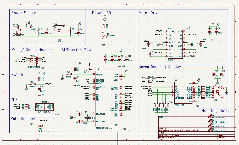
Schematic

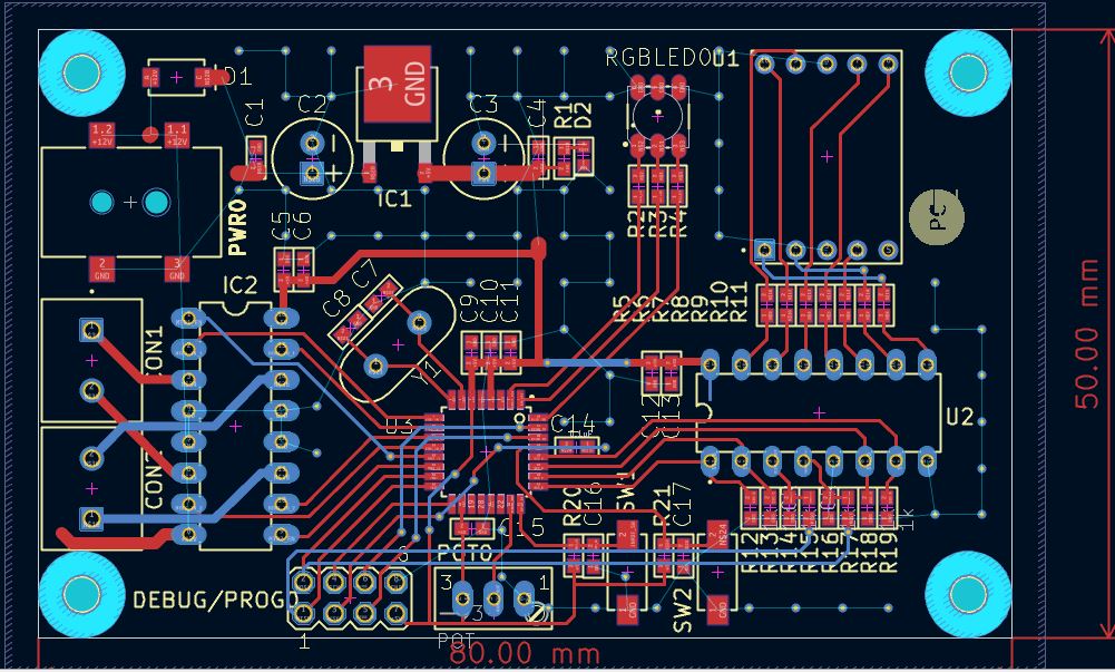
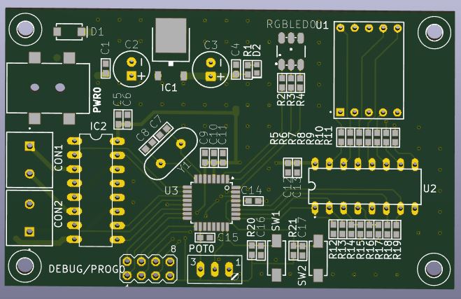
PCB Routing Layout

Layout

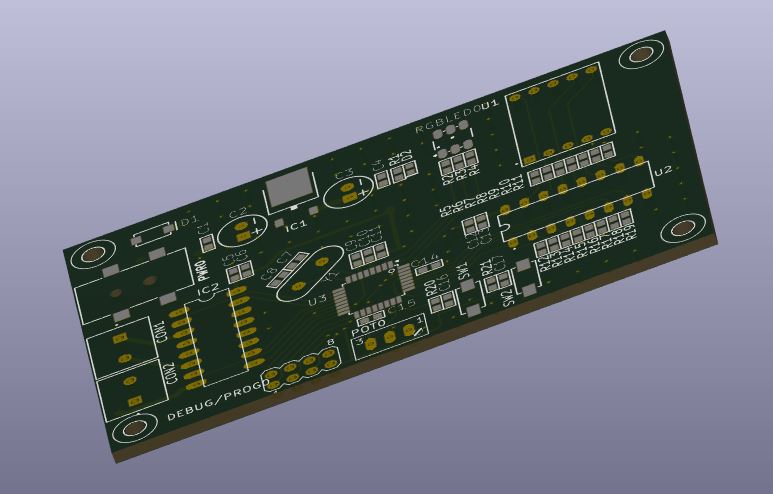
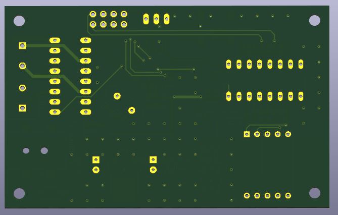
3D View

3D 3D 3D


PCB Specifications

  • Board Size: ~80mm × 50mm
  • Mounting Holes: 4 (for enclosure support)
  • Through-hole + SMD mixed design
  • Clearly labeled silkscreen for easy debugging

Components Used

ComponentDescription
ATmega328PMain microcontroller
78055V voltage regulator
L293DMotor driver IC
CD45117-segment decoder
Crystal OscillatorClock source
CapacitorsFiltering & decoupling
ResistorsCurrent limiting
RGB LEDVisual output
Push ButtonsUser input
PotentiometerAnalog input
ConnectorsPower & I/O

Tools Used

  • KiCad (Schematic + PCB Design)

Important Notes

  • This is a custom Arduino-compatible board, not an official Arduino product
  • Ensure correct power input (avoid over-voltage)
  • Verify component orientation before powering the board
  • Suitable for educational and prototyping purposes

Future Improvements

  • Add USB-to-Serial interface (CH340 / FT232)
  • Add onboard voltage regulator alternatives (switching regulator)
  • Improve grounding with full ground plane
  • Optimize routing for high-current paths
  • Add protection circuits (fuse, reverse polarity protection)

Files Included

  • .kicad_pro → Project configuration
  • .kicad_sch → Schematic design
  • .kicad_pcb → PCB layout

Learning Outcomes

This project demonstrates:

  • Embedded system hardware design
  • Multi-module PCB integration
  • Power supply design
  • Signal routing and layout optimization
  • Practical use of KiCad for real-world projects

Parts

58
QtyValueFootprintReferences
100.1uFC0603C1, C4, C6, C9, C10, C12, C14, C15, C16, C17
7330RR0603R5, R6, R7, R8, R9, R10, R11
61kR0603R12, R13, R14, R16, R18, R19
4MOUNT-HOLE2.82,8_237H1, H2, H3, H4
32kR0603R2, R3, R4
20RR0603R15, R17
2100uFCPOL-RADIAL-2.5MM-6.5MM_510C2, C3
210KR0603R20, R21
210uFC0603C5, C13
222pFC0603C7, C8
2SwitchSW_1437566-3SW1, SW2
1LED-TRICOLOR-5050_529RGBLED0
1MA04-2_162DEBUG/PROG0
116MHzHC49US_511Y1
11A/40VSMA-DIODE_514D1
122uFC0603C11
12KR0603R1
17806DTTO252_262IC1
1ATMEGA328-AUQFP80P900X900X120-32NU3
1CD4511BEDIP794W45P254L1969H508Q16U2
1DC Power JackGCT_DCJ200-05-A-XX-X_REVAPWR0
1L293DDIL16_368IC2
1LTW-C191TLALEDC1608X65ND2
1MOTOR1CONN_282836-2CON1
1MOTOR2CONN_282836-2CON2
1POTS64W_331POT0
1SSDLED_SC52-11HWAU1

Similar boards

  • 2 layers80 × 50 mmAtmega328p DevBoard Hardware, the printed circuit board in 3D

    Atmega328p DevBoard Hardware

    singharyan2001/hw-Atmega328p-DevBoard

    This Repository tracks the development of Atmega328p MCU based development board design, which is designed for learning end to end pcb designing via KiCad Software.

    58 parts
  • 2 layers79 × 107 mmEurorack spinfx, the printed circuit board in 3D

    Eurorack spinfx

    grappendorf/eurorack-spinfx

    Spin FV-1 based effects module for Eurorack systems

    80 parts16
  • 2 layers100 × 100 mmTimerClock, the printed circuit board in 3D

    TimerClock

    kseebaldt/clock_rtc

    Arduino based etc clock

    33 parts1
  • 2 layers75.5 × 46 mmHelioHeat, the printed circuit board in 3D

    HelioHeat

    E-anae/HelioHeat-PCB

    Cette section présente l'architecture d'un thermomètre autonome fonctionnant à l'aide d'un panneau solaire. L'objectif est de mesurer la température d'un lieu et d'afficher sur des afficheurs 7 segments tout en assurant…

    14 parts
  • 2 layers166.4 × 181.6 mmCalculator ver1, the printed circuit board in 3D

    Calculator ver1

    PhdWizards/4-Bit-Discrete-Transistor-Adder

    The core 4-bit binary adder is implemented entirely using discrete transistor-resistor logic. The resulting 5-bit binary value is converted to BCD using 74HC-series logic and displayed on two 7-segment displays.

    308 parts
  • 2 layers78.4 × 64.8 mmPowerNode2, the printed circuit board in 3D

    PowerNode2

    utahrobotics/Electrical-2019-2020

    67 partsMIT
  • 2 layers42.2 × 81.9 mmAtmega328p, the printed circuit board in 3D

    Atmega328p

    Sujay-1010/Rover-PCB--KiCAD

    Following pcb contains a rover pcb design, its schematics, its bom(bill of materials), and the working paramters of all the components used.

    39 parts

Questions

How big is the Customised Arduino Uno Layout PCB?

It measures 80 × 50 mm and has 2 copper layers, 1.6 mm thick.

What parts does the Customised Arduino Uno Layout use?

58 parts, built around the ATMEGA328-AU, CD4511BE, L293D and LTW-C191TLA. The full list of its parts is on this page, with links to each part's symbol and footprint where PCBKit's library has them.

Where can I download the Customised Arduino Uno Layout KiCad files?

From the sidhesh1010/Custom-Arduino-Uno-Board repository on GitHub, at the commit this page was made from: the board is Customised Arduino Uno Layout.kicad_pcb and its schematic Arduino uno Hardware Schematic.kicad_sch. PCBKit opens the board in the browser, with nothing to install.

Can I use the Customised Arduino Uno Layout design in my own project?

Its repository states no licence, so its author keeps all rights: ask sidhesh1010 before reusing the design.