Skip to the content
2 layers24 × 14.5 mmFRReceiver4, the printed circuit board in 3D

An atmel implementation of OpenSky FrSky-compatible RX

Size
24 × 14.5 mm
Copper layers
2
Thickness
1.6 mm
Parts
21
Nets
24
Pads
92
Tracks, vias
204, 31
Pours
1
Routed
Yes
KiCad
KiCad 5 (file 20171130)
Created
9 Feb 2021
Updated
2 May 2021

Overview

FRReceiver4 is an open-source printed circuit board by shaise, from the shaise/OpenSky328 repository on GitHub, published under the GPL-3.0 licence. It is a 2-layer board of 24 × 14.5 mm with 21 parts on 24 nets, routed with 204 tracks and 31 vias.

It is built around the ATMEGA328P-AU. Its parts include 5 resistors, 4 capacitors, 3 ICs, 3 connectors and 2 diodes. It belongs with the AVR (ATmega, ATtiny) boards of this library.

Main components

1

README

README.md

OpenSky328

An atmel implementation of OpenSky FrSky-compatible RX
Based on https://github.com/fishpepper/OpenSky

Description

This open project aims to develop a family of small rc receivers compatibe with FR-Sky with telemetry. List of devices:

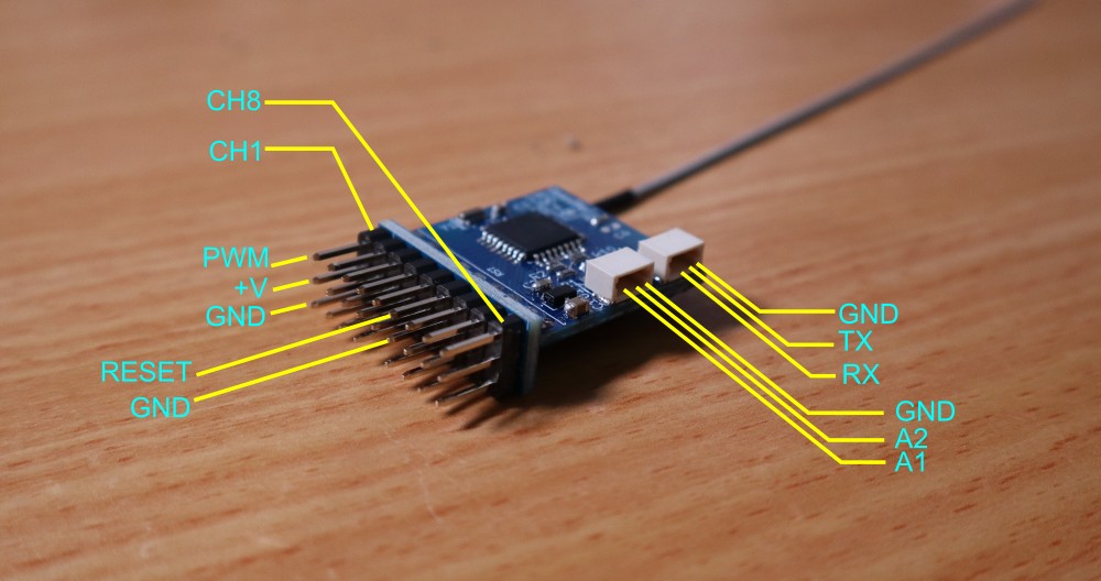
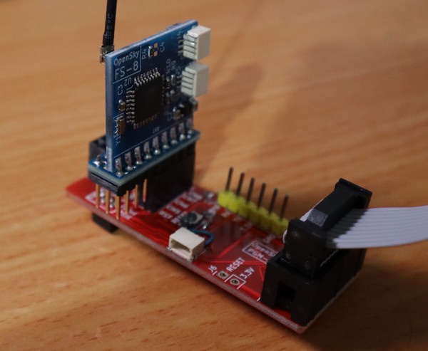
  • FR-8: An 8 channel PWM receiver with 2 analog telemetry inputs.
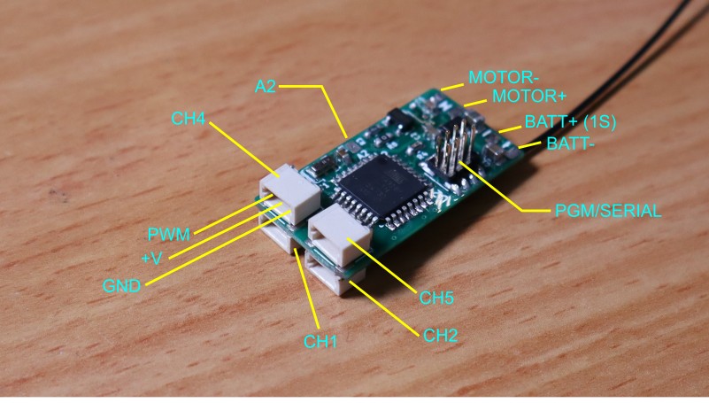
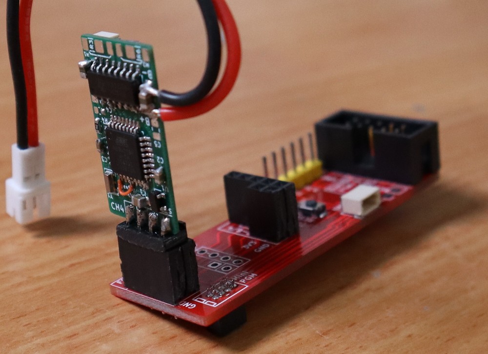
  • FR-Tiny: A 5 channel micro receiver with brushed motor ESC, for micro rc planes. Weights just 2 grams.
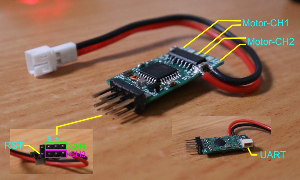
  • FR-LVH: A 1S land vehicle version with 2 bidirectional brushed motor esc (ch:1,2) and 2 servos (ch:3,4).
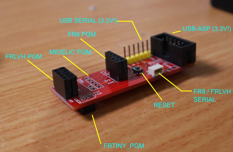
  • Programmer adapter: Lets you connect above devices to a USBASP programmer, and USB-SERIAL adapter The hardware is based on Atmega 328p microcontroller and TI CC2500 transceiver. The firmware is based on OpenSky FrSky-compatible receiver: https://github.com/fishpepper/OpenSky It is also arduino based.

1. FR-8

2. FR-Tiny

3. FR-LVH

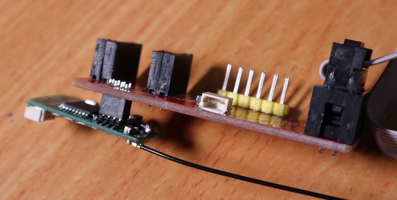
4. FR-Pgm programmer

Assembling instructions

Programming the firmware

  • Clone or download this repository.
  • Edit config.h file and set the correct PCB version by uncommenting the correct line:
CommentBoard support
#define RXBOARD_FR8_FRTINYFR-8 or FR-Tiny boards
#define RXBOARD_FRLVHFR-LVH land vehicle boards
  • You will need a USBASB compatible programmer and either the programmin adapter above (recomended) or connect your own wires.
  • NOTE!!! USBASP must be 3.3V version or you risk damaging the receiver.
  • The software is arduino compatible (Arduino nano), so it should work with the Arduino IDE, however I did not test that. Instead I recommend using the VS Studio Code IDE. You will need to install the C/C++ Addon, and the Platform IO addon (from the addon menu). Within Platform IO install the Atmel AVR platform.
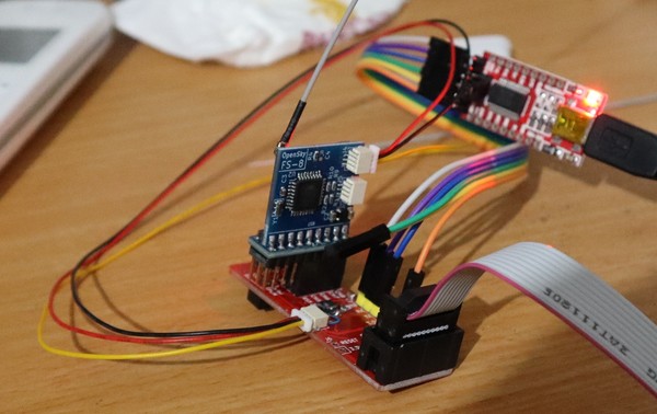
  • Connect the built receiver to the programmer using the adapter as follows:
    For FR-8:

For FR-Tiny:

For FR-LVH:

  • Now open the 'Software' folder within VS Code. If you get a mesage that a workspace was detected, go ahead and press the "open workspace" button.
  • On the left, click the PlatformIO icon (bug head), and from the "Project Tasks" menu, click the "Set fuses" line (should be under nanoatmega328->Platform). If everything is connected correctly, the Microcontroller fuses will be programmed.
  • Now just press the 'PlatformIO: Upload" button at the bottom (the right arrow) and thats it!

Usage

These receivers works with FR-Sky telemetry compatible transmitters (D8). (SW 1 and 2 off on DJT modules)

Binding

You first need to bind the receiver with the transmitter (this is a one-time operation, repeat only if you change transmitter):

  • Press and hold the bind button and then powerup the receiver. Wait for the green light to turn on.
  • Start binding procedure in your transmitter. If you are using an external module such as the DJT, Press and hold the module bind button and turn on the transmitter.
  • Wait for the red led on the receiver to start blinking. When it does, binding is complete! Turn off the transmitter and remove the receiver battery.

Setting Fail safe

turn the tranmitter on then the receiver. Wait for the receiver green light to turn on. Press and hold the Bind button on the receiver for about 5 seconds till the red led turn on. Release the button, the red led will start blinking. You now have 10 seconds to set your fail safe state using the transmitter. When the time is up, the receiver will lock this state as the failsafe mode, and restart. when the green light is on again (without the red) the process is complete. This method of setting the fail safe mode is better then the standard, since you have both hands free to move the sticks to the desired state.

Serial debugging

If you want to debug the receiver operation, you can use a serial terminal (built in VS code) to observe the debug data sent from the receiver.

  • Use a USB to serial Adapter. If you want to use the USB-serial to power the module, Make sure its a 3.3V version, or you risk damaging the modules.
  • Connect the USB-Serial adapter to the programming adapter using the marked pins.
  • Connect the programming adapter to the module as explained in the programming section.
  • For the FR-Tiny you are all set. For the FR-8 / FR-LVH you will need an extra cable (jst to jst 1.0 mm 3pin) to connect the module to the serial input:

Parts

21
QtyValueFootprintReferences
31K_0603Resistor_SMD:R_0603_1608MetricR4, R5, R7
2Conn_01x05FRMod:5PAD_ARRAYJ1, J2
1100n_0603Capacitor_SMD:C_0603_1608MetricC3
122K_0603Resistor_SMD:R_0603_1608MetricR1
122u_0603Capacitor_SMD:C_0603_1608MetricC2
14u7_0805_16VCapacitor_SMD:C_0805_2012MetricC1
15K_0603Resistor_SMD:R_0603_1608MetricR2
1ATmega328P-AUPackage_QFP:TQFP-32_7x7mm_P0.8mmU2
1Antenna_ShieldFRMod:Conn_IPEX4AE1
1CC2500_MOD6FRMod:CC2500_MOD6U3
1CSTE16MFRMod:Resonator_SMD_3.0x1.3mmY1
1GREENLED_SMD:LED_0603_1608MetricD2
1JST1.0Connector_JST:JST_SH_SM03B-SRSS-TB_1x03-1MP_P1.00mm_HorizontalJ4
1MCP1700Package_TO_SOT_SMD:SOT-23U1
1REDLED_SMD:LED_0603_1608MetricD3
1SW_BINDButton_Switch_SMD:SW_SPST_B3U-1000PSW1
1TestPointFRMod:SOLDER_PAD_1.2x1.8TP1
1dns_0603Capacitor_SMD:C_0603_1608MetricC4

More from shaise/OpenSky328

4
  • 4 layers27.5 × 14.5 mmFRReceiverLVH, the printed circuit board in 3D

    FRReceiverLVH

    shaise/OpenSky328

    An atmel implementation of OpenSky FrSky-compatible RX

    33 parts13GPL-3.0
  • 2 layers22 × 23 mmFRReceiver8, the printed circuit board in 3D

    FRReceiver8

    shaise/OpenSky328

    An atmel implementation of OpenSky FrSky-compatible RX

    25 parts13GPL-3.0
  • 2 layers60 × 20.5 mmFRReceiverProg, the printed circuit board in 3D

    FRReceiverProg

    shaise/OpenSky328

    An atmel implementation of OpenSky FrSky-compatible RX

    14 parts13GPL-3.0
  • 2 layers8 × 23.5 mmFRReceiverPins, the printed circuit board in 3D

    FRReceiverPins

    shaise/OpenSky328

    An atmel implementation of OpenSky FrSky-compatible RX

    4 parts13GPL-3.0

Similar boards

  • 2 layers50.5 × 128.5 mmOpenThereminV45, the printed circuit board in 3D

    OpenThereminV45

    GaudiLabs/OpenThereminV4

    Open Source Theremin Instrument

    107 parts249GPL-3.0
  • 2 layers152 × 88 mmRFBitBangSMT, the printed circuit board in 3D

    RFBitBangSMT

    profdc9/RFBitBanger

    A QRP digital transceiver created from readily available parts for off-the-grid maintenance

    271 parts222
  • 2 layers50.2 × 31.2 mmMCU Datalogger, the printed circuit board in 3D

    MCU Datalogger

    futureshocked/KLP4e_MCU-Datalogger

    This is the repository for the "MCU Datalogger" project.

    31 parts138MIT
  • 2 layers34 × 46 mmNfcemu, the printed circuit board in 3D

    Nfcemu

    solosky/nfc-emu

    NFC模拟器

    58 parts117Apache-2.0
  • 2 layers73 × 94 mmSportiduino base, the printed circuit board in 3D

    Sportiduino base

    sportiduino/sportiduino

    Electronic timing system for orienteering and similar outdoor sports events on Arduino

    119 parts78GPL-3.0
  • 2 layers58.9 × 44.2 mmOpenPSX2AmigaPadAdapter, the printed circuit board in 3D

    OpenPSX2AmigaPadAdapter

    SukkoPera/OpenPSX2AmigaPadAdapter

    Playstation to Commodore Amiga/CD32 Controller Adapter

    43 parts69
  • 2 layers60 × 50 mmVx8 gps prototype v2.0, the printed circuit board in 3D

    Vx8 gps prototype v2.0

    4x1md/vx8_gps

    DIY GPS module for Yaesu VX-8DR/VX-8DE handheld transceiver.

    56 parts66MIT

Questions

How big is the FRReceiver4 PCB?

It measures 24 × 14.5 mm and has 2 copper layers, 1.6 mm thick.

What parts does the FRReceiver4 use?

21 parts, built around the ATMEGA328P-AU. The full list of its parts is on this page, with links to each part's symbol and footprint where PCBKit's library has them.

Where can I download the FRReceiver4 KiCad files?

From the shaise/OpenSky328 repository on GitHub, at the commit this page was made from: the board is Hardware/FRReceiver4Pcb/FRReceiver4.kicad_pcb. PCBKit opens the board in the browser, with nothing to install.

Can I use the FRReceiver4 design in my own project?

Its repository publishes it under the GPL-3.0 licence: you may reuse it on that licence's terms (keep the author's notice, and for a copyleft licence share your changes alike).