

2 layers22 × 23 mm

 shaise/OpenSky32813
An atmel implementation of OpenSky FrSky-compatible RX
FRReceiverLVH is an open-source printed circuit board by shaise, from the shaise/OpenSky328 repository on GitHub, published under the GPL-3.0 licence. It is a 4-layer board of 27.5 × 14.5 mm with 33 parts on 31 nets, routed with 338 tracks and 58 vias.
It is built around the ATMEGA328P-AU and MX1508. Its parts include 8 capacitors, 7 resistors, 4 ICs, 3 connectors and 2 diodes. It belongs with the AVR (ATmega, ATtiny) boards of this library.
An atmel implementation of OpenSky FrSky-compatible RX
Based on https://github.com/fishpepper/OpenSky
This open project aims to develop a family of small rc receivers compatibe with FR-Sky with telemetry. List of devices:
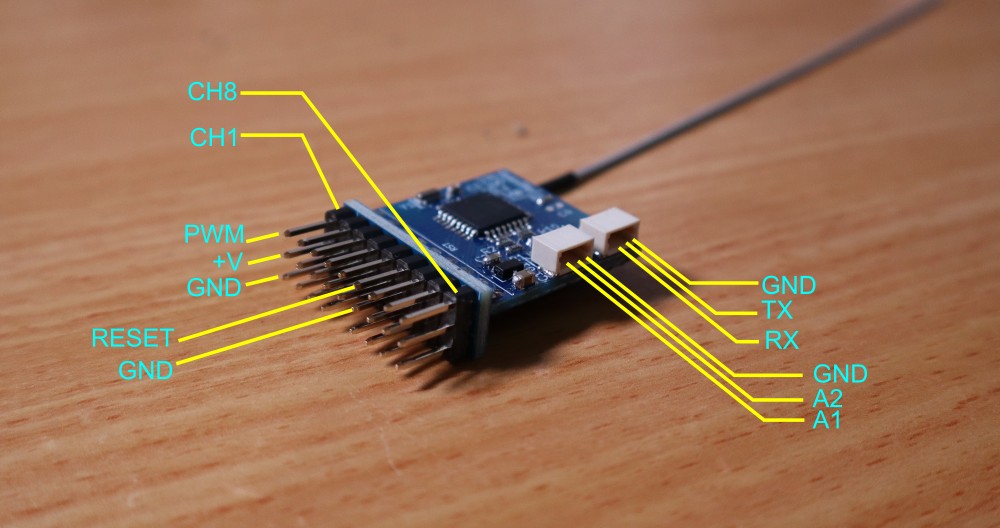
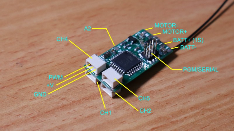
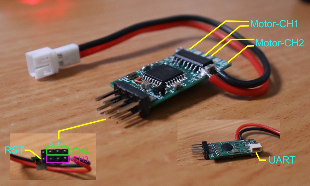
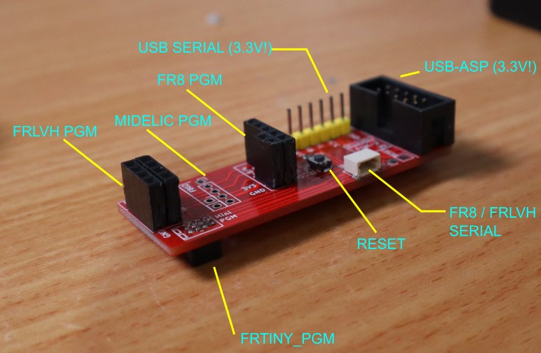
| Comment | Board support |
|---|---|
| #define RXBOARD_FR8_FRTINY | FR-8 or FR-Tiny boards |
| #define RXBOARD_FRLVH | FR-LVH land vehicle boards |
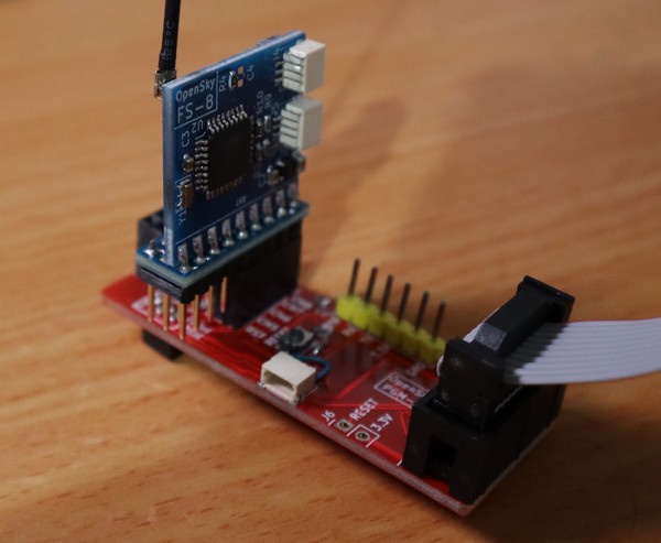
For FR-Tiny:
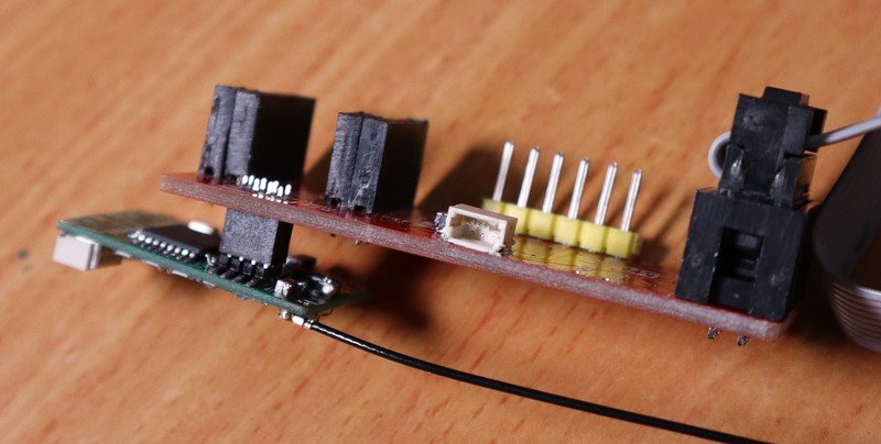
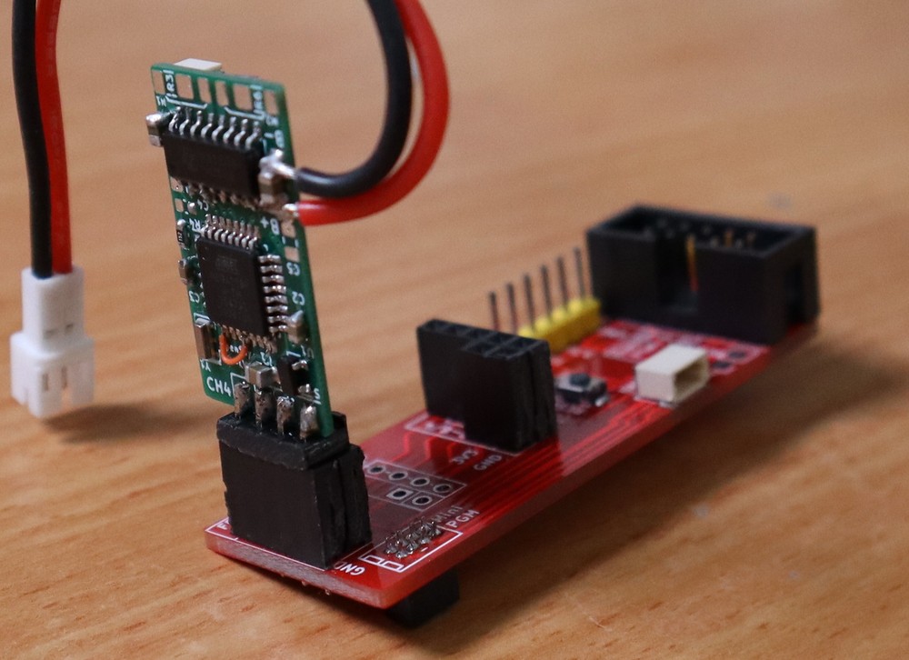
For FR-LVH:
These receivers works with FR-Sky telemetry compatible transmitters (D8). (SW 1 and 2 off on DJT modules)
You first need to bind the receiver with the transmitter (this is a one-time operation, repeat only if you change transmitter):
turn the tranmitter on then the receiver. Wait for the receiver green light to turn on. Press and hold the Bind button on the receiver for about 5 seconds till the red led turn on. Release the button, the red led will start blinking. You now have 10 seconds to set your fail safe state using the transmitter. When the time is up, the receiver will lock this state as the failsafe mode, and restart. when the green light is on again (without the red) the process is complete. This method of setting the fail safe mode is better then the standard, since you have both hands free to move the sticks to the desired state.
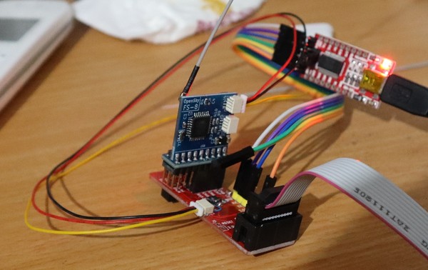
If you want to debug the receiver operation, you can use a serial terminal (built in VS code) to observe the debug data sent from the receiver.
| Qty | Value | Footprint | References |
|---|---|---|---|
| 4 | 47u_0805 | Capacitor_SMD:C_0805_2012Metric | C5, C6, C7, C8 |
| 3 | 1K_0603 | Resistor_SMD:R_0603_1608Metric | R4, R5, R7 |
| 2 | 10R_2512 | Resistor_SMD:R_1206_3216Metric | R3, R6 |
| 2 | Conn_01x04 | FRMod:4PAD_ARRAY | J1, J2 |
| 1 | 100n_0603 | Capacitor_SMD:C_0603_1608Metric | C3 |
| 1 | 22K_0603 | Resistor_SMD:R_0603_1608Metric | R1 |
| 1 | 22u_0603 | Capacitor_SMD:C_0603_1608Metric | C2 |
| 1 | 4u7_0805_16V | Capacitor_SMD:C_0805_2012Metric | C1 |
| 1 | 5K_0603 | Resistor_SMD:R_0603_1608Metric | R2 |
| 1 | ATmega328P-AU | Package_QFP:TQFP-32_7x7mm_P0.8mm | U2 |
| 1 | Antenna_Shield | FRMod:Conn_IPEX4 | AE1 |
| 1 | CC2500_MOD6 | FRMod:CC2500_MOD6 | U3 |
| 1 | CSTE16M | FRMod:Resonator_SMD_3.0x1.3mm | Y1 |
| 1 | GREEN | LED_SMD:LED_0603_1608Metric | D2 |
| 1 | JST1.0 | Connector_JST:JST_SH_SM03B-SRSS-TB_1x03-1MP_P1.00mm_Horizontal | J4 |
| 1 | MCP1700 | Package_TO_SOT_SMD:SOT-23 | U1 |
| 1 | MTR1A | FRMod:SOLDER_PAD_1.2x1.8 | TP1 |
| 1 | MTR1B | FRMod:SOLDER_PAD_1.2x1.8 | TP2 |
| 1 | MTR2A | FRMod:SOLDER_PAD_1.2x1.8 | TP3 |
| 1 | MTR2B | FRMod:SOLDER_PAD_1.2x1.8 | TP4 |
| 1 | MX1508 | Package_SO:SOIC-16_3.9x9.9mm_P1.27mm | U4 |
| 1 | RED | LED_SMD:LED_0603_1608Metric | D3 |
| 1 | SW_BIND | Button_Switch_SMD:SW_SPST_B3U-1000P | SW1 |
| 1 | V+ | FRMod:SOLDER_PAD_1.2x1.8 | TP5 |
| 1 | V- | FRMod:SOLDER_PAD_1.2x1.8 | TP6 |
| 1 | dns_0603 | Capacitor_SMD:C_0603_1608Metric | C4 |


shaise/OpenSky328
An atmel implementation of OpenSky FrSky-compatible RX

shaise/OpenSky328
An atmel implementation of OpenSky FrSky-compatible RX

zyyan20h/PCBRenewal
One other thing you can try is using the Python Scripting Console Click the button with the terminal icon at the top of the screen Type import pcbnew and press enter Type print(pcbnew.FULLBACKTRACE) and press enter The…


rayvburn/diff_drive_mapping_robot
ROS driver for the Raspberry Pi based differential drive robot

Circuit-Digest/ESP32-Cam-Surveillance-Car
Watch full video on ESP32 surveillance car


louismomo66/field-eyes_pcb
Open fieldeyesv2.kicadpro in KiCad 9. The whole circuit is one flat schematic (fieldeyesv2.kicadsch): all 168 parts are on a single page, in four framed sections.


It measures 27.5 × 14.5 mm and has 4 copper layers, 0.8 mm thick.
33 parts, built around the ATMEGA328P-AU and MX1508. The full list of its parts is on this page, with links to each part's symbol and footprint where PCBKit's library has them.
From the shaise/OpenSky328 repository on GitHub, at the commit this page was made from: the board is Hardware/FRReceiverLVH/FRReceiverLVH.kicad_pcb. PCBKit opens the board in the browser, with nothing to install.
Its repository publishes it under the GPL-3.0 licence: you may reuse it on that licence's terms (keep the author's notice, and for a copyleft licence share your changes alike).