4 layers120.5 × 269.9 mm
 seralexeev/rabbit1
rabbit source code
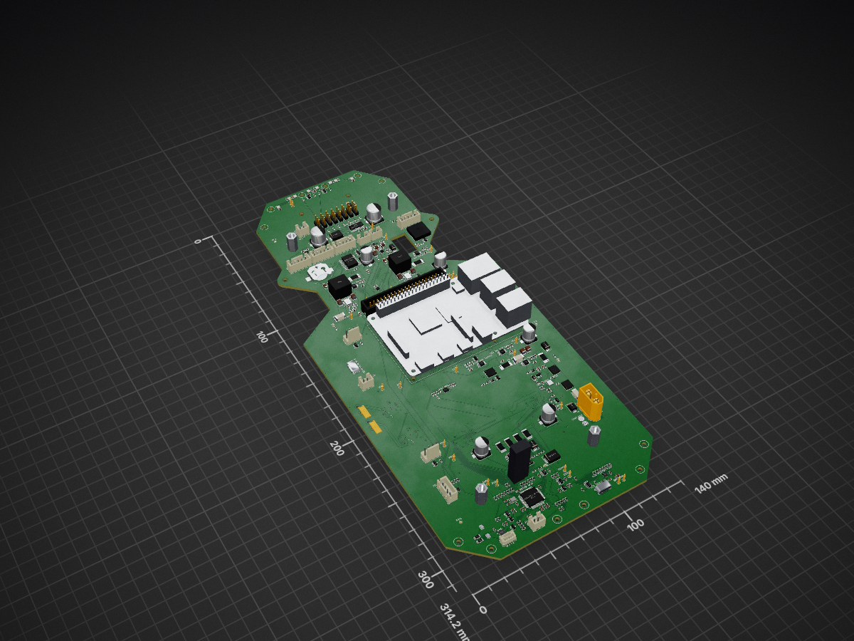
Rabbit body c is an open-source printed circuit board by seralexeev, from the seralexeev/rabbit repository on GitHub. It is an 8-layer board of 140 × 314.2 mm with 673 parts on 433 nets, routed with 4,928 tracks and 1,798 vias.
It is built around the 74AHCT1G125SE, LM61495-Q1 and PCAL6524EVJ, with the TPS259470LRPW, TPS16630PWP and 2N7002K among its other parts. Its parts include 225 resistors, 196 capacitors, 44 diodes, 25 ICs and 17 transistors.


Status 2026-10-11: netlist and two-sided placement done (floorplan of 2026-10-11 in gen/placement.json); routing on 8 layers in progress (autorouter plateau 27-29 unrouted connections, the rest is being finished by hand).
docs/reports/2026-10-10-body-pcb-rev-c.md (Russian). Its §11a decisions and the "10-11 October" section override older data.data/pcb-revc/ics/*.json (gitignored); reviews and the applied fixes are in data/pcb-revc/review/.gen/design.py is the single source of truth for parts, nets and default positions; gen/placement.json (263 overrides, applied at the end of design.py) moves parts to the 2026-10-11 floorplan.docs/log/2026-10-10-body-pcb-rev-c.md.python3 gen/footprints.py # custom footprints -> lib/rabbit_body.pretty
python3 gen/outline_revc.py # outline.json + the corner ToF poses in tof.json (from kit_outline.json)
PY=/Applications/KiCad/KiCad.app/Contents/Frameworks/Python.framework/Versions/3.9/bin/python3
$PY gen/build_board.py --no-route # placement only (without --no-route: + planes and pours, gen/routing.py)
gen/make.sh # full run: build, fill, fastroute/Freerouting, cleanup, DRC (SES=... reuses a route)
python3 gen/check_netlist.py [--board] # netlist checks (--board needs $PY)
$PY gen/drc_summary.py # kicad-cli DRC -> fab/drc.json
$PY gen/power_check.py # copper width and vias of the high-current nets after routing
python3 gen/stock.py [boards] # JLC stock of every BOM line (default 2 boards) -> fab/stock.json + csv
PLOTPY=<python with matplotlib> gen/render.sh # renders/top, bottom (seen from below), iso, *_labelledgen/outline_revc.py -> gen/outline.json): X -70..70, Y -158..156.2 (board frame: origin at the deck centre, +Y = robot front, top view). The kit plate grown on 2026-10-11 (owner): the tail goes to Y -158 and the board is ±70 wide from the tail to Y 30 (9.8 mm to the rear wheels' inner faces); the front keeps the kit's waist for the steering sweep; the nose goes to Y 156.2 so the ZED 2i (43.1 mm deep, front face on the edge) clears the front deck-3 standoffs by 2 mm. The four corner chamfers are turned square to the ToF brackets: front ±50°, rear ±135°, rear chamfers 30 mm long.ToF_Bracket_M2.5 (two M2.5 holes, flange and screw-head keep-outs), the ZED USB cable cutout 11.1 × 18 mm.gen/routing.py, gen/autoroute.py): 8 layers. Signals on F.Cu, In2.Cu, In3.Cu and B.Cu; In1 and In6 are GND planes with a GND_MOT island under the motor block (joins GND only at the star tie NT1 next to the battery connector); In4 is one VBUS plane over the whole board; In5 is a split power plane: MOT_BUS over the drive, SERVO_RAW and SERVO_PWR over the servo/arm block, +3V3_MCU under the MCU, +5V everywhere else. The router treats In1/In4/In5/In6 as power layers (vias only). The battery chain (3 mm) and the 5-10 A nets (2 mm) run on the outer layers only; 2 oz outer copper is assumed. Local pours that would trap other nets' pads are filled after routing.gen/stock.py, 2026-10-11, 2 boards): all 159 lines in JLC stock with at least 3× the need, so one JLC order with no Global Sourcing. Thinnest: Würth 2×20 C7433390 (89), PCA9685 (157), RT0603 549 Ω 0.1 % (224), STM32G474 (248), TPS259470A (331), EEHZK1E471P (404), DRV8243 (408).placement.json)| Where | Top | Bottom |
|---|---|---|
| Rear right, X 34..58, Y -112..-34 | Power entry (rev B): XT60 J1, F1 15 A, LM74800 latch, 2 mΩ battery shunt + INA238 0x40, VBUS bulk; motor-bus F2, 5 mΩ shunt shared by the LM5069 and INA238 0x41, BSC010N04LS, LM5069-1 | — |
| Rear centre, Y -120..-77 | 2 × 220 µF MOT_BUS bulk at the drivers; brake chopper (rev B); D10 TVS; D31 B540C freewheel diode | DRV8243H L/R at (-20.5 / 25.5, -83) with straps, ITRIP ladder, IPROPI and NTC; motor PH-6 J41/J42 at (∓7, -84) between the motors' rear ends with an empty ≥ 8 mm band for the OUT pours; TMP117 0x48; ToF ports J63-J65 (Y -110..-112) |
| Tail, Y -158..-120 | STM32G474 at (-13, -135) with crystal, LDO, TC2030, the E-stop NAND/ALIVE logic, IPROPI clamps; USB-C J50 + TPS2121 + USBLC6 at the rear edge right of the rear ToF bracket; CAN (TCAN1044AV, GH-4 J51, split termination) at the rear-left edge; rear bumper J14 | — |
| Left strip, X -70..-40 | E-stop XH-4, fan 2, spare 5 V XH-2, Pi power USB-C J53, fan 1 | Jetson and spare-VBAT TPS16630 (U5, U7), TVS; XT30 J21/J20 at X -65, Y -35/-48 (bottom, mating downward) |
| Y -57..-33 | IMU at (-14, -46) | — |
| Middle, Y -30..25 | Raspberry Pi 4 on 4 × M2.5 at (13, -4); no top parts under it | eFuse row under the Pi at Y -2 (fans ×2, spare 5 V, Pi USB-C) and the encoder eFuse U78 (28, 3); PCAL6524 0x22/0x23 (U37/U38) with their arrays; TCA9548A (0, 14) and TCA6416A (12, 14); ADS7128 U35 (43, 8) / U36 (43, -8) + REF3425; OVLO dividers |
| Front, Y 26..69 | Pi 2×20 header at Y 30.2 next to the Pi's own header; 5.17 V buck + INA238 0x47 and the servo buck 6.0/7.4 V + INA238 0x43; F3/F4; VBUS polymer; TMP117 0x49 between the bucks | TPS62826 3.3 V ToF rail |
| Front, Y 69..156 | Lidar XH-5 ×3, RTC + CR1220, buzzer, button, xArm block (TPS259470L U88, TLV76050, BSS138 shifter, 220 µF, PH-3 ×2), steering eFuse U83 + B540C + 2 × 470 µF, PCA9685 0x60, 8 servo headers, front bumper, MMC5983MA, ZED 2i standoffs, SK9822 ×8 along the front edge with the AHCT buffers | Lidar eFuses ×3, lidar UART resistors and ESD; ToF ports J60-J62 |
Layer rules:
check_netlist.py checks bottom heights: at most 8 mm over the motors (Y -60..-130), at most 10 mm elsewhere; nothing on the top under the Pi.data/pcb-revc/review/floorplan-2026-10-11.md): ≥ 2 mm free ring around 0.5 mm QFNs, 3 mm around the LQFP-64, no logic-GND parts over GND_MOT.Renders: renders/top_labelled.png, renders/bottom_labelled.png (seen from below, so mirrored), renders/top.png, renders/bottom.png, renders/iso.png; re-render after routing.
gen/tof.json, field of view checked in cad/robot/tof_fov.py), all on +3V3_TOF (the TPS62826 EN is the group switch); the TCA9548A is alone on the Pi's I2C6 (GPIO22/23, J3 pins 15/16, 2.2 k pull-ups); mux channels 6/7 and TCA6416A P06/P07/P16/P17 are tied off.gen/footprints.py)| Footprint | Part | Note |
|---|---|---|
TI_RXY0014A_VQFN-HR-14_3x4.5mm | DRV8243 | 4 thermal vias in the GND bar; mask polygons approximated |
TI_RPW0010A_VQFN-HR-10_2x2mm | TPS259470L/A | — |
TI_DMQ0006A_VSON-HR-6_1.5x1.5mm | TPS62826 | pads from drawing labels |
TI_RUX0012A_VQFN-HR-12_2x2.5mm | TPS2121 | pads from drawing labels |
TI_DPY0002A_X1SON-2 | TPD1E10B09 | pads 0.3 × 0.5 at ±0.35 (TI p.19) |
LED_SK9822-EC20_2x2mm | SK9822-EC20 | partly illegible drawing |
ToF_Bracket_M2.5 | ToF bracket | holes, flange keep-out under the board, screw heads on top |
rev B: TI_RPH0016B, TI_DRR0012E, NANO2 fuse, Kelvin 2512 shunt, NetTie, Pi standoffs |
PCAL6524 uses the KiCad QFN-32-1EP_5x5mm_P0.5mm_EP3.1x3.1mm, close to but not the NXP HUQFN32 land.
drv8243.json synced on 2026-10-11.EXP_RESET_N (GPIO6, 10 kΩ pull-down) resets both PCAL6524s and the TCA6416A: every switched load stays off until the Pi drives it high. The TCA9548A has its own reset (GPIO19, 10 kΩ pull-up).USB_VBUS_DET (22k/33k). TPS2121 ST goes to a test point (no MCU pin left).Tracked in docs/open-issues.md (Q49 layers, M25-M27 and M29-M30 cable and connector checks, P24-P28). In short:
rabbit-body-c.kicad_dru still names the old USB4105 for J50.design.py docstring and comments (9 INA238, 8 ToF, ADS7128 ×3, "+5V17", "56k Rp", PCAL INT on GPIO22, VBUS sense on PC3), the bottom silk "4L 1.6 mm" and the routing.py docstring ("In5 signals") (P28).| Qty | Value | Footprint | References |
|---|---|---|---|
| 68 | 100nF | Capacitor_SMD:C_0603_1608Metric | C10, C11, C12, C14A, C14B, C19, C20, C21, C120, C121, C122, C123, C181, C211, C1101, C1201 +52 |
| 59 | 10k | Resistor_SMD:R_0603_1608Metric | R17, R142, R143, R161, R163, R165, R167, R181, R183, R185, R186, R188, R1103, R1112, R1203, R1212 +43 |
| 30 | 1k | Resistor_SMD:R_0603_1608Metric | R11, R16, R24, R140, R141, R160, R192, R306, R1011, R1012, R1021, R1022, R1031, R1032, R1102, R1202 +14 |
| 28 | 1uF | Capacitor_SMD:C_0603_1608Metric | C25, C55, C322, C323, C332, C351, C352, C353, C361, C362, C363, C406, C431, C606, C782, C802 +12 |
| 22 | 100k | Resistor_SMD:R_0603_1608Metric | R14B, R18, R25, R43, R191, R401, R404, R425, R480, R481, R550, R560, R1105, R1150, R1151, R1205 +6 |
| 22 | 4.7k | Resistor_SMD:R_0603_1608Metric | R29, R30, R38, R56, R184, R887, R888, R890, R900, R901, R910, R911, R920, R921, R930, R931 +6 |
| 15 | 1nF | Capacitor_SMD:C_0603_1608Metric | C355, C356, C357, C358, C359, C365, C366, C367, C368, C784, C1105, C1205, C3510, C3511, C3512 |
| 12 | 10nF | Capacitor_SMD:C_0603_1608Metric | C24, C86, C423, C804, C814, C824, C844, C854, C864, C874, C1104, C1204 |
| 12 | 22uF | Capacitor_SMD:C_1206_3216Metric | C410, C411, C412, C413, C414, C610, C611, C612, C613, C614, C885, C886 |
| 12 | TPD4E05U06 | Package_SON:USON-10_2.5x1.0mm_P0.5mm | D41, D42, D52, D60, D61, D62, D63, D64, D65, D71, D72, D73 |
| 10 | 10 | Resistor_SMD:R_0603_1608Metric | R100, R211, R212, R221, R222, R231, R232, R261, R262, R421 |
| 9 | 10uF 50V | Capacitor_SMD:C_1210_3225Metric | C31, C32, C401, C402, C601, C602, C889, C1102, C1202 |
| 9 | 220 | Resistor_SMD:R_0603_1608Metric | R89, R3000, R3001, R3002, R3003, R3004, R3005, R3006, R3007 |
| 9 | TPS259470L | rabbit_body:TI_RPW0010A_VQFN-HR-10_2x2mm | U78, U80, U81, U82, U83, U84, U85, U86, U88 |
| 8 | 0 | Resistor_SMD:R_0603_1608Metric | R361, R423, R1104, R1106, R1111, R1204, R1206, R1211 |
| 8 | 2.2nF | Capacitor_SMD:C_0603_1608Metric | C783, C803, C813, C823, C843, C853, C863, C873 |
| 8 | 2N7002K | Package_TO_SOT_SMD:SOT-23 | Q31, Q55, Q56, Q601, Q1101, Q1102, Q1201, Q1202 |
| 8 | SK9822-EC20 | rabbit_body:LED_SK9822-EC20_2x2mm | LED1, LED2, LED3, LED4, LED5, LED6, LED7, LED8 |
| 7 | 100k x4 | Resistor_SMD:R_Array_Convex_4x0603 | RN1, RN2, RN3, RN4, RN5, RN6, RN41 |
| 7 | 10k x4 | Resistor_SMD:R_Array_Convex_4x0603 | RN7, RN8, RN9, RN10, RN11, RN12, RN40 |
| 6 | 100 | Resistor_SMD:R_0603_1608Metric | R10, R42, R55, R190, R482, R483 |
| 6 | 10uF | Capacitor_SMD:C_0805_2012Metric | C4, C9, C13, C324, C432, C489 |
| 6 | B340A | Diode_SMD:D_SMA | D88, D801, D811, D821, D841, D851 |
| 6 | LED red | LED_SMD:LED_0603_1608Metric | D2, D3, D4, D5, D6, D93 |
| 6 | fiducial | Fiducial:Fiducial_1mm_Mask2mm | FID1, FID2, FID3, FID4, FID5, FID6 |
| 5 | 220uF 35V | Capacitor_SMD:CP_Elec_8x10.5 | C30, C33, C887, C1103, C1203 |
| 5 | SMBJ20A | Diode_SMD:D_SMB | D1, D10, D13, D14, D15 |
| 4 | 1.65k | Resistor_SMD:R_0603_1608Metric | R801, R811, R821, R861 |
| 4 | 100nF | Capacitor_SMD:C_0402_1005Metric | C405, C407, C605, C607 |
| 4 | 10uF | Capacitor_SMD:C_0603_1608Metric | C311, C313, C314, C315 |
| 4 | 2.2k | Resistor_SMD:R_0603_1608Metric | R96, R97, R892, R893 |
| 4 | 22 | Resistor_SMD:R_0603_1608Metric | R130, R131, R132, R133 |
| 4 | 39R 2W | Resistor_SMD:R_2512_6332Metric | R50, R51, R52, R53 |
| 4 | 470nF | Capacitor_SMD:C_0603_1608Metric | C403, C404, C603, C604 |
| 4 | AO3400A | Package_TO_SOT_SMD:SOT-23 | Q3, Q5, Q7, Q9 |
| 4 | INA238 | Package_SO:MSOP-10_3x3mm_P0.5mm | U21, U22, U23, U26 |
| 4 | deck standoff M4 | MountingHole:MountingHole_4.3mm_M4 | H1, H2, H3, H4 |
| 3 | 1.5k | Resistor_SMD:R_0603_1608Metric | R37, R1101, R1201 |
| 3 | 150k | Resistor_SMD:R_0603_1608Metric | R40, R82, R182 |
| 3 | 22k | Resistor_SMD:R_0603_1608Metric | R44, R150, R405 |
| 3 | 22nF | Capacitor_SMD:C_0603_1608Metric | C302, C834, C884 |
| 3 | 25.5k | Resistor_SMD:R_0603_1608Metric | R312, R1109, R1209 |
| 3 | 4.7nF | Capacitor_SMD:C_0603_1608Metric | C463, C833, C883 |
| 3 | 47nF | Capacitor_SMD:C_0603_1608Metric | C23, C80, C180 |
| 3 | 5.1k | Resistor_SMD:R_0603_1608Metric | R84, R471, R472 |
| 3 | 5mR 1W | rabbit_body:R_Shunt_2512_Kelvin | R2, R3, R6 |
| 3 | 6.65k | Resistor_SMD:R_0603_1608Metric | R781, R841, R851 |
| 3 | BAT54S | Package_TO_SOT_SMD:SOT-23 | D12, D1105, D1205 |
| 3 | BSC010N04LS | Package_TO_SOT_SMD:TDSON-8-1 | Q1, Q2, Q30 |
| 2 | 10A | rabbit_body:Fuse_Littelfuse_NANO2_451_2410 | F2, F4 |
| 2 | 10pF | Capacitor_SMD:C_0603_1608Metric | C408, C608 |
| 2 | 13.7k | Resistor_SMD:R_0603_1608Metric | R1108, R1208 |
| 2 | 18pF | Capacitor_SMD:C_0603_1608Metric | C88, C89 |
| 2 | 1N4148WS | Diode_SMD:D_SOD-323 | D9, D30 |
| 2 | 1uF | Capacitor_SMD:C_0805_2012Metric | C82, C182 |
| 2 | 2.2uF | Capacitor_SMD:C_0603_1608Metric | C18, C422 |
| 2 | 20k | Resistor_SMD:R_0603_1608Metric | R320, R602 |
| 2 | 220k | Resistor_SMD:R_0603_1608Metric | R45, R46 |
| 2 | 23.2k | Resistor_SMD:R_0603_1608Metric | R164, R322 |
| 2 | 3.3uH | Inductor_SMD:L_Coilcraft_XAL1010-XXX | L4, L6 |
| 2 | 33k | Resistor_SMD:R_0603_1608Metric | R62, R151 |
| 2 | 39k | Resistor_SMD:R_0603_1608Metric | R406, R606 |
| 2 | 4.7uF | Capacitor_SMD:C_0603_1608Metric | C84, C91 |
| 2 | 4.99k | Resistor_SMD:R_0603_1608Metric | R403, R603 |
| 2 | 47.5k | Resistor_SMD:R_0603_1608Metric | R301, R303 |
| 2 | 470uF 25V | Capacitor_SMD:CP_Elec_10x10.5 | C835, C836 |
| 2 | 60.4R | Resistor_SMD:R_1206_3216Metric | R461, R462 |
| 2 | 68k | Resistor_SMD:R_0603_1608Metric | R80, R180 |
| 2 | 74AHCT1G125 | Package_TO_SOT_SMD:SOT-23-5 | U48, U49 |
| 2 | 8.25k | Resistor_SMD:R_0603_1608Metric | R1107, R1207 |
| 2 | ADS7128 | Package_DFN_QFN:WQFN-16-1EP_3x3mm_P0.5mm_EP1.68x1.68mm | U35, U36 |
| 2 | B540C | Diode_SMD:D_SMC | D31, D831 |
| 2 | DRV8243H | rabbit_body:TI_RXY0014A_VQFN-HR-14_3x4.5mm | U11, U12 |
| 2 | GND | TestPoint:TestPoint_THTPad_D1.5mm_Drill0.7mm | TP25, TP26 |
| 2 | LM61495 | rabbit_body:TI_RPH0016B_VQFN-HR-16_3.5x4.5mm | U4, U6 |
| 2 | MMBT3906 | Package_TO_SOT_SMD:SOT-23 | Q4, Q32 |
| 2 | NTC 10k | Resistor_SMD:R_0603_1608Metric | RT11, RT12 |
| 2 | PCAL6524 | Package_DFN_QFN:QFN-32-1EP_5x5mm_P0.5mm_EP3.1x3.1mm | U37, U38 |
| 2 | TPS16630 | Package_SO:HTSSOP-20-1EP_4.4x6.5mm_P0.65mm_EP3.4x6.5mm_Mask2.96x2.96mm_ThermalVias | U5, U7 |
| 2 | ZED 2i M3 standoff | MountingHole:MountingHole_3.2mm_M3 | H40, H41 |
The 541 most common of 673 parts.


misko/prompt2device
The separate vNext PCB skill and orchestrator package is available alongside the reference workflow below; existing projects keep their accepted toolchain until an explicit migration.

bruk-io/pcb-route
A fast autorouter for KiCad boards that, above all, reroutes incrementally: given the previous route, it keeps what an edit left standing and routes again only what the edit disturbed.

azonenberg/common-ibc
48-12V 72W intermediate bus converter common to all of my larger FPGA projects

AtlasAutoware/carv2
Atlas Autoware car v2: drive board (ESC, BMS, USB-C charging), Jetson carrier, printed kit

MrBlahhhh/esp32-autosport
A data logger you wire straight into a race car: 12 V and CAN come in on one 4-pin plug, sensor readings and CAN traffic get written to a microSD card.

hoeken/frothfet
Yarrboard load controller board with current sense, volt sense, fuses, and sender support.

NicholasKorth/BedCooler
A dual-zone heating and cooling controller for a bed: a 6-layer KiCad board with an STM32G474 real-time controller and a Raspberry Pi Compute Module 5 host.

riteshsalikeripatil/Battery_Management_System
PCB and schematic design files for the RBPS hardware project.
It measures 140 × 314.2 mm and has 8 copper layers, 2 mm thick.
673 parts, built around the 74AHCT1G125SE, LM61495-Q1, PCAL6524EVJ and TPS259470LRPW. The full list of its parts is on this page, with links to each part's symbol and footprint where PCBKit's library has them.
From the seralexeev/rabbit repository on GitHub, at the commit this page was made from: the board is pcb/rabbit-body-c/rabbit-body-c.kicad_pcb and its schematic pcb/rabbit-board/rabbit-board.kicad_sch. PCBKit opens the board in the browser, with nothing to install.
Its repository states no licence, so its author keeps all rights: ask seralexeev before reusing the design.