


2 layers36.5 × 49.5 mm
V485 controller
gabrielyoung92/gabs_microSMT_PickAndPlace
Independent reorganisation of MicroSMT feeder and PNPv3 files, previews and documentation, with upstream attribution and ChatGPT assistance.
33 parts1

 NicholasKorth/BedCooler11
A dual-zone heating and cooling controller for a bed: a 6-layer KiCad board with an STM32G474 real-time controller and a Raspberry Pi Compute Module 5 host.
BedCooler is an open-source printed circuit board by NicholasKorth, from the NicholasKorth/BedCooler repository on GitHub. It is a 6-layer board of 131.5 × 132.4 mm with 258 parts on 312 nets, routed with 1,751 tracks and 966 vias.
It is built around the STM32G474RET6, DRV8701ERGER and TPS54331DR-JSM, with the GL823K-HCY04, 2920L500/30GR and RT9742SNGV among its other parts. Its parts include 105 capacitors, 68 resistors, 22 connectors, 14 transistors and 12 ICs. It belongs with the STM32 and Raspberry Pi (Linux) boards of this library.


A dual-zone heating and cooling controller for a bed: a 6-layer KiCad board with an STM32G474 real-time controller and a Raspberry Pi Compute Module 5 host.
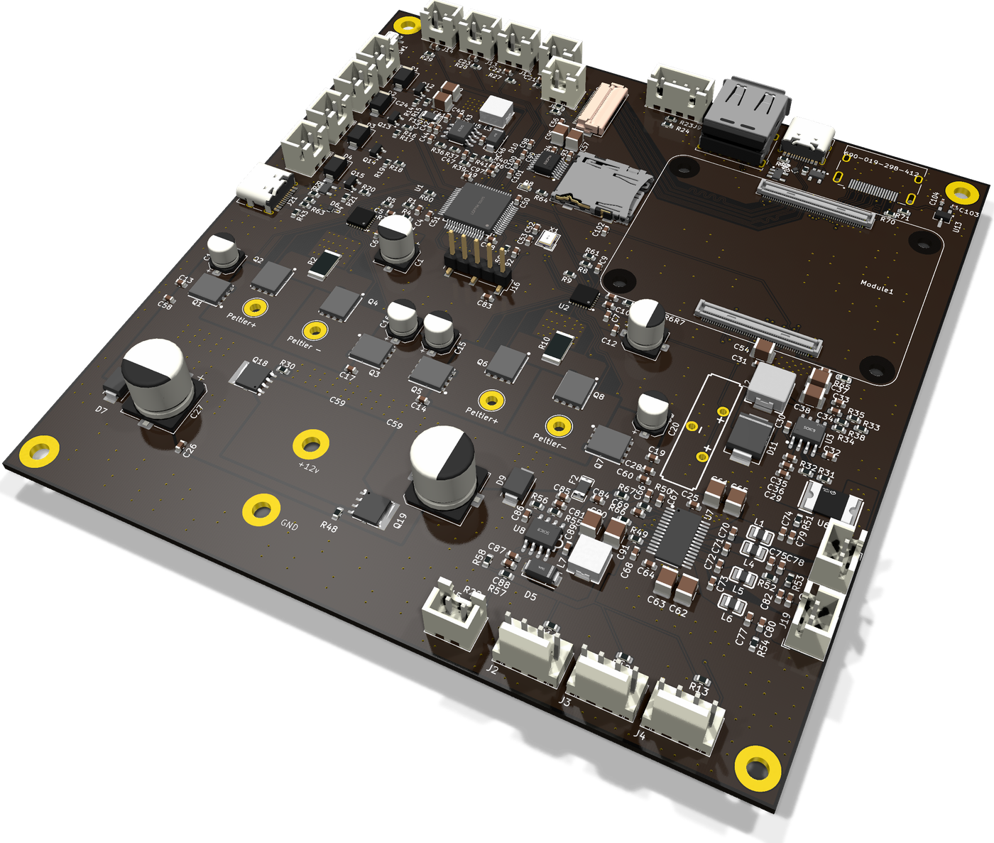
3D render from the board file. The Compute Module 5 itself has no 3D model; its two connectors sit along the right edge.
BedCooler regulates body temperature during sleep. Each side of the bed has its own pair of Peltier (thermoelectric) modules that can heat or cool, so two people can each choose their own temperature. Pumps, valves and fans move the heat; thermistors, a reservoir float switch and a water sensor report back. A touchscreen sets targets and schedules, and the microcontroller keeps each side on target.
I built it and use it every night. It pairs with my Slim Sleep Tracker wearable.
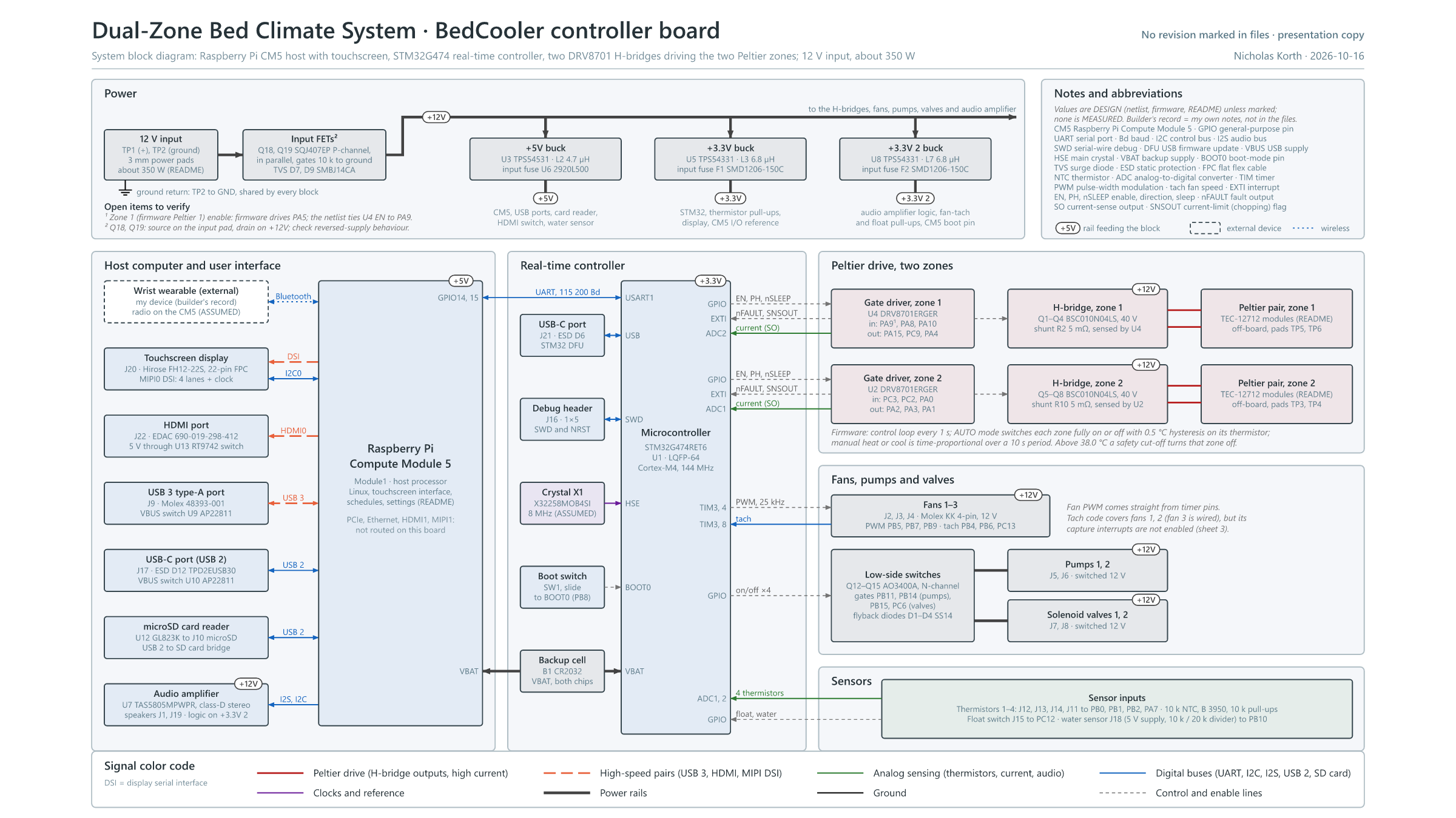
Block diagram as SVG. The full presentation package (overview, block diagram, firmware architecture, board renders and schematic pages) is in docs/bedcooler_package.pdf.
Values come from the design files (schematic, board and firmware), not from measurements.
| Processors | STM32G474RET6 real-time controller (Cortex-M4, 144 MHz); Raspberry Pi Compute Module 5 host |
| Peltier drive | 2 DRV8701 gate drivers, 8 BSC010N04LS 40 V MOSFETs (one full bridge per side), 5 mΩ current shunts; two pairs of TEC-12712 modules |
| Loads | 2 pumps and 2 valves on AO3400A low-side switches; 3 fans, 25 kHz PWM with tach |
| Sensing | 4 NTC thermistors (10 k, B 3950), float switch, water sensor, bridge current |
| Power | 12 V input, about 350 W; +5V, +3.3V and a second +3.3V rail from three buck converters |
| Interfaces | Touchscreen (MIPI DSI), HDMI, USB 3 type-A, two USB-C (USB 2), microSD, stereo class-D amplifier |
| Board | 131.5 x 132.4 mm, 6 copper layers, 1.6 mm; 258 parts, all on the top side |
| Firmware | Bare-metal C on the STM32 HAL; plain-text commands over UART |
hardware/    KiCad 9 project (schematic, routed board), footprint and symbol libraries,
             3D models (packages3d/), production files (Gerbers, IPC netlist, BOM and placement)
firmware/    bedcoolerstm2: STM32CubeIDE project for the STM32G474
docs/ presentation package PDF, diagrams and renders, an older schematic printOpen hardware/BedCooler.kicad_pro in KiCad 9. Schematic sheets:
| File | Contents |
|---|---|
BedCooler.kicad_sch | Root: STM32G474, Compute Module 5, display, HDMI, debug header, backup cell |
powerreg.kicad_sch | 12 V input FETs and the three buck converters |
untitled.kicad_sch | The two DRV8701 H-bridges (sheet "H bridge") |
Fan_control.kicad_sch | Fan, pump and solenoid valve drivers |
Sensors.kicad_sch | Thermistor, float switch and water sensor inputs |
CM5 Ports.kicad_sch | USB 3, USB-C, microSD card reader and USB power switches |
Audio.kicad_sch | TAS5805M class-D amplifier |
The board was laid out for the JLCPCB 6-layer stackup JLC06162H-3313, with impedance-controlled traces for the high-speed pairs. The Gerbers are in hardware/production/test_bedcooler.zip, and the fabrication-toolkit archive in hardware/production/backups/ also holds the BOM and placement files. The Gerbers are dated 2025-08-13, before the last board edits, so regenerate them from the board file before ordering.
More views: one-page overview, top render, signal map, functional layout.
The 3D model for the Compute Module 5 is not included; the board references packages3d/471511051.stp, which can be added from the Raspberry Pi CM5 IO board KiCad files.
firmware/bedcoolerstm2 is an STM32CubeIDE project (HAL, CubeMX .ioc included).
safety on|off).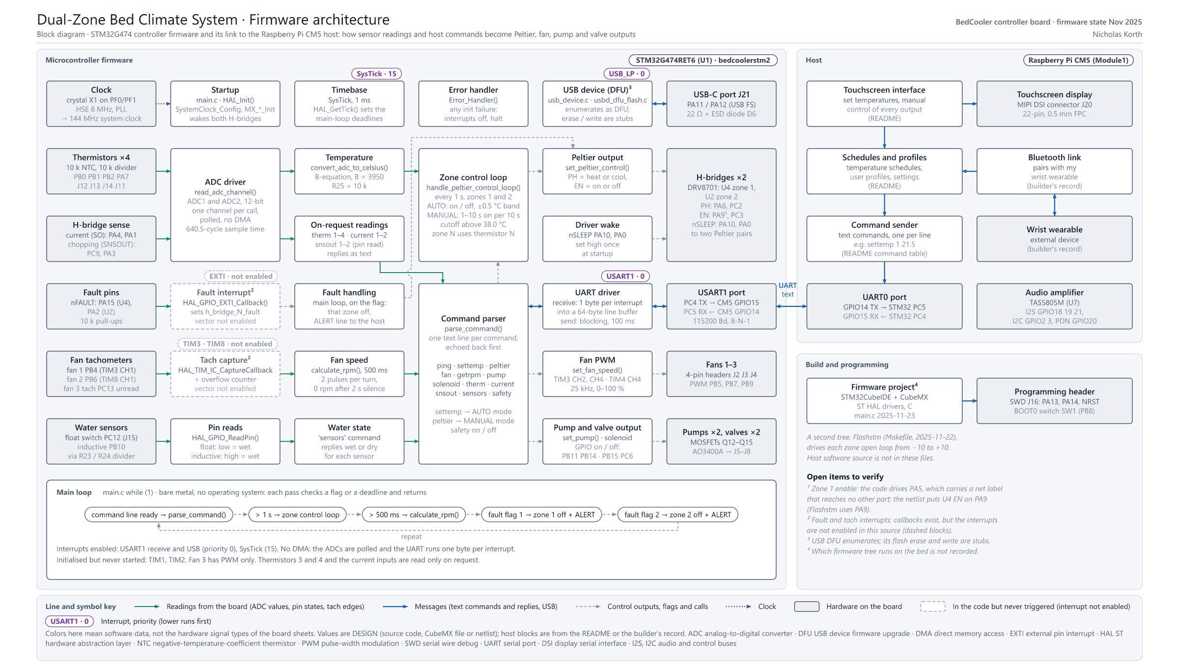
| Command | Example | Effect |
|---|---|---|
ping | ping | Replies pong |
settemp | settemp 1 21.5 | Target temperature for zone 1 or 2 in °C; enables AUTO mode |
peltier | peltier 1 cool 5 | Manual heat, cool or off; optional duty 1-10 (seconds on per 10 s) |
pump | pump 2 on | Pump 1 or 2 on or off |
solenoid | solenoid 1 on | Valve 1 or 2 on or off |
fan | fan 3 75 | Fan 1-3 speed in percent |
getrpm | getrpm 2 | Fan RPM |
therm | therm 4 | Raw ADC value and temperature for thermistor 1-4 |
current | current 1 | Raw current-sense reading for zone 1 or 2 |
snsout | snsout 2 | Whether current chopping is active for a zone |
sensors | sensors | Float switch and water sensor state |
safety | safety off | Enables or disables the 38 °C cutoff |
File > Import > General > Existing Projects into Workspace, and select firmware/bedcoolerstm2.Project > Build All. The Debug build uses about 82 KB of flash.Run As > STM32 C/C++ Application.This runs at 12 V and about 350 W, with water circulating near the electronics. Fuse the supply, keep the board away from the water loop, and test the leak and float sensors before leaving it running unattended.
CC BY-NC-SA 4.0: Creative Commons Attribution-NonCommercial-ShareAlike 4.0 International. You may share and adapt this work for non-commercial purposes with attribution, under the same license. The ST HAL drivers and USB middleware in firmware/ keep their own ST licenses.
| Qty | Value | Footprint | References |
|---|---|---|---|
| 30 | .1uF | Capacitor_SMD:C_0603_1608Metric | C2, C3, C10, C12, C13, C14, C17, C19, C25, C28, C30, C31, C33, C43, C101, C102 +14 |
| 14 | 1uF | Capacitor_SMD:C_0603_1608Metric | C4, C5, C6, C7, C8, C9, C26, C56, C60, C68, C69, C99, C100, C105 |
| 10 | Conn_01x02_Pin | Connector_JST:JST_XH_B2B-XH-A_1x02_P2.50mm_Vertical | J5, J6, J7, J8, J11, J12, J13, J14, J15, J23 |
| 9 | 2200pF | Capacitor_SMD:C_0603_1608Metric | C34, C74, C75, C76, C77, C78, C79, C80, C82 |
| 8 | 10KOhm | Resistor_SMD:R_0603_1608Metric | R11, R12, R22, R23, R26, R27, R28, R29 |
| 8 | BSC010N04LS | easyeda2kicad:PG-TDSON-8-FL_L5.0-W6.0-P1.27-LS6.2-BL | Q1, Q2, Q3, Q4, Q5, Q6, Q7, Q8 |
| 7 | 10kOhm | Resistor_SMD:R_0603_1608Metric | R1, R8, R13, R30, R48, R60, R61 |
| 7 | 4.7k | Resistor_SMD:R_0603_1608Metric | R50, R66, R67, R68, R69, R70, R71 |
| 7 | 4.7uF | Capacitor_SMD:C_0603_1608Metric | C35, C36, C40, C41, C67, C81, C84 |
| 6 | .01uF | Capacitor_SMD:C_0603_1608Metric | C29, C32, C42, C44, C85, C86 |
| 6 | 47uF | Capacitor_SMD:C_1210_3225Metric | C37, C38, C39, C45, C90, C91 |
| 4 | .22uF | Capacitor_SMD:C_0603_1608Metric | C70, C71, C72, C73 |
| 4 | 100 Ohms | Resistor_SMD:R_0603_1608Metric | R15, R16, R18, R20 |
| 4 | 100 uF | Capacitor_SMD:CP_Elec_5x5.4 | C15, C16, C18, C20 |
| 4 | 10Kohm | Resistor_SMD:R_0603_1608Metric | R14, R17, R19, R21 |
| 4 | 22uF | Capacitor_SMD:C_1210_3225Metric | C61, C62, C63, C65 |
| 4 | 5.1k | Resistor_SMD:R_0603_1608Metric | R42, R43, R46, R47 |
| 4 | 67 ohm | Resistor_SMD:R_0603_1608Metric | R51, R52, R53, R54 |
| 4 | AO3400A | Package_TO_SOT_SMD:SOT-23 | Q12, Q13, Q14, Q15 |
| 4 | C | Capacitor_SMD:C_0603_1608Metric | C21, C22, C23, C24 |
| 4 | NFZ2MSM301SN10L | easyeda2kicad:L0806 | L1, L4, L5, L6 |
| 4 | SS14 | Diode_SMD:D_SMA | D1, D2, D3, D4 |
| 3 | 10.2k | Resistor_SMD:R_0603_1608Metric | R33, R40, R57 |
| 3 | 10k | Resistor_SMD:R_0603_1608Metric | R49, R59, R65 |
| 3 | AP22811AW5-7 | easyeda2kicad:SOT-25-5_L3.0-W1.6-P0.95-LS2.8-BL | U9, U10, U11 |
| 3 | Conn_01x04_Pin | Connector_Molex:Molex_KK-254_AE-6410-04A_1x04_P2.54mm_Vertical | J2, J3, J4 |
| 3 | TestPoint | TestPoint:TestPoint_THTPad_D4.0mm_Drill2.0mm | Peltier -, Peltier-, Peltier+ |
| 2 | 1000Uf | Capacitor_SMD:CP_Elec_10x10.5 | C27, C59 |
| 2 | 1000pF | Capacitor_SMD:C_0603_1608Metric | C47, C88 |
| 2 | 100n | Capacitor_SMD:C_0402_1005Metric | C103, C104 |
| 2 | 10UF | Capacitor_SMD:C_1210_3225Metric | C57, C95 |
| 2 | 15pF | Capacitor_SMD:C_0603_1608Metric | C52, C53 |
| 2 | 1kOhm | Resistor_SMD:R_0603_1608Metric | R3, R7 |
| 2 | 22 | Resistor_SMD:R_0603_1608Metric | R62, R63 |
| 2 | 220uF | Capacitor_SMD:CP_Elec_6.3x7.7 | C1, C11 |
| 2 | 3.24k | Resistor_SMD:R_0603_1608Metric | R41, R58 |
| 2 | 30kOhm | Resistor_SMD:R_0603_1608Metric | R4, R6 |
| 2 | 332k | Resistor_SMD:R_0603_1608Metric | R36, R55 |
| 2 | 33kOhm | Resistor_SMD:R_0603_1608Metric | R5, R9 |
| 2 | 47pF | Capacitor_SMD:C_0603_1608Metric | C46, C87 |
| 2 | 5 mOhm | Resistor_SMD:R_2512_6332Metric | R2, R10 |
| 2 | 68.1k | Resistor_SMD:R_0603_1608Metric | R37, R56 |
| 2 | B340A-13-F | easyeda2kicad:SMA_L4.4-W2.6-LS5.0-RD | D5, D10 |
| 2 | Conn_01x02_Socket | Connector_JST:JST_XH_B2B-XH-A_1x02_P2.50mm_Vertical | J1, J19 |
| 2 | DRV8701ERGER | easyeda2kicad:VQFN-24_L4.0-W4.0-P0.50-BL-EP2.5 | U2, U4 |
| 2 | FXL0530-6R8-M | easyeda2kicad:IND-SMD_L5.4-W5.2_FXL0530 | L3, L7 |
| 2 | SMBJ14CA_C151253 | easyeda2kicad:SMB_L4.6-W3.6-LS5.3-BI | D7, D9 |
| 2 | SMD1206-150C-16V | easyeda2kicad:F1206 | F1, F2 |
| 2 | SQJ407EP-T1_GE3 | easyeda2kicad:POWERPAK-SO-8_L6.2-W5.1-P1.27-BL | Q18, Q19 |
| 2 | TPD2EUSB30ADRTR | easyeda2kicad:SOT-9X3-3_L1.0-W0.8-P0.35-LS1.0-BR | D6, D12 |
| 2 | TPS54331DR | easyeda2kicad:SOIC-8_L5.0-W4.0-P1.27-LS6.0-BL | U5, U8 |
| 2 | TestPoint | Library:Power_pad_3mm_drill | +12v, GND |
| 2 | USB_C_Receptacle_USB2.0_16P | Connector_USB:USB_C_Receptacle_HRO_TYPE-C-31-M-12 | J17, J21 |
| 1 | .1uf | Capacitor_SMD:C_0603_1608Metric | C93 |
| 1 | 1.96k | Resistor_SMD:R_0603_1608Metric | R34 |
| 1 | 100uF | Capacitor_SMD:C_1210_3225Metric | C54 |
| 1 | 130k | Resistor_SMD:R_0603_1608Metric | R31 |
| 1 | 1k | Resistor_SMD:R_0603_1608Metric | R64 |
| 1 | 1uf | Capacitor_SMD:C_0603_1608Metric | C97 |
| 1 | 20k | Resistor_SMD:R_0603_1608Metric | R24 |
| 1 | 29.4k | Resistor_SMD:R_0603_1608Metric | R39 |
| 1 | 2920L500/30GR | easyeda2kicad:F2920 | U6 |
| 1 | 37.4k | Resistor_SMD:R_0603_1608Metric | R35 |
| 1 | 51.1 | Resistor_SMD:R_0603_1608Metric | R38 |
| 1 | 665k | Resistor_SMD:R_0603_1608Metric | R32 |
| 1 | 690-019-298-412 | CM5IO:EDAC 690-019-298-412 | J22 |
| 1 | CDBC540-HF | easyeda2kicad:SMC_L6.9-W5.9-LS7.9-RD | D11 |
| 1 | CR2032-BS-5-1 | easyeda2kicad:BAT-TH_CR2032-BS-5-1 | B1 |
| 1 | ComputeModule5-CM5 | CM5IO:Raspberry-Pi-5-Compute-Module | Module1 |
| 1 | Conn_01x04_Pin | Connector_JST:JST_XH_B4B-XH-A_1x04_P2.50mm_Vertical | J18 |
| 1 | Conn_01x05 | Connector_PinHeader_2.54mm:PinHeader_1x05_P2.54mm_Vertical_SMD_Pin1Right | J16 |
| 1 | Conn_01x22_Female | CM5IO:Hirose_FH12-22S-0.5SH_1x22-1MP_P0.50mm_Horizontal | J20 |
| 1 | FXL0630-4R7-M | easyeda2kicad:IND-SMD_L7.0-W6.6 | L2 |
| 1 | GL823K-HCY04 | easyeda2kicad:SSOP-16_L4.9-W3.9-P0.64-LS6.0-BL | U12 |
| 1 | LED | LED_SMD:LED_0603_1608Metric | D8 |
| 1 | Micro_SD_Card | Connector_Card:microSD_HC_Wuerth_693072010801 | J10 |
| 1 | RT9742SNGV | Package_TO_SOT_SMD:TSOT-23_HandSoldering | U13 |
| 1 | STM32G474RET6 | easyeda2kicad:LQFP-64_L10.0-W10.0-P0.50-LS12.0-BL | U1 |
| 1 | SW_SPDT | Button_Switch_SMD:SW_SPDT_PCM12 | SW1 |
| 1 | TAS5805MPWPR | easyeda2kicad:HTSSOP-28_L9.7-W4.4-P0.65-LS6.4-BL-EP | U7 |
The 250 most common of 258 parts.
gabrielyoung92/gabs_microSMT_PickAndPlace
Independent reorganisation of MicroSMT feeder and PNPv3 files, previews and documentation, with upstream attribution and ChatGPT assistance.

bradport02/RX8-Infotainment_System
An infotainment system for the Mazda RX-8 that integrates seamlessly with the climate control unit.


PaulBichl/VibePCB-bench-psu
USB-C PD (20 V) powered bench supply, 2 independent channels, 1.6-16.6 V / 3 A each, constant voltage / constant current, designed with VibePCB.

LEDs-by-glowingkitty/GlowBand
GlowBand is an exciting LED wristband. For dancing at parties and festivals, for long-time exposure photography, and for everyday situations that need some light.

LEDs-by-glowingkitty/GlowSign
A battery powered LED sign for your laptop, or where ever else you want to use it!

byrantech/laptop
anyon_e, a highly integrated, high end, open source laptop. Attempt the impossible.

It measures 131.5 × 132.4 mm and has 6 copper layers, 1.6 mm thick.
258 parts, built around the STM32G474RET6, DRV8701ERGER, TPS54331DR-JSM and GL823K-HCY04. The full list of its parts is on this page, with links to each part's symbol and footprint where PCBKit's library has them.
From the NicholasKorth/BedCooler repository on GitHub, at the commit this page was made from: the board is hardware/BedCooler.kicad_pcb and its schematic hardware/Audio.kicad_sch. PCBKit opens the board in the browser, with nothing to install.
Its repository states no licence, so its author keeps all rights: ask NicholasKorth before reusing the design.